Table of Contents
Advertisement
Copyright
Copyright © 2013 MiTAC International Corporation. All rights reserved. No part of
this manual may be reproduced or translated without prior written consent from
MiTAC International Corporation.
Trademark
All registered and unregistered trademarks and company names contained in this
manual are property of their respective owners including, but not limited to the
following.
®
TYAN
is a trademark of MiTAC International Corporation.
®
Intel
is a trademark of Intel
AMI, AMI BIOS are trademarks of AMI Technologies.
®
Microsoft
, Windows
®
Nuvoton
is a trademark of Nuvoton Technology Corporation.
Notice
Information contained in this document is furnished by MiTAC International
Corporation and has been reviewed for accuracy and reliability prior to printing.
MiTAC assumes no liability whatsoever, and disclaims any express or implied
warranty, relating to sale and/or use of TYAN
warranties relating to fitness for a particular purpose or merchantability. MiTAC
retains the right to make changes to product descriptions and/or specifications at
any time, without notice. In no event will MiTAC be held liable for any direct or
indirect, incidental or consequential damage, loss of use, loss of data or other
malady resulting from errors or inaccuracies of information contained in this
document.
S5535/S5535-HE
Version 1.0a
®
Corporation.
®
are trademarks of Microsoft Corporation.
http://www.tyan.com
®
products including liability or
1
Advertisement
Table of Contents

Related Manuals for TYAN S5535


Summary of Contents for TYAN S5535
- Page 1 Corporation and has been reviewed for accuracy and reliability prior to printing. MiTAC assumes no liability whatsoever, and disclaims any express or implied ® warranty, relating to sale and/or use of TYAN products including liability or warranties relating to fitness for a particular purpose or merchantability. MiTAC retains the right to make changes to product descriptions and/or specifications at any time, without notice.
- Page 2 http://www.tyan.com...
-
Page 3: Table Of Contents
3.5 Boot ....................74 3.6 Security.................... 78 3.7 Save & Exit ..................79 Chapter 4: Diagnostics................81 4.1 Flash Utility ..................81 4.2 AMIBIOS Post Code (Aptio) ............82 Appendix: Fan and Temp Sensors............89 Glossary..................... 93 Technical Support ..................99 http://www.tyan.com... -
Page 4: Before You Begin
The retail motherboard package should contain the following: 1 x S5535 Motherboard 5 x SATA Cable 1 x USB 3.0 Bracket 1 x Rear IO Shield 1 x S5535 Quick reference guide ® 1 x TYAN Driver’s and Utilities DVD IMPORTANT NOTE: Sales sample may not come with the accessory listed above. -
Page 5: Chapter 1: Instruction
, the S5535 is capable of offering scalable 32 and 64-bit computing, high-bandwidth memory design, and lightning-fast PCI-E bus implementation. The S5535 not only empowers you in today’s demanding IT environment but also offers a smooth path for future application upgradeability. All of these rich feature sets provides the S5535 with the power and flexibility to meet demanding requirements for today’s IT environments. - Page 6 (1) Quick Installation Guide Package Installation CD (1) TYAN installation CD Contains SATA (5) SATA signal cables Cable (1) CCBL-035J, 2-port USB bracket cable TYAN S5535 (S5535AG2NR-HE) (BTO) Intel Xeon E3-1200 v3, i3 (22nm/Haswell) series Supported CPU Series Processor processors http://www.tyan.com...
- Page 7 2.7/PnP/Wake on LAN / ACPI 3.0/ACPI sleeping states S3,S4,S5 / PXE boot support Form Factor Micro ATX Physical Dimension Board Dimension 9.6"x9.6" (243.8x243.8mm) Operating OS supported list Please refer to our Intel OS supported list. System FCC (DoC) Class A Regulation http://www.tyan.com...
-
Page 8: Software Specifications
(1) Quick Installation Guide Package Installation CD (1) TYAN installation CD Contains SATA (5) SATA signal cables Cable (1) CCBL-035J, 2-port USB bracket cable 1.3 Software Specifications ® For OS (operation system) support, please check with TYAN support for latest information. http://www.tyan.com... -
Page 9: Chapter 2: Board Installation
(5) Inspect the board for damage. The following pages include details on how to install your motherboard into your chassis, as well as installing the processor, memory, disk drives and cables. NOTE: Do not apply power to the board if it has been damaged. http://www.tyan.com... -
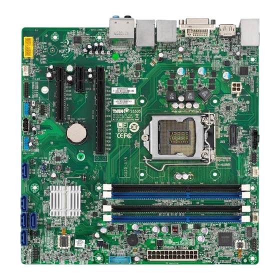
Page 10: Board Image
2.1 Board Image S5535 This picture is representative of the latest board revision available at the time of publishing. The board you receive may not look exactly like the above picture. http://www.tyan.com... -
Page 11: Block Diagram
2.2 Block Diagram S5535 Block Diagram http://www.tyan.com... -
Page 12: Mainboard Mechanical Drawing
2.3 Mainboard Mechanical Drawing http://www.tyan.com... -
Page 13: Board Parts, Jumpers And Connectors
The board you receive may not look exactly like the above diagram. But for the DIMM number please refer to the above placement for memory installation. For the latest board revision, please visit our web site at http://www.tyan.com. http://www.tyan.com... - Page 14 7 Front Audio Header (FP_AUDIO_1) 22 USB3.0 Header (J24) 8 Rear FAN (J17) 23 Speaker Header (J83) 24 24-pin Power Connector 9 TYAN Module Header (DBG_HD1) (ATX24P_1) 10 Front USB2.0 Header 25 COM Port Header (J77) (FP_USB_3) 11 USB Type-A Connector (J27) 26 Front FAN (J20) 12 Front USB2.0 Header...
- Page 15 FP AUDIO 1 http://www.tyan.com...
- Page 16 Signal Signal HD LED+ PLED+ HD LED- PLED- RST SW- PWR SW+ RST SW+ PWR SW- J83: Speaker Header Signal 5VSB FLOATING SPKR_BUZZ_IN SPKR_BUZZ FP_AUDIO_1: Front Audio Header Signal Signal FP_MIC_L AGND FP_MIC_R AUDIO_Detect AUO_HPOUT_R AUO_SENSE_MIC FIO_SENSE AUO_HPOUT_L AUO_SENSE_HP http://www.tyan.com...
- Page 17 SATA _6G_1 FP USB 2 INTRD1 FP USB 3 SATA SATA SATA SATA _6G_5 _6G_3 _6G_2 _6G_0 http://www.tyan.com...
- Page 18 Serial ATA cable. SATA TX DN NOTE: SATA_6G_5 SATA RX DN supports SATA DOM SATA RX DP Device. J24: USB3.0 Header Signal Signal VCCUSB3_FRONT VCCUSB3_FRONT USB30RX_ON_R USB30TX_1N_R USB30RX_OP_R USB30RX_1P_R USB30TX_ON_R USB30TX_1N_R USB30TX_OP_R USB30TX_1P_R USB_PCH DN0_R USB_PCH_DN1_R USB_PCH DP0_R USB_PCH_DP1_R USB_PCH_ OC01_N http://www.tyan.com...
- Page 19 DBG HD1 http://www.tyan.com...
- Page 20 DBG_HD1: TYAN Module Header Signal Signal VCC3 LPC_LFRAME_N LAD0 LAD1 LPC_RST_N LAD2 LAD3 33M_CLK SERIRQ PRESENT_N 3V3_VSB GPIO1 GPIO2 J27: Vertical Type-A USB Connector Signal Signal USB_DN USB_DP J31: PSMI Connector Signal PSMI_SCL PSMI_SDA RSVD J4: Clear CMOS Jumper You can reset the CMOS settings by using this jumper. This can be useful if you have forgotten your system/setup password, or need to clear the system BIOS setting.
- Page 21 http://www.tyan.com...
- Page 22 J2: ME Jumper Pin 1-2 Closed: Flash ME FW Pin 2-3 Closed: Normal (Default) J1: Security Jumper Pin 1-2 Closed: Normal (Default) Pin 2-3 Closed: Secure Remove Cap: Reset http://www.tyan.com...
-
Page 23: Installing The Processor And Heat Sink
NOTE: MiTAC TYAN is not liable for damage as a result of operating an unsupported configuration. Processor Installation (SNB_H3 (LGA1150) for Intel Haswell CPU) Follow the steps below to install the processors and heat sinks. - Page 24 Pull the CPU lever slightly away from the socket and then push it to a fully open position. Open the CPU socket cover. http://www.tyan.com...
- Page 25 Remove the CPU protection cap. Install the processor and make sure the gold arrow is located in the right direction with two notches properly aligned. http://www.tyan.com...
- Page 26 Close the CPU socket cover. Press the socket lever down to lock the CPU in place. http://www.tyan.com...
- Page 27 The following diagram illustrates how to install the heat sink for the SNB_H3 (LGA1150) socket. Apply the thermal grease. Place the heat sink on top of the CPU and push the 4 latches in a diagonal pattern to lock it in place. http://www.tyan.com...
- Page 28 Secure the heat sink screws. Connect the fan cable to complete the installation. http://www.tyan.com...
-
Page 29: Thermal Interface Material
CPU lid (applying too much will actually reduce the cooling). NOTE: Always check with the manufacturer of the heat sink & processor to ensure that the thermal interface material is compatible with the processor and meets the manufacturer’s warranty requirements. http://www.tyan.com... -
Page 30: Tips On Installing Motherboard In Chassis
Some chassis include plastic studs instead of metal. Although the plastic studs are usable, MiTAC recommends using metal studs with screws that will fasten the motherboard more securely in place. Below is a chart detailing what the most common motherboard studs look like and how they should be installed. http://www.tyan.com... - Page 31 http://www.tyan.com...
-
Page 32: Installing The Memory
2.7 Installing the Memory Before installing memory, ensure that the memory you have is compatible with the motherboard and processor. Check the TYAN Web site at http://www.tyan.com details of the type of memory recommended for your motherboard. The following diagram shows common types of DDR3 memory modules. - Page 33 5. Un-buffered DIMM can offer slightly better performance than registered DIMM if populating only a single DIMM per channel. 6. Always install with CPU0 Socket and DIMM1(A0) Slot first, following the alphabetical order. DDR3 Unbuffered Non-ECC (UDIMM) Memory (for S5535 SKU) DIMMs DIMM Slots Ranks per DIMM...
- Page 34 DIMM Location http://www.tyan.com...
-
Page 35: Memory Installation Procedure
Memory Installation Procedure Follow these instructions to install memory modules into the S5535. Unlock the clips as shown in the illustration. Insert the memory module firmly into the socket by gently pressing down until it sits flush with the socket. -
Page 36: Attaching Drive Cables
2.8 Attaching Drive Cables Attaching Serial ATA Cables S5535 is equipped with five (5) Serial ATA (SATA) channel. Connections for the drives are very simple. There is no need to set Master/Slave jumpers on SATA drives. If you are in need of SATA/SAS cables or power adapters please contact your place of purchase. -
Page 37: Installing Add-In Cards
Doing so allows air to circulate within the chassis more easily, thus improving cooling for all installed devices. NOTE: You must always unplug the power connector to the motherboard before performing system hardware changes to avoid damaging the board or expansion device. http://www.tyan.com... -
Page 38: Connecting External Devices
The chart below illustrates the different LED states. 10/100/1000 Mbps LAN Link/Activity LED Scheme Left LED Right LED Link Green 10 Mbps Active Blinking Green Link Green Green 100 Mbps Active Blinking Green Green Link Green Amber 1000 Mbps Active Blinking Green Amber No Link http://www.tyan.com... -
Page 39: Installing The Power Supply
2.11 Installing the Power Supply There are two (2) power connectors on your S5535 motherboard. The S5535 supports EPS 12V power supply. ATX24P_1: 24-pin Power Connector Signal Signal +3.3V +3.3V +3.3V -12V PS ON# Power OK Reserve +5VSB +12V +12V +3.3V... -
Page 40: Finishing Up
In the rare circumstance that you have experienced difficulty, you can find help by asking your vendor for assistance. If they are not available for assistance, please find setup information and documentation online at our website or by calling your vendor’s support line. http://www.tyan.com... -
Page 41: Chapter 3: Bios Setup
The table below shows how to navigate in the setup program using the keyboard. Function Left/Right Arrow Keys Change from one menu to the next Up/Down Arrow Keys Move between selections Enter Open highlighted section PgUp/PgDn Keys Change pages Change options Exit http://www.tyan.com... - Page 42 The following pages provide the details of BIOS menu. Please be noticed that the BIOS menu are continually changing due to the BIOS updating. The BIOS menu provided are the most updated ones when this manual is written. Please visit TYAN’s website at http://www.tyan.com for the information of BIOS updating. http://www.tyan.com...
-
Page 43: Main Menu
It displays BIOS related information. Memory Information This displays the total memory size. System Date Adjust the system date. MM (Months): DD (Days): YYYY (Years) System Time Adjust the system clock. HH (24 hours format): MM (Minutes): SS (Seconds) Access Level Read only. http://www.tyan.com... -
Page 44: Advanced Menu
S5 RTC Wake Settings Enable system to wake from S5 using RTC alarm. CPU Configuration CPU Configuration Parameters. SATA Configuration SATA Devices Configuration. Intel ® Rapid Start Technology (for Intel PCH Q87 SKU only) Intel ® Rapid Start Technology Configuration. http://www.tyan.com... - Page 45 Active Management Technology Configuration Parameters. USB Configuration USB Configuration Parameters. Super IO Configuration System Super IO Chip Parameters. Hardware Health Configuration Hardware health Configuration Parameters. Serial Port Console Redirection Serial Port Console Redirection. Onboard Device Configuration Onboard Device Configuration. http://www.tyan.com...
- Page 46 3.3.1 PCI Subsystem Settings Single Root I/O Virtualization Enables or Disables Single Root I/O Virtualization. Enabled / Disabled http://www.tyan.com...
- Page 47 Enable or disable System ability to Hibernate (OS/S4 Sleep State). This option may not be effective with some OS. Disabled / Enabled ACPI Sleep State Select the highest ACPI sleep state the system will enter when the SUSPEND button is pressed. Suspend Disabled / S3 only (Suspend to RAM) http://www.tyan.com...
- Page 48 Enable or disable System wake on alarm event. When enabled, System will wake on the hr:min:sec specified. Disabled / Enabled Wake System on Dynamic Time Enable or disable System wake on alarm event. When enabled, System will wake on the current time + Increase minute(s). Disabled / Enabled http://www.tyan.com...
- Page 49 When disabled only one thread per enabled core is enabled. Enabled / Disabled Active Processor Cores Number of cores to enable in each processor package. All / 1 / 2 / 3 Limit CPUID Maximum Disabled for Windows XP. Disabled / Enabled http://www.tyan.com...
- Page 50 CPU C3 Report Enable/Disable CPU C3 Report to OS. Enabled / Disabled CPU C6 report Enable/Disable CPU C6 report to OS. Enabled / Disabled CPU C7 report Enable/Disable CPU C7 report to OS. CPU C7s / CPU C7 / Disabled http://www.tyan.com...
- Page 51 Package C State Limit Select Package C State Limit. C0 / C1 / C2 / C3 / C6/ C7 / C7s / AUTO Intel TXT(LT) Support Enable/Disable Intel® TXT(LT) support. Disabled / Enabled http://www.tyan.com...
- Page 52 Identify the SATA port is connected to Solid State Drive or Hard Disk Drive. Hard Disk Drive / Solid State Drive Spin Up Device On an edge detect from 0 to 1, the PCH starts a COMRESET initialization sequence to the device. Disabled / Enabled http://www.tyan.com...
- Page 53 3.3.6 Intel® Rapid Start Technology Setting Intel® Rapid Start Technology (for S5535AG2NR SKU only) Enables or Disables Intel® Rapid Start Technology. Disabled / Enabled http://www.tyan.com...
- Page 54 3.3.7 PCH-FW Configuration ME FW Version Read only. ME Firmware Mode Read only. ME Firmware Type Read only. ME Firmware SKU Read only. http://www.tyan.com...
- Page 55 3.3.7.1 Firmware Update Configuration Me FW Image Re-Flash Enable or disable ME FW Image Re-Flash function. Disabled / Enabled http://www.tyan.com...
- Page 56 H/W is always enabled. Disabled / Enabled BIOS Hotkey Pressed Enable/disable BIOS hotkey press. Disabled / Enabled MEBx Selection Screen Enable/disable MEBx selection screen. Disabled / Enabled Hide Un-Configure ME Confirmation Prompt Hide Un-Configure ME without password confirmation prompt. Disabled / Enabled http://www.tyan.com...
- Page 57 Un-Configure ME Un-Configure ME without password. Disabled / Enabled Activate Remote Assistance Process Trigger CIRA boot. Disabled / Enabled http://www.tyan.com...
- Page 58 Maximum time the device will take before it properly reports itself to the Host Controller. AUTO uses default value: for a Root port it is 100 ms, for a Hub port the delay is taken from Hub descriptor. Auto / Manual http://www.tyan.com...
- Page 59 3.3.10 Super IO Configuration Super IO Chip Read only. Restore AC Power Loss Select AC power state when power is re-applied after a power failure. Power Off / Power On / Last State http://www.tyan.com...
- Page 60 / IO=3F8h, IRQ=3, 4, 5, 6, 7, 10, 11, 12; / IO=2F8h; IRQ=3, 4, 5, 6, 7, 10, 11, 12; / IO=3E8h, IRQ=3, 4, 5, 6, 7, 10, 11, 12; / IO=2E8h, IRQ=3, 4, 5, 6, 7, 10, 11, 12; http://www.tyan.com...
- Page 61 Auto Fan Control Help. Disabled / Enabled NOTE: PWM Minimal Duty Cycle will appear when Auto Fan Control is set to [Enabled]. PWM Minimal Duty Cycle PWM Minimal Duty Cycle. 30% Duty Cycle / 45% Duty Cycle / 60% Duty Cycle http://www.tyan.com...
- Page 62 3.3.11.1 Sensor Data Register Monitoring Read only. http://www.tyan.com...
- Page 63 Serial Port for Out-Of-Band Management/Windows Emergency Services (EMS) Console Redirection Console redirection enable or disable. Disabled / Enabled Console Redirection Settings The settings specify how the host computer (which the user is using) will exchange data. Both computers should have the same or compatible settings. http://www.tyan.com...
- Page 64 1’s in the data bits is odd. Mark: parity bit is always 1. Space: parity bit is always 0. Mark and Space parity do not allow for error detection. None / Even / Odd / Mark / Space http://www.tyan.com...
- Page 65 Redirection after BIOS POST The settings specify if BootLoader is selected than Legacy console redirection is disabled before booting to Legacy OS. Default value is Always Enable which means Legacy Console Redirection is enabled for Legacy OS. Always Enable / BootLoader http://www.tyan.com...
- Page 66 VT-UTF8 / VT100 / VT100+ / ANSI Bits per Second Select serial port transmission speed. The speed must be matched on the other side. Long or noisy lines may require lower speeds. 115200 / 9600 / 19200 / 57600 http://www.tyan.com...
- Page 67 ‘start’ signal can be sent to restart the flow. Hardware flow control uses two wires to send start/stop signal. None / Hardware RTS/CTS / Software Xon/Xoff Data Bits / Parity / Stop Bits Read only. http://www.tyan.com...
- Page 68 Enable/disable Intel i210 LAN1 Port. Enabled / Disabled LAN1 OPROM Specify LAN1 OPROM in the chipset. Disabled / PXE LAN2(i217) Enable/disable Intel i217 LAN2 Port. Enabled / Disabled LAN2 OPROM Specify LAN2 OPROM in the chipset. Disabled / PXE http://www.tyan.com...
-
Page 69: Chipset Menu
3.4 Chipset Menu South Bridge South Bridge Parameters. North Bridge North Bridge Parameters. WatchDog Timer Configuration WatchDog Timer Configuration. http://www.tyan.com... - Page 70 Auto / Disabled / Enabled XHCI Mode Mode of operation of xHCI controller. Smart Auto / Auto / Enabled / Disabled Chassis Intrusion Detection Enabled: When a chassis open event is detected, the BIOS will display the event. Disabled / Enabled http://www.tyan.com...
- Page 71 Select which of IGFX/PEG/PCIE Graphics device should be the Primary Display. IGFX - Internal Graphics Device (Onboard VGA) PEG - PCI Express Graphics. (PCIE x16 Slot) PCIE - PCI Express (PCIE x8 Slot, PCIE x1 Slot) Auto / IGFX / PEG / PCIE http://www.tyan.com...
- Page 72 128M / 256M / MAX DisplayPort Audio Enable or disable DisplayPort Audio. Enabled / Disabled Enable PEG Enable or disable PEG. Auto / Disabled / Enabled Detect Non-Compliance Device Detect Non-Compliance PCI Express Device in PEG. Disabled / Enabled http://www.tyan.com...
- Page 73 Disabled / Post / OS / Power On NOTE: Watch Dog Timer will appear when Watch Dog Mode is set to [Enabled]. Watch Dog Timer Watch Dog Timer Help. 2 MINS / 4 MINS / 6 MINS / 8 MINS / 10 MINS http://www.tyan.com...
-
Page 74: Boot
On / Off Quiet Boot Enable or disable Quiet Boot option. Disabled / Enabled Endless Boot Enable or disable Endless Boot option. Disabled / Enabled Boot Option #1 Set the system boot order. UEFI: Built-in EFI Shell / Disabled http://www.tyan.com... - Page 75 Set display mode for Option ROM. Force BIOS / Keep Current INT19 Trap Response BIOS reaction on INT19 trapping by Option ROM: Immediate --- execute the trap right away; Postponed --- execute the trap during the legacy boot. Immediate / Postponed http://www.tyan.com...
- Page 76 Control the execution of UEFI and Legacy Video OpROM. Legacy only / UEFI only Other PCI device ROM priority For PCI devices other than Network, Mass storage or Video defines which OpROM to launch. Legacy OpROM / UEFI OpROM http://www.tyan.com...
- Page 77 3.5.3 Delete Boot Option Delete Boot Option Remove an EFI boot option from the boot order. Select one to Delete / UEFI: Built-in EFI Shell http://www.tyan.com...
-
Page 78: Security
Confirm New Password window will pop out to ask for confirmation. User Password Set user password in the Create New Password window. After you key in the password, the Confirm New Password window will pop out to ask for confirmation. http://www.tyan.com... -
Page 79: Save & Exit
Discard Changes and Reset Reset system setup without saving any changes. Save Options Read only. Save Changes Save changes done so far to any of the setup options. Discard Changes Discard changes done so far to any of the setup options. http://www.tyan.com... - Page 80 Restore Defaults Restore/Load Default values for all the setup options. Save as User Defaults Save the changes done so far as User Defaults. Restore User Defaults Restore the User Defaults to all the setup options. http://www.tyan.com...
-
Page 81: Chapter 4: Diagnostics
BIOS flash failure, you must contact your dealer for a replacement BIOS. There are no exceptions. TYAN does not have a policy for replacing BIOS chips directly with end users. In no event will TYAN be held responsible for damages done by the end user. -
Page 82: Amibios Post Code (Aptio)
South Bridge initialization before microcode loading 0x05 OEM initialization before microcode loading 0x06 Microcode loading 0x07 AP initialization after microcode loading 0x08 North Bridge initialization after microcode loading 0x09 South Bridge initialization after microcode loading 0x0A OEM initialization after microcode loading 0x0B Cache initialization http://www.tyan.com... - Page 83 CPU post-memory initialization is started 0x33 CPU post-memory initialization. Cache initialization 0x34 CPU post-memory initialization. Application Processor(s) (AP) initialization 0x35 CPU post-memory initialization. Boot Strap Processor (BSP) selection 0x36 CPU post-memory initialization. System Management Mode(SMM) initialization 0x37 Post-Memory North Bridge initialization is started http://www.tyan.com...
- Page 84 Reserved for future AMI progress codes S3 Resume Error Codes 0xE8 S3 Resume Failed 0xE9 S3 Resume PPI not Found 0xEA S3 Resume Boot Script Error 0xEB S3 OS Wake Error 0xEC – 0xEF Reserved for future AMI error codes http://www.tyan.com...
- Page 85 CPU DXE initialization (CPU module specific) 0x67 CPU DXE initialization (CPU module specific) 0x68 PCI host bridge initialization 0x69 North Bridge DXE initialization is started 0x6A North Bridge DXE SMM initialization is started 0x6B North Bridge DXE initialization (North Bridge module specific) http://www.tyan.com...
- Page 86 USB initialization is started 0x9B USB Reset 0x9C USB Detect 0x9D USB Enable 0x9E -0x9F Reserved for future AMI codes 0xA0 IDE initialization is started 0xA1 IDE Reset 0xA2 IDE Detect 0xA3 IDE Enable 0xA4 SCSI initialization is started http://www.tyan.com...
- Page 87 No Console Output Devices are found 0xD7 No Console Input Devices are found 0xD8 Invalid password 0xD9 Error loading Boot Option (LoadImage returned error) 0xDA Boot Option is failed (StartImage returned error) 0xDB Flash update is failed 0xDC Reset protocol is not available http://www.tyan.com...
- Page 88 System is waking up from the S3 sleep state 0x40 System is waking up from the S4 sleep state 0xAC System has transitioned into ACPI mode. Interrupt controller is in PIC mode. 0xAA System has transitioned into ACPI mode. Interrupt controller is in APIC mode. http://www.tyan.com...
-
Page 89: Appendix: Fan And Temp Sensors
This section aims to help readers identify the locations of some specific FAN and Temp Sensors on the motherboard. A table of BIOS Temp sensor name explanation is also included for readers’ reference. NOTE: The red mark indicates the sensor. http://www.tyan.com... - Page 90 Temperature of the CPU MOS Area PCH_Temp Temperature of the PCH Area DIMM_Area Temperature of the DIMM Area CPU_DIMM_A0 Temperature of CPU DIMM A0 Slot CPU_DIMM_A1 Temperature of CPU DIMM A1 Slot CPU_DIMM_B0 Temperature of CPU DIMM B0 Slot http://www.tyan.com...
- Page 91 CPU_DIMM_B1 Temperature of CPU DIMM B1 Slot CPU_Fan Fan Speed of CPU_Fan Front_Fan Fan Speed of Front_Fan Rear_Fan Fan Speed of Rear_Fan http://www.tyan.com...
- Page 92 NOTE http://www.tyan.com...
-
Page 93: Glossary
(reading to or writing from a disk drive a single time is much faster than doing so repeatedly) there is the possibility of losing your data should the system crash. Information in a buffer is temporarily stored, not permanently saved. http://www.tyan.com... - Page 94 (like soundcards or keyboards) to access the main memory without involving the CPU. This frees up CPU resources for other tasks. As with IRQs, it is vital that you do not double up devices on a single line. Plug-n-Play devices will take care of this for you. http://www.tyan.com...
- Page 95 EEPROM (Electrically Erasable Programmable ROM): also called Flash BIOS, it is a ROM chip which can, unlike normal ROM, be updated. This allows you to keep ® up with changes in the BIOS programs without having to buy a new chip. TYAN ’s BIOS updates can be found at http://www.tyan.com...
- Page 96 PXE (Preboot Execution Environment): one of four components that together make up the Wired for Management 2.0 baseline specification. PXE was designed to define a standard set of preboot protocol services within a client with the goal of allowing networked-based booting to boot using industry standard protocols. http://www.tyan.com...
- Page 97 NVIDIA s (graphics communications processing units) and NVIDIA MCPs (media and processors). application Depending on the , NVIDIA SLI can deliver as much as two times the performance of a single GPU configuration. http://www.tyan.com...
- Page 98 CPUs without damaging the sensitive CPU pins. The CPU is lightly placed in an open ZIF socket, and a lever is pulled down. This shifts the processor over and down, guiding it into the board and locking it into place. http://www.tyan.com...
-
Page 99: Technical Support
(which can have expensive consequences). If these options are not available for you then TYAN can help. Besides designing innovative and quality products for over a decade, TYAN has continuously offered customers service beyond their expectations. - Page 100 (RMA) number. The RMA number Should be prominently displayed on the outside of the shipping carton and the package should be mailed prepaid. TYAN will pay to have the board shipped back to you. Notice for the USA Compliance Information Statement (Declaration of...