Table of Contents
Advertisement
Quick Links
Advertisement
Table of Contents
Troubleshooting

Related Manuals for Furuno FSV-85


Summary of Contents for Furuno FSV-85
- Page 1 OPERATOR'S MANUAL COLOR SCANNING SONAR FSV-85 Model www.furuno.com...
- Page 2 Nishinomiya, 662-8580, JAPAN A : MAR 2011 Printed in Japan All rights reserved. B1 : FEB . 07, 2013 Pub. No. OME-13350-B1 *00017433911* ( ETMI ) FSV-85 *00017433911* * 0 0 0 1 7 4 3 3 9 1 1 *...
- Page 3 How to discard a used battery Some FURUNO products have a battery(ies). To see if your product has a battery, see the chapter on Maintenance. Follow the instructions below if a battery is used. Tape the + and - terminals of battery before disposal to prevent fire, heat generation caused by short circuit.
- Page 4 Electrical shock may result. Continued use of the equipment can cause Do not place liquid-filled containers on fire or electrical shock. Contact a FURUNO the top of the equipment. agent for service. Fire or electrical shock can result if a liquid Immediately turn off the power at the spills into the equipment.
- Page 5 WARNING LABELS Warning labels are attached to the units of the system. Do not remove the labels. If a label is missing or damaged, contact a FURUNO agent or dealer about replacement DANGER WARNING Electrical shock hazard.
-
Page 6: Table Of Contents
TABLE OF CONTENTS FOREWORD ........................ix SYSTEM CONFIGURATION ...................x OPERATIONAL OVERVIEW .................1-1 1.1 Control Description..................... 1-1 1.1.1 Control unit..................... 1-1 1.1.2 Sub control unit (option) ................. 1-2 1.1.3 Remote controller (option)................1-3 1.2 Turning the Power On/Off ..................1-4 1.3 Lowering, Raising the Transducer ................1-4 1.3.1 Lowering the transducer................. - Page 7 TABLE OF CONTENTS 2.11 How to Track a School of Fish..................2-21 2.11.1 How to select the target lock mode ..............2-21 2.11.2 Fish mode.....................2-22 2.11.3 Target mark mode ..................2-23 2.11.4 Target lock menu description ...............2-23 2.12 Presentation Mode ....................2-24 2.12.1 Presentation mode description..............2-24 2.12.2 How to select a presentation mode ..............2-25 2.13 How to Detect Schools of Fish Aurally ..............2-26 2.13.1 How to set the bearing .................2-26...
- Page 8 TABLE OF CONTENTS 3.9.6 Echo average ....................3-14 3.9.7 How to suppress sidelobes ................3-14 3.10 How to Adjust Beam Width ..................3-15 3.11 Other Menu Items ....................3-16 3.12 Application to Bonito and Tuna Fishing..............3-17 3.12.1 Searching ..................... 3-17 3.12.2 Tracking .......................
- Page 9 TABLE OF CONTENTS 4.17.2 How to delete fish marks ................4-27 4.18 Event Mark .......................4-28 4.18.1 How to enter an event mark .................4-28 4.18.2 How to erase an event mark ................4-29 4.19 Net Course Mark ......................4-30 4.20 Net Data ........................4-31 4.21 Menu Items Descriptions ..................4-31 4.22 How to Interpret the Slant Display ................4-33 4.22.1 Bottom echoes .....................4-33 4.22.2 School of fish....................4-34...
- Page 10 TABLE OF CONTENTS 9.8 Warning Messages ....................9-6 9.9 Error Codes........................ 9-7 9.10 Status Messages......................9-8 9.11 Tests .......................... 9-8 9.11.1 Test menu ...................... 9-8 9.11.2 Board test....................... 9-9 9.11.3 Panel test ..................... 9-10 9.11.4 Test pattern ....................9-11 9.12 How to Raise the Transducer from the Hull Unit............9-11 9.12.1 How to raise the transducer automatically ...........
-
Page 11: Foreword
FOREWORD A Word the Owner of the FSV-85 Congratulations on your choice of the FURUNO FSV-85 Color Scanning Sonar. We are confident you will see why the FURUNO name has become synonymous with quality and reliability. Since 1948, FURUNO Electric Company has enjoyed an enviable reputation for quality marine electronics equipment. -
Page 12: System Configuration
SYSTEM CONFIGURATION Standard configuration is shown with solid line. Monitor Monitor USB device (mouse, etc.) Junction Box FI-5002 Processor Unit FSV-8503 NMEA IEC 61162-1 device 12-24 VDC NMEA IEC 61162-1 device Rectifier Speaker RU-1746B-2 Sub Control Unit 100/110/115/ FSV-853 220/230 VAC Control Unit FSV-8501 Remote Controller... -
Page 13: Operational Overview
OPERATIONAL OVERVIEW Control Description 1.1.1 Control unit Tilt lever Scrollwheel V1/S EVENT EVENT Left-click AUTO ESTI- ESTI- button TRAIN CENTER MATE MATE DELETE TARGET FISH SHOOT AUDIO MARK LOCK Right-click button USER PROG DISP MENU/ AUTO H/V/S RANGE MODE GAIN TILT Trackball Function key... -
Page 14: Sub Control Unit (Option)
1. OPERATIONAL OVERVIEW Function • Inscribes event mark 2 or own ship mark (horizontal mode). EVENT • Inscribes event mark 2 (slant mode). ESTIMATE 1 Turns the estimate mark on/off (horizontal mode, slant mode). ESTIMATE 2 TARGET Enters target lock mark (horizontal mode, slant mode). LOCK Enters fish mark (horizontal mode, slant mode). -
Page 15: Remote Controller (Option)
1. OPERATIONAL OVERVIEW 1.1.3 Remote controller (option) The remote controller lets you control the sonar from a remote location. Note: Keep the remote controller away from water and water splash. Hook the remote controller to the bracket when it is not in use. Function (on control unit) Same as F1, F2 and F3 key. -
Page 16: Turning The Power On/Off
Press the POWER ON ( | ) switch. A beep sounds, and the display changes in the fol- lowing sequence: FURUNO display → model display → board test display. Then lamp above the switch changes as below. The last-used mode is activated in approximately 140 seconds after turning the power on. -
Page 17: Lowering The Transducer
1. OPERATIONAL OVERVIEW 1.3.1 Lowering the transducer With the boat at the fishing ground and the power on, press the key. The lamp above the key pressed blinks during lowering and lights when the transducer is com- pletely lowered to selected protrusion distance. It takes about 21 seconds for full pro- trusion in case of 800 mm stroke and 28 seconds in case of 1100 mm stroke. -
Page 18: Display Mode, Display Division
Horizontal + Slant*, Vertical1* and Vertical 1 + Vertical 2*. *: If the FSV-85 is fitted with dual monitors, you can select how the picture data is shown on two displays; Dual Display or Sub Display. For details, see page 7-8. - Page 19 1. OPERATIONAL OVERVIEW Main monitor Sub monitor Ex; Dual Display (H1 + H2 mode) Display format As shown in the illustration below, you have two choices with which to show the echo display. See page 7-3 for how to select the display method. For the numeric/graphic data display, see page 5-1.
-
Page 20: How To Select A Display Mode
1. OPERATIONAL OVERVIEW 1.5.1 How to select a display mode Press the MODE key several times until the desired display appears. The default modes are Horizontal, Horizontal1 + Horizontal2, Vertical1 and Vertical1 + Vertical2. You can program the MODE key to show any or all of the modes mentioned above. For further details, see "Display Mode"... - Page 21 1. OPERATIONAL OVERVIEW H2 mode This mode provides two horizontal screens (H1 and H2) in one of the configurations shown below. The default configuration, Landscape, shows two horizontal displays, one up and one down. Other configurations available are as shown below. Desired configuration may be chosen with H2/S2 Display in the [Display Setting] menu.
- Page 22 1. OPERATIONAL OVERVIEW H and S mode This mode provides horizontal and slant modes in one of the configurations shown be- low. The default configuration, Landscape, shows two horizontal displays, one up and one down. Other configurations available are as shown below. Desired configuration may be chosen with H2/S Display in the [Display Setting] menu.
-
Page 23: How To Adjust The Gain
1. OPERATIONAL OVERVIEW V1 and V2 modes The V1 and V2 modes show a vertical slice of the bearing selected by the vertical bearing mark on the horizontal display. The vertical 2 mode provides two vertical slic- es. For further details, see chapter 3. NUMERIC/ NUMERIC/ GRAPHIC... -
Page 24: How To Use The Menu
1. OPERATIONAL OVERVIEW How to Use the Menu Most operations are carried out from the menu. This section provides basic menu op- erating information. 1. Press the MENU/ESC key to open the main menu. Menu title Select QUIT with trackball and then left click to close the menu. - Page 25 1. OPERATIONAL OVERVIEW 6. Select the setting. • (Numeric) Select to increase the value then push the left-click button (or roll the scrollwheel upward). To decrease the value, select and push the left-click button (or roll the cursor scrollwheel downward). •...
- Page 26 1. OPERATIONAL OVERVIEW Pop-up menu operation Push the right-click button on the numeric/graphic data display to show the pop-up menu. These items can be accessed from the main menu. 1-14...
-
Page 27: Horizontal Mode
HORIZONTAL MODE Basic Operating Procedure Lower transducer. : Mid protrusion Turn on power. Full protrusion V1/S EVENT EVENT AUTO ESTI- ESTI- TRAIN CENTER MATE MATE SHOOT TARGET FISH DELETE AUDIO MARK LOCK USER PROG MENU/ DISP AUTO H/V/S GAIN RANGE TILT MODE Set tilt angle. -
Page 28: Indications And Markers
2. HORIZONTAL MODE Indications and Markers 2.2.1 Horizontal mode, full-screen display The full-screen horizontal display provides a 360° picture around the boat. To display the full-screen horizontal picture, press the DISP MODE key. Target lock mark Fish track* Fish mark Net shoot data Line connecting Distance run from shooting... -
Page 29: Horizontal2 Mode
2. HORIZONTAL MODE 2.2.2 Horizontal2 mode The H2 mode shows one of three kinds of horizontal display combinations: Land- scape, Portrait or Inset as shown on page 1-9. Follow the procedure shown below to select a combination display. The zoom-out display (shown on the inset mode) can be moved by drag and drop operation and its size changed from the menu. -
Page 30: Display Range
2. HORIZONTAL MODE Display Range The RANGE control selects the Surface detection range and six ranges Range displayed on display are preset at the factory. The range selected is momentarily dis- played in large characters at the Bottom top of the screen. Range is always displayed next to “R“... -
Page 31: Tilt Angle
2. HORIZONTAL MODE Tilt Angle The tilt angle shows the direction to which the sound wave is emitted. When the sound wave is emitted horizontally, the tilt angle is said to be 0° and when vertically, 90°. The tilt angle can be set between -5° (upward) to 90° (downward), in increments of 1°. The tilt angles for horizontal 1 and horizontal 2 modes can be set independently of one an- other. - Page 32 2. HORIZONTAL MODE 2. If necessary operate the TILT control to change center tilt angle. In automatic tilt, “AUTO” is displayed at the top right corner. To disable automatic tilt, select OFF at step 1. Auto tilt is active R 400m N-UP °...
-
Page 33: Relation Between Bottom Echo And Tilt Angle
2. HORIZONTAL MODE 2.4.3 Relation between bottom echo and tilt angle The figure below illustrates how two schools of fish "a" and "b" are displayed on the screen using three different tilt angles. Case 1: Tilt angle 30° to 40°: This tilt angle will display the entire bottom since it is captured by the full width of the beam. -
Page 34: Tilt Angle For Surface Fish
2. HORIZONTAL MODE 2.4.4 Tilt angle for surface fish Sound emitted from the sonar transducer forms an oval-shaped beam with a width of approximately 10° in the vertical direction (vertical beam width at -6dB). The tilt angle indicates the angle between the centerline of the beam and the horizontal plane. Then, if the tilt angle is set to 0°, the centerline is parallel with the sea surface and one half of the emitted sound goes upward, toward the sea surface. -
Page 35: How To Measure Range And Bearing To A Target
2. HORIZONTAL MODE How to Measure Range and Bearing to a Target Operate the trackball to place the cursor on the target you want to measure the range and bearing. The range, bearing and depth to the target appear at the upper left corner of the screen. - Page 36 2. HORIZONTAL MODE 3. Press the H/V/S key to select [H1] or [H2] tab. 4. Select [Sel TVG Curve] then left-click. 5. Select a TVG curve then push the left-click button. The smaller the number, the gentler the gain change over distance. 6.
- Page 37 2. HORIZONTAL MODE 4. Select [TVG Distance] then push the left-click button. 5. Select [Changeable] then push the left-click button. Current settings Select item with trackball; push left-click button to adjust. 6. Select [Near], [Med] or [Far] as appropriate then push the left-click button to change the setting.
-
Page 38: How To Adjust Strong, Weak Echoes
2. HORIZONTAL MODE How to Adjust Strong, Weak Echoes 2.7.1 The AGC function automatically reduces the receiver gain only against strong echoes such as the bottom or a large school of fish. Since the AGC function does not affect weak echoes, a small school of fish becomes easier to detect. Adjust it so that the AGC works only on bottom reflections. -
Page 39: 2Nd Agc
2. HORIZONTAL MODE 2.7.3 2nd AGC While it is ideal to suppress bottom echoes with the AGC alone there are some fishing grounds where this is not possible. (The high power sonar has the advantage of long- range detection but this can also be a disadvantage, since weaker echoes may be hid- den in strong, unwanted echoes such as the bottom.) If you cannot suppress bottom echoes or sea surface reflections by the AGC function alone, use the 2ND AGC fea- ture. -
Page 40: How To Shorten Pulse Length
2. HORIZONTAL MODE Exclusive Rng S: This feature prevents use of the 2nd AGC, Post 2nd AGC in a certain area at the stern, where unwanted echoes (such as screw noise) can interfere with the 2ND AGC or Area of Post 2nd AGC feature. -
Page 41: How To Suppress Bottom And Sea Surface Reflections In Shallow Waters
2. HORIZONTAL MODE How to Suppress Bottom and Sea Surface Re- flections in Shallow Waters In shallow fishing grounds with hard or rocky bottom, bottom reflections often interfere with wanted fish echoes and they can not be eliminated sufficiently with the aforemen- tioned TVG and AGC functions, especially when the Tilt is set to a larger angle in order to track schools of fish approaching within 400 m. -
Page 42: How To Reject Sonar Interference And Noise
2. HORIZONTAL MODE How to Reject Sonar Interference and Noise While observing the sonar picture, you may encounter occasional or intermittent noise and interference. These are mostly caused by on-board electronic equipment, engine or propeller noise, or electrical noise from other sonars being operated nearby. 2.9.1 How to identify the noise source To eliminate noise effectively, you should first identify the noise source as follows:... -
Page 43: Interference Rejector
2. HORIZONTAL MODE 2.9.3 Interference rejector This control is similar to the interference rejector on echo sounders and radars. It is effective for rejecting random noise and sea surface reflections in rough sea condi- tions. Set it so that noise is just eliminated. Do not use an unnecessarily high setting since it may also reject small, wanted echoes. -
Page 44: Noise Limiter
2. HORIZONTAL MODE 2.9.5 Noise limiter Weak, unwanted reflections, colored light-blue or green, appear when the water is dirty, plankton layers exists, or due to ship’s noise. The noise limiter can reduce the effects of these unwanted reflections. Raising the setting causes unwanted reflections to be displayed in colors of blue to background color. -
Page 45: Reverberation
2. HORIZONTAL MODE 2.9.6 Reverberation You may select the length of reverberation for the echo signal, with [Reverberation] on the [TX/RX Setting] (H1 or H2 tab). The setting range is 0-3. The larger the value, the lower the reverberation effects. Set the length of reverberation properly to make it eas- ier to see the echo signal. -
Page 46: How To Adjust Beam Width
2. HORIZONTAL MODE Sidelobe suppression B For greater sidelobe suppression, Area in which SIDELOBE use [Sidelobe Sup. B]. The setting SUP. B works (port- range is 1 to 5. The larger the setting starboard symmetrical) value, the more the sidelobe is sup- pressed;... -
Page 47: How To Track A School Of Fish
Select one from the menu as shown in the procedure that follows. The default setting is tracking of school of fish. Speed and bearing data are re- quired.The FSV-85 cannot track a school of fish if the level of the echo is too weak. Track of... -
Page 48: Fish Mode
2. HORIZONTAL MODE 5. Select [Target Lock] then push the left-click button. 6. Select [Tracking Method] then push the left-click button. 7. Select [Fish] or [Target Mark] then push the left-click button. See paragraph 2.11.2 and paragraph 2.11.3. 8. Select [Quit] on the setting box then push the left-click button to close the box. -
Page 49: Target Mark Mode
2. HORIZONTAL MODE If the target is lost, the target lock mark changes to red color and the tracking mode changes to position mode (see next section) at that position. When the so- nar detects and tracks the target again, the FISH mode is restored. Target lock mark Track of school of fish (Turned ON or OFF on... -
Page 50: Presentation Mode
2. HORIZONTAL MODE Tracking Data: Selects which target lock tracking data to use, horizontal or slant, or both horizontal and vertical. Threshold: Selects the minimum signal level to use in target lock tracking. The setting range is 1 to 30. Target lock tracks a target whose signal level is greater than set here. Bottom Threshold: When a target is judged as a bottom echo, raise this setting to differentiate bottom from target. -
Page 51: How To Select A Presentation Mode
2. HORIZONTAL MODE True Motion: Stationary objects are fixed and own ship and fish echoes move on the display in accordance with their true courses and speeds. Thus you can observe own ship and fish echo movement with respect to the bottom. This mode requires speed and heading data. -
Page 52: How To Detect Schools Of Fish Aurally
2. HORIZONTAL MODE 2.13 How to Detect Schools of Fish Aurally Sometimes you may be preoccupied with other tasks and unable to concentrate on watching the sonar picture. In such cases it would be a good choice to use the audio function. -
Page 53: Automatic Training
2. HORIZONTAL MODE 4. Select [Audio Sector] then push the left click button. 5. Select desired sector then push the left-click. 6. Select [Quit] on the setting box then push the left-click button to close the box. 7. Long-press the MENU/ESC key to close all menus. 2.13.3 Automatic training You may automatically scan the audio sector and audio bearing... -
Page 54: How To Relocate A School Of Fish
2. HORIZONTAL MODE 8. Operate the trackball to place the cursor on the starting point of the alarm zone. 9. Push the left-click button. 10. Rotate the trackball clockwise to select the ending point. The display paints a fan- shaped alarm zone. The alarm range appears on the display as shown below. -
Page 55: How To Compare Concentration Of School Of Fish
2. HORIZONTAL MODE 3. To move the own ship mark back to the screen center, press the OFF CENTER key again. School of fish School of fish Press OFF CENTER key Own ship mark Own ship mark moves to Set cursor here, trackball position, for example, Note: You can also move the display by long-pressing the left-click button. -
Page 56: How To Compare With The Circle Cursor
2. HORIZONTAL MODE Fish histogram The fish histogram shows, in graph form, signal strength distribution for the school(s) of fish marked with an estimate mark on the horizontal/slant displays. The histogram display for each of those displays will be different since the calculation method is dif- ferent. - Page 57 2. HORIZONTAL MODE 2. Select the circle cursor and push the left-click button. The [Select Mark] window disappears, then the cursor is changed to the circle cur- sor. Diameter of the circle cursor 3. Place the circle cursor on a school of fish. 4.
-
Page 58: How To Measure The Speed Of A School Of Fish
2. HORIZONTAL MODE 2.17 How to Measure the Speed of a School of Fish To ensure a good haul, it is important to estimate the direction and speed of the school of fish before shooting the net. You can do this with the FISH key. With tidal current data and fish speed data, you can determine the timing of the net shooting more effi- ciently. -
Page 59: How To Delete Fish Marks
2. HORIZONTAL MODE 2.17.2 How to delete fish marks Fish marks can be deleted individually with the DELETE MARK key or by earliest en- try from the menu. How to delete fish marks with the DELETE MARK key Use the trackball to place the cursor on the fish mark you want to erase. The color of the fish mark changes from white to red when the fish mark is correctly selected. -
Page 60: Event Mark, Own Ship Position Mark
2. HORIZONTAL MODE 2.18 Event Mark, Own Ship Position Mark The event mark is useful for finding the horizontal range, depth and bearing to a loca- tion some distance from current position. 20 such marks may be inscribed on the hor- izontal display. -
Page 61: How To Enter An Own Ship Position Mark
2. HORIZONTAL MODE 2.18.2 How to enter an own ship position mark Place the cursor close to the center of the own ship mark ( ) and press the EVENT key. Ten own ship position marks may be inscribed. When the capacity for own ship position marks is reached the earliest own ship position mark is automatically erased. -
Page 62: Net Course Mark
2. HORIZONTAL MODE 2.19 Net Course Mark Before shooting the net, decide the shoot timing considering tide direction, distance to the school of fish and moving direction of the school of fish. Use the net course mark as a guide to decide the timing. This function requires speed and heading data. How to enter the net course mark 1. -
Page 63: Net Behavior
2. HORIZONTAL MODE 2.20 Net Behavior With connection of a net sonde, you can observe net behavior after the throwing of the net. Accurate depiction of net sonde position depends on proper setting of the distanc- es between net sonde transmitters. You can set those distances on the main menu- [Others] - [Initial Setting] - [Net Sonde Setting] menu. -
Page 64: Menu Items Descriptions
2. HORIZONTAL MODE 2.21 Menu Items Descriptions This section presents an overview of the horizontal display related menus not previ- ously described. Gain Setting menu Gain Control: If the amount of gain change affected with the GAIN control on the front panel is too low, change the setting to [Wide], to double the range of the control. - Page 65 2. HORIZONTAL MODE 1. Operate the trackball to select color then push the left-click button to show the col- or bar. Select color with trackball. COL: Cycles through default colors. HUE: Adjusts color tint (Setting range: 0-100(%)). SAT (Saturation): Adjusts color vividness (Setting range: 0-100(%)).
- Page 66 2. HORIZONTAL MODE To set input level versus output level, use the trackball to place the cursor on location desired and push the left-click button. Note: To restore default color response, select [Default] on the window then push the left-click button. Picture Setting menu Smooth Echo RNG: Selects echo smoothing level in the range direction.
-
Page 67: How To Interpret The Horizontal Display
2. HORIZONTAL MODE 2.22 How to Interpret the Horizontal Display 2.22.1 Bottom and school of fish echoes Bottom echoes When the tilt angle is changed, the bottom echo illustrated below will appear on the display. When the tilt is decreased (toward 0°), the bottom trace becomes wider and weaker. - Page 68 2. HORIZONTAL MODE School of fish A school of fish appear as a mass of echoes on the screen. By this display pattern, the density of the school on the sonar beam can be found. To find distribution and center point of a school of fish, try several different tilt angles.
-
Page 69: Unnecessary Echoes
2. HORIZONTAL MODE 2.22.2 Unnecessary echoes Sea surface reflections To reduce sea surface reflections, set the tilt angle to 4° or higher, so the upper edge of the sonar beam does not hit the sea surface, or adjust TVG. When a decreased tilt is used, sea surface reflections cover a large area as illustrated below. - Page 70 2. HORIZONTAL MODE Sidelobe echoes (false echoes An ultrasonic wave is emitted only in the direction set by the TILT control, however there are some emissions outside the main beam. These are called sidelobes. The en- ergy of the sidelobe is fairly weak but when the water is comparatively shallow and the bottom is rocky and hard, strong signals are detected by the sidelobe.
-
Page 71: Vertical Mode
VERTICAL MODE Basic Operating Procedure Lower transducer. : Mid protrusion Full protrusion Press appropriate key. Turn on power. Set vertical bearing mark to display in vertical display. V1/S EVENT EVENT ESTI- AUTO ESTI- TRAIN CENTER MATE MATE SHOOT TARGET FISH DELETE AUDIO MARK... -
Page 72: How The Vertical Mode Works
3. VERTICAL MODE How the Vertical Mode Works 3.2.1 Overview The vertical mode shows a vertical section of the horizontal display selected with the vertical bearing mark. The figure below illustrates the concept of the vertical mode, in comparison with the horizontal mode. The vertical mode helps you keep fast moving fish such as bonito and tuna within the sonar beam. -
Page 73: Vertical Indications And Marks
3. VERTICAL MODE Vertical Indications and Marks 3.3.1 Typical vertical display The vertical mode provides a vertical section of the horizontal picture. You may show the display on the right or left side of the screen in case of the vertical 1 mode. An ex- pansion mode is available to enlarge the picture. -
Page 74: Vertical Bearing Mark, Tilt Mark
3. VERTICAL MODE Note: When the settings listed below are changed, the setting value is shown at the top of the display for five seconds. The location of the setting value can be changed. Contact your dealer for details. • Gain (See section 1.6.) •... -
Page 75: Cursor Position Reference Mark
3. VERTICAL MODE 3.3.3 Cursor position reference mark The cursor position reference mark, a solid circle, is inscribed on the vertical bearing mark when the cursor is placed in the vertical display. Its purpose is to show corre- sponding cursor position on the horizontal display. It changes position with cursor po- sition, tilt and range, and disappears when its position is no longer within the range of the horizontal display. -
Page 76: How To Measure The Range, Bearing To A Target
3. VERTICAL MODE 1. Press the H/V/S key to show the range and gain indications of the horizontal mode to change the range (and gain). 2. Operate the RANGE control to select a range. Note: The range can also be adjusted from the range indication. Put the cursor on the range indication to highlight it in yellow then roll the scrollwheel. - Page 77 3. VERTICAL MODE 3. Press the H/V/S key to select [V] tab. 4. Select [Sel. TVG Curve] then push the left-click button. 5. Select a curve then push the left-click button. The smaller the number the gentler the gain change over distance. 6.
- Page 78 3. VERTICAL MODE 1. Press the MENU/ESC key to show the main menu. 2. Select [Gain Setting] then push the left-click button. 3. Press the H/V/S key to select the [V] tab. 4. Select [TVG Distance] then push the left-click button. 5.
-
Page 79: How To Adjust Strong, Weak Echoes
3. VERTICAL MODE How to Adjust Strong, Weak Echoes 3.8.1 The AGC functions to automatically reduce the receiver gain only against strong ech- oes such as the bottom or a large school of fish. Since weak echoes remain unaffect- ed, a small school of fish becomes easier to detect. Adjust it so that the AGC works only on bottom reflections. -
Page 80: 2Nd Agc
3. VERTICAL MODE 3.8.3 2nd AGC While it is ideal to suppress bottom echoes with the AGC alone there are some fishing grounds where this is not possible. (The high power sonar has the advantage of long- range detection but this can also be a disadvantage, since weaker echoes may be hid- den in strong, unwanted echoes such as the bottom.) If you cannot suppress bottom echoes or sea surface reflections by the AGC function alone, use the 2ND AGC fea- ture. -
Page 81: How To Reject Sonar Interference And Noise
3. VERTICAL MODE 2. Select [TX/RX Setting] then push the left-click button. 3. Press the H/V/S key to select the [V] tab. 4. Select [TX Pulse Length] then push the left-click button. 5. Select then push the left-click button to change the setting. The setting range is 0-9. -
Page 82: Interference Rejector
3. VERTICAL MODE 3.9.2 Interference rejector This control is similar to the interference rejector on echo sounders and radars. It is effective for rejecting random noise and sea surface reflections in rough sea condi- tions. Set it so that noise is just eliminated. Do not use an unnecessarily high setting since it may also reject small wanted echoes. -
Page 83: Noise Limiter
3. VERTICAL MODE 3.9.4 Noise limiter Weak, unwanted reflections, colored light-blue or green, appear when the water is dirty, plankton layers exists, or due to ship’s noise. The noise limiter can reduce the effects of these unwanted reflections. Raising the setting causes unwanted reflections to be displayed in colors of blue to background color. -
Page 84: Reverberation
3. VERTICAL MODE 3.9.5 Reverberation You may choose the length of reverberation for the echo signal, with [Reverberation] in the [TX/RX Setting] menu on the [V] tab. The larger the value, the lower the rever- beration effect, which makes it easier to see the echo signal. The setting range is 0-3. 3.9.6 Echo average [Echo Average] on the [Picture Setting] menu in the [V] tab adjusts echo afterglow -... -
Page 85: How To Adjust Beam Width
3. VERTICAL MODE 3.10 How to Adjust Beam Width The width of the horizontal beam can be adjusted from the [Beam Width] menu. 1. Press the MENU/ESC key to show the main menu. 2. Select [TX/RX Setting] then push the left-click button. 3. -
Page 86: Other Menu Items
3. VERTICAL MODE 3.11 Other Menu Items This section describes menu items which have not been explained yet. Gain Setting menu Gain Control: If the amount of gain change affected with the GAIN control on the front panel is too low, change the setting to [Wide], to double the range of the control. Display Setting menu Gain Offset: Adjusts gain level. -
Page 87: Application To Bonito And Tuna Fishing
3. VERTICAL MODE V-Scan Color 1 (2 to 4) Setting: Customizes colors. For details, see page 2-38. V-Scan Color Curve Setting: Adjusts reflected echo strength versus echo color level for currently selected color response number. To adjust the curve, see page 2-38. Picture Setting menu Smooth Echo RNG: Selects echo smoothing level in the range direction. -
Page 88: Approaching
3. VERTICAL MODE 3.12.3 Approaching The sonar lets you view the movement of a school of fish continuously, thus you can approach a school confident of a good catch. While a flock of birds hovering over the sea surface is usually a good indication of the presence of a school of fish, the sonar can better verify the size of a school of fish. -
Page 89: Slant Mode
SLANT MODE Basic Operating Procedure Lower transducer. Push applicable key. : Mid protrusion (For setting train angle.) : Full protrusion V1: Left, V2: Right Turn on power. V1/S EVENT EVENT AUTO ESTI- ESTI- TRAIN CENTER MATE MATE TARGET SHOOT DELETE FISH LOCK AUDIO... -
Page 90: Indications And Marks
4. SLANT MODE Indications and Marks The picture produced by the slant mode is the same as that of the half-circle sonar picture. The slant mode provides a half-circle (180°) picture, with own ship at the cen- 4.2.1 Slant mode, full-screen display To select the full-screen slant mode display, press the MODE key and select [S]. -
Page 91: Slant Mode, Combination Display
4. SLANT MODE 4.2.2 Slant mode, combination display The slant mode combination display provides the slant and horizontal pictures. The pictures can be arranged in landscape, portrait and inset. The zoom-out display shown on the inset display can be moved or changed the size with the drug and drop opera- tion. -
Page 92: Display Range
4. SLANT MODE Display Range The RANGE control selects the Surface detection range and six ranges Range displayed on display are preset at the factory. The range selected is momentarily dis- played in large characters at the Bottom top of the screen. Range is always displayed next to “R“... -
Page 93: Automatic Tilt
4. SLANT MODE 4.4.2 Automatic tilt The AUTO TILT key automatically scans the tilt angle within the selected width. This is useful when you want to find the center depth of a school of fish. Wide tilt angle is activated from the [Auto Tilt] in the [Others] - [Display Setting] menu. 1. -
Page 94: Auto Train
4. SLANT MODE Auto Train This feature provide automatic training of the Tx and Rx beams in left and right directions to enable search over a wide area. This feature is inopera- Train center tive when target lock is active. angle 1. -
Page 95: How To Eliminate Weak Echoes
4. SLANT MODE How to Eliminate Weak Echoes Echoes from targets such as bottom and fish return to the transducer in order of dis- tance to them, and when we compare their intensities at the transducer face, those from nearer targets are generally stronger due to little propagation attenuation and lit- tle absorption. -
Page 96: How To Adjust Strong, Weak Echoes
4. SLANT MODE TVG distance and setting This sonar has three TVG functions, Near, Medium and Far, and they mainly compen- sate for propagation loss on short, middle and long ranges respectively, centered at the ranges shown below. The higher the TVG setting the greater the amplification of echoes. -
Page 97: Near Agc
4. SLANT MODE 4.8.2 Near AGC When the water is shallow or heavily sedimented, the reflected echoes from close-in, unwanted echoes may be excessively strong. In this case, a school of fish which is displayed at between 300 and 500 m may disappear gradually when the ship starts approaching the school of fish. -
Page 98: How To Shorten Pulse Length
4. SLANT MODE 4. Select [2nd AGC] then push the left-click button. 5. Select [2nd AGC] again then push the left-click button 6. Select then push the left-click button to change the setting. The setting range is 0 to 20. The higher the setting, the stronger the suppression on long range. -
Page 99: How To Suppress Bottom And Sea Surface Reflections In Shallow Waters
4. SLANT MODE 3. Press the H/V/S key to select the [S] tab. 4. Select [TX Pulse Length] then push the left-click button. 5. Select then push the left-click button to adjust the setting. The setting range is 0-9. The higher the setting, the longer the pulse length. 6. -
Page 100: How To Reject Sonar Interference And Noise
4. SLANT MODE 4. Select [TX/RX Power] then push the left-click button. 5. Select then push the left-click button to adjust the setting. The setting range is 0-9. The higher the setting, the greater the TX power. 6. Select [Quit] on the setting box then push the left-click button to close the box. 7. -
Page 101: Change Tx Interval
4. SLANT MODE 4.10.2 Change TX interval When other sonars nearby are oper- Interference ating the same transmission interval as that of own ship's sonar, rings of interference appears on the display. To remove the rings from the screen, do the following: 1. -
Page 102: Shift Tx Frequency
4. SLANT MODE 5. Select then push the left-click button to adjust the setting. The setting range is 0-3. (Strong: 3→1→2 :Weak) 6. Select [Quit] on the setting box then push the left-click button to close the box. 7. Long-press the MENU/ESC key to close all menus. 4.10.4 Shift TX frequency If the interference can not be suppressed by the interference rejector or change in TX... -
Page 103: Reverberation
4. SLANT MODE 3. Press the H/V/S key to select the [S] tab. 4. Select [Noise Limiter] then push the left-click button. 5. Select then push the left-click button to adjust the setting. The setting range is 0 to 15. 6. -
Page 104: How To Suppress Sidelobes
4. SLANT MODE 4.10.8 How to suppress sidelobes False echoes produced by sidelobes may appear on the display depending on the dis- tribution pattern of a school of fish and the positional relationship between it and a ma- rine object (reef, etc.) and wake reverberation. To reduce these sidelobes, use [Sidelobe Sup.] on the [TX/RX Setting] menu ([S] tab). -
Page 105: How To Track A School Of Fish
Select one from the menu as shown in the procedure that follows. The default setting is tracking of school of fish. Speed and bearing data are required. The FSV-85 cannot track a school of fish if the level of the echo is too weak. 4.12.1 How to select the target lock mode 1. -
Page 106: Fish Mode
4. SLANT MODE 6. Select [Tracking Method] then push the left-click button. 7. Select [Target Mark] or [Fish] then push the left-click button. 8. Select [Quit] on the setting box then push the left-click button to close the box. 9. Long-press the MENU/ESC key to close all menus. 4.12.2 Fish mode The automatic echo target lock function automatically tracks the operator-selected... -
Page 107: Target Lock Menu Description
4. SLANT MODE 2. On the slant display, use the trackball to select the location to track. 3. Press the TARGET LOCK key. Tilt, range and vertical bearing are automatically adjusted to track the location. Us- ing the figure above as an example, the target lock mark is placed on location E. Then, the equipment remembers the location of E and automatically changes the tilt angle as the ship moves from position A through D. -
Page 108: How To Detect Schools Of Fish Aurally
4. SLANT MODE 4.13 How to Detect Schools of Fish Aurally Sometimes you may be preoccupied with other tasks and unable to concentrate on watching the sonar picture. In such cases it would be a good choice to use the audio function. -
Page 109: Reverberation For Audio Signal
4. SLANT MODE 4. Select [Audio Sector] then push the left-click button. 5. Select the desired sector then push the left-click button. 6. Select [Quit] on the setting box then push the left-click button. 7. Long-press the MENU/ESC key to close all menus. 4.13.3 Reverberation for audio signal You may choose the length of reverberation of the audio signal, with [Reverberation]... -
Page 110: How To Relocate A School Of Fish
4. SLANT MODE 10. Operate the trackball to select the ending point. The display paints a fan-shaped alarm zone. The alarm range appears on the display as shown below. << Alarm Zone >> Move trackball cursor to origin of alarm zone and left click. Press [R/B] key or right click to cancel. -
Page 111: Automatic Offcenter
4. SLANT MODE 3. To move the own ship mark back to the screen center, press the key again. School of fish School of fish Press OFF CENTER key Own ship mark Own ship mark moves to Set cursor here, trackball position, for example, Note: You can also move the display by long-pressing the left-click button. -
Page 112: How To Compare Concentration Of School Of Fish
4. SLANT MODE 4.16 How to Compare Concentration of School of Fish 4.16.1 How to compare with the fish estimate mark You can get an estimate of the volume of two schools of fish by using the two ESTI- MATE keys as follows: 1. - Page 113 4. SLANT MODE 2. Select the circle cursor and push the left-click button. The [Select Mark] window disappears, then the cursor is changed to the circle cur- sor. Diameter of the circle cursor 3. Place the circle cursor on the school of fish. 4.
-
Page 114: How To Measure The Speed Of A School Of Fish
4. SLANT MODE 4.17 How to Measure the Speed of a School of Fish To ensure a good haul, it is important to estimate the direction and speed of the school of fish before shooting the net. You can do this with the FISH key. With tidal current data plus fish speed data, you can determine the timing of the net shooting more effi- ciently. -
Page 115: How To Delete Fish Marks
4. SLANT MODE 4.17.2 How to delete fish marks Fish marks can be deleted individually with the DELETE MARK key or by earliest en- try from the menu. How to delete fish marks with the DELETE MARK key 1. Use the trackball to place the cursor on the fish mark you want to erase. The color of the fish mark changes from white to red when the fish mark is correct- ly selected. -
Page 116: Event Mark
4. SLANT MODE 4.18 Event Mark The event mark is useful for finding the horizontal range, depth and bearing to a loca- tion some distance from current position. There are two types of the event marks: event mark 1 ( ) and event mark 2 (’... -
Page 117: How To Erase An Event Mark
4. SLANT MODE 4.18.2 How to erase an event mark Event marks can be deleted individually with the DELETE MARK key or by earliest entry from the menu. Delete an event mark with MARK DELETE key 1. Use the trackball to place the cursor on the event mark you want to erase. The color of the mark changes from white to red when the mark is correctly select- 2. -
Page 118: Net Course Mark
4. SLANT MODE 4.19 Net Course Mark Before shooting the net, decide the shoot timing considering tide direction, distance to the school of fish and moving direction of the school of fish. Use the net course mark as a guide to decide the timing. This function requires speed and heading data. How to enter the net course mark 1. -
Page 119: Net Data
4. SLANT MODE 4.20 Net Data With net sonde connection you can observe net data after the throwing of the net. Press the SHOOT key just upon throwing the net into the water to display the net shoot data and net depth data. To erase the data, press the key again. Note: To enable this feature, set Event Key to Event in the Mark Display menu. - Page 120 4. SLANT MODE Display Setting menu Gain Offset: Adjusts gain level. If the GAIN control on the front panel does not provide satisfactory gain adjustment, enter an offset here. The setting range is 0-12. Signal Level: Contaminated water or reflections from plankton may be painted on the screen in green or light-blue.
-
Page 121: How To Interpret The Slant Display
4. SLANT MODE 4.22 How to Interpret the Slant Display 4.22.1 Bottom echoes When the tilt angle is set at 90 degrees with the sector center faced dead ahead, the pictures illustrated below will appear on the screen. The bottom echo is represented on the screen as a thick line which realistically shows the bottom contour. -
Page 122: School Of Fish
4. SLANT MODE 4.22.2 School of fish A school of fish appears as a mass of echoes on the screen. The color of the mass shows the density of the fishes and the size of the mass how they are distributed. In the following figures, the same school of fish is observed with two different tilt angles. -
Page 123: False Echoes
4. SLANT MODE 4.22.3 False echoes Sea surface reflections In the half-circle display, sea surface reflections appear as a thick line extending across the own ship mark regardless of tilt angle. When the sonar is used with a nar- row tilt angle, the sea surface reflections cover an extended area as illustrated below. Sea surface reflections Wake... - Page 124 4. SLANT MODE False echo by sidelobe An ultrasonic wave is emitted only in the direction set by the TILT control, however there are some emissions outside the main beam. These are called sidelobes. The en- ergy of the sidelobe is fairly weak but when the water is comparatively shallow and the bottom is rocky and hard, strong signals are detected by the sidelobe.
-
Page 125: Numeric/Graphic Data Display
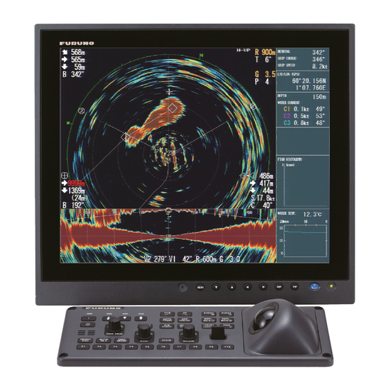
NUMERIC/GRAPHIC DATA DIS- PLAY Numeric/Graphic Data Display This display provides comprehensive numeric/graphic data and appears with the hor- izontal and vertical displays, at the right side of the display. ° Heading* HEADING Course* ° SHIP COURSE 12.5kn Speed* SHIP SPEED Position format LAT/LON[DGPS] Navigator type (in brackets)*... -
Page 126: Numeric, Graphic Data Description
5. NUMERIC/GRAPHIC DATA DISPLAY Numeric, Graphic Data Description When a data is lost its last-entered value is shown in red. Data displays can be turned on or off through the [DATA DISPLAY] menu. Numeric/ Available Description Display range Where to change format Graphic item formats Heading... - Page 127 5. NUMERIC/GRAPHIC DATA DISPLAY Numeric/ Available Description Display range Where to change format Graphic item formats Fish histo- Shows signal Two marks On/Off on the [Mark Display]- [Histogram gram strength con- Disp.] menu centration of fish estimate mark inscribed on hor- izontal display, slant display Water temp.
- Page 128 5. NUMERIC/GRAPHIC DATA DISPLAY This page is intentionally left blank.
-
Page 129: How To Customize The Equipment
HOW TO CUSTOMIZE THE EQUIPMENT User Menu You may program 20 often-used menu items to the user menu area in the menu. The default user menu contains, for the horizontal display, pulse length, TX power, TVG near, TVG medium, TVG far, AGC, 2nd AGC, echo average, color and echo average. Push the Push the left-click button. -
Page 130: How To Delete Items From The User Menu
6. HOW TO CUSTOMIZE THE EQUIPMENT 4. Select [Register] then push the left-click button. The selected item is registered, and shown at the bottom of the menu. The order of items in the [USER] menu can be changed by drag and drop. Note: If 20 items are already registered to the user menu the following message appears. -
Page 131: How To Execute A Program
6. HOW TO CUSTOMIZE THE EQUIPMENT 6.2.1 How to execute a program 1. Press desired function key to show the applicable dialog box. When the F8 key is pressed 2. Press the same function key again within five seconds to execute the function. The dialog box automatically disappears in five seconds. -
Page 132: How To Erase Programs
6. HOW TO CUSTOMIZE THE EQUIPMENT 6.2.3 How to erase programs 1. Press the MENU/ESC key to open the main menu. 2. Select [Others] then push the left-click button. 3. Select [Register] then push the left-click button. 4. Select [Clear F-KEY Setting] then push the left-click button. 5. -
Page 133: User Prog Control
6. HOW TO CUSTOMIZE THE EQUIPMENT 2. Press the MENU/ESC key to close the menu. 3. Press and hold down the applicable key of the control unit and then press a func- tion key of the remote controller. When the registration is completed, the audio alarm sounds. 4. -
Page 134: How To Program Display Ranges
6. HOW TO CUSTOMIZE THE EQUIPMENT *: H/V Interlock: Effective on both H and V displays. H/V Individual: Select the display to use with the H/V/S key. (In operative on the slant display). 5. Do one of the following then push the left-click button. •... -
Page 135: Others Menu
OTHERS MENU This chapter provides descriptions for the [Others] menu. To display the [Others] menu, press the MENU/ESC key, select [Others] then push the left-click button. The [Record/Recall] menu is described in Chapter 8. Also, menu items shown in gray cannot be accessed. -
Page 136: Wheel Setting Menu
7. OTHERS MENU Wheel Setting Menu One of the following functions can be assigned to the scrollwheel. • Tilt angle • Gain • Range • Turn Angle (Slant display only) • Bearing (Vertical display only) 1. Select [Wheel Setting] on the [Other] menu then push the left-click button. This menu can be also opened from the pop-up menu. -
Page 137: Display Setting Menu
7. OTHERS MENU Display Setting Menu The [Display Setting] menu sets various display-related items according to operator’s preference. To display the menu, open the main menu then select the [Others] and [Display Setting] menus. TX/RX Mode: Select how to transmit and receive in combination displays. [Alternative] executes Tx and Rx one display at a time. - Page 138 7. OTHERS MENU H2/S Display: Selects the combination mode of horizontal and slant displays: Land- scape, Portrait, or Inset. 2nd Monitor Setting: When two monitors are connected, select the combination mode for the sub-display; Landscape or Portrait. This function is available only when [Dual Display] is selected at [2nd Monitor Setting] on [Others]-[Initial Setting] menu.
-
Page 139: Alarm & Audio Menu
7. OTHERS MENU Alarm & Audio Menu The [Alarm & Audio] menu sets the fish alarm and the audio bearing mark sector. To show this menu, open the main menu, then open the [Others] and [Alarm & Audio] menus. Fish Alarm: Turns the fish alarm function on or off. The default setting is off. Alarm Level: Sets the minimum echo color which triggers the fish alarm. -
Page 140: Register Menu
7. OTHERS MENU Register Menu The [Register] menu provides various programming functions. To show this menu, se- lect [Register] on [Others] menu then push the left-click button. [Sel User Prog] = [H/V Interlock] Sel User Prog/Assign User Prog/Auto User Prog Sel/Auto User Prog: Programs the USER PROG control. -
Page 141: Initial Setting Menu
7. OTHERS MENU Initial Setting Menu The [Initial Setting] menu sets up mark size, current vector, net sonde, target lock, etc. 1. Press the MENU/ESC key to show the main menu. 2. Select [Others] then push the left-click button. 3. Select [Initial Setting] then push the left-click button. 4. - Page 142 7. OTHERS MENU Monitor Setting menu The [Monitor Setting] menu sets the function of dual monitors. Select [Monitor Setting] on the [Initial Setting] menu then push the left-click button. 2nd Monitor Setting: Selects the display format for the sub monitor (Off, Dual Dis- play, Sub Display).
- Page 143 7. OTHERS MENU Mark Display menu The [Mark Display] menu turns on/off marks. Select [Mark Display] on the [Initial Set- ting] menu then push the left-click button. Heading Mark: The heading mark is a dashed line which indicates the heading in all presentation modes. It extends from own ship position to the outer edge of the display and Heading appears at zero degrees in the head-up mode.
- Page 144 7. OTHERS MENU Data On Track: Shows depth or water temperature on the ship’s track. Track Depth (or water temperature) Net Move Plot: Shows predicted net movement against Own ship’s three current layers over time. Automatically turned on or track off with the net shoot mark.
- Page 145 7. OTHERS MENU Mark Size menu The [Mark Size] menu lets you select the size and shape of the marks. Select [Mark Size] on the [Initial Setting] menu then push the left-click button. Trackball Mark: Selects size and appearance of cursor. The choices are large and small “+”...
- Page 146 7. OTHERS MENU Data Display menu This menu turns on/off alphanumeric data. Select [Data Display] on the [Initial Setting] menu then push the left-click button. Range/Bearing: Turns on/off the range and bearing data which appears when the range/bearing marks are turned on. Fishing Area: Not used.
- Page 147 7. OTHERS MENU Current Vec & Wind menu The [Current Vec & Wind] menu sets up tidal current and wind data. Select [Current/ Wind] on [Initial Setting] menu then push the left-click button. Current Data: Selects how to display current data; absolute or in relation to layer 1, layer 2 or layer 3.
- Page 148 7. OTHERS MENU Net SONDE Setting menu The [Net SONDE Setting] menu sets up the net sonde. Select [Net SONDE Setting] on [Initial Setting] then push the left-click button. *Setting cannot be adjusted after the net is thrown. Number Of XMTR: Sets number of transmitter units used, from 0-10. When the total value of [XMTR Distance] is smaller than the setting value of [Net Length], max.
- Page 149 Pitch Angle Cor: Offsets the pitch angle error generated by the motion sensor. Roll Angle Cor: Offsets the roll angle error generated by the motion sensor. Sensor: Select the type of the motion sensor used, FURUNO motion sensor or GPS gyro (satellite compass).
- Page 150 7. OTHERS MENU Initialization menu Select [Initialization] on [Initial Setting] menu then push the left-click button to show the [Initialization] menu. Save Ship/Org: All menu settings are saved. Recall Ship/Org: Recalls the saved menu settings. Default settings are memorized in the internal memory.
-
Page 151: Record/Recall Operation
RECORD/RECALL OPERATION You can take still images of the display and store them internally. How to Specify Where to Save Still Images You can specify where to save still images as follows: 1. Push the right-click button on the numeric/graphic data display to show the pop- up menu. -
Page 152: How To Save Still Image
8. RECORD/RECALL OPERATION 6. Select [OK] then push the left-click button. 7. Long-press the MENU/ESC key to close all menus. How to Save Still Image You can save the picture on the display as a still image. Single display 1. Push the right-click button on the numeric/graphic data display to show the pop- up menu. - Page 153 8. RECORD/RECALL OPERATION How to display the latest still image 1. Push the right-click button on the numeric/graphic data display to show the pop- up menu. 2. Select [Record/Recall] then push the left-click button. 3. Select [Recall Still Image] then push the left-click button. The latest still image is shown on the display.
-
Page 154: How To Save Settings
8. RECORD/RECALL OPERATION How to Save Settings The FSV-85 can store the setting information in use as shown below. 1. Push the right-click button on the numeric/graphic data display to show the pop- up menu. 2. Select [Record/Recall] then push the left-click button. -
Page 155: How To Load Files
8. RECORD/RECALL OPERATION How to Load Files 8.5.1 How to load the setting information This section shows you how to load the setting information saved at section 8.4. 1. Push the right-click button on the numeric/graphic data display to show the pop- up menu. -
Page 156: How To Replay Setting Information
8. RECORD/RECALL OPERATION 8.5.2 How to replay setting information You may want to replay setting information to set up the equipment according to target fish or fishing ground. 1. Push the right-click button on the numeric/graphic data display to show the pop- up menu. -
Page 157: How To Delete Files
8. RECORD/RECALL OPERATION How to Delete Files You can delete unnecessary files as shown below. 1. Push the right-click button on the numeric/graphic data display to show the pop- up menu. 2. Select [Record/Recall] then push the left-click button. 3. Select [Delete Data] then push the left-click button. Destination list 4. - Page 158 8. RECORD/RECALL OPERATION This page is intentionally left blank.
-
Page 159: Maintenance, Troubleshooting
MAINTENANCE, TROUBLE- SHOOTING This chapter provides maintenance and troubleshooting procedures for the operator. NOTICE WARNING o not apply paint, anti-corrosive ELECTRICAL SHOCK HAZARD Do not open the equipment. sealant or contact spray to plastic parts or equipment coating. This equipment uses high voltage that can cause Those items contain products that can electrical shock. -
Page 160: Hull Unit Maintenance
9. MAINTENANCE, TROUBLESHOOTING Hull Unit Maintenance Care for the hull unit by following the procedures shown below. Apply MOLYTONE grease #2 every six months. Raise transducer and coat main shaft with Daphne Eponex Grease No.2 (IDEMITSU KOSAN CO.,LTD.* every six months. Dry dock ship and clean transducer face yearly. -
Page 161: How To Replace Fuses
9. MAINTENANCE, TROUBLESHOOTING How to Replace Fuses The fuses in the processor unit, transceiver unit and hull unit protect them from over- current and equipment fault. If the power cannot be applied, first check the fuse in the processor unit and transceiver unit. If the power still cannot be turned on, have a qual- ified technician check the fuses in other units. -
Page 162: How To Clean The Filter In The Processor Unit
9. MAINTENANCE, TROUBLESHOOTING How to Clean the Filter in the Processor Unit Clean the filter in the Processor Unit when the filter becomes dusty. Remove the filter and clean it with water and a mild detergent. Let the filter dry then set it to the Proces- sor Unit. -
Page 163: Troubleshooting
9. MAINTENANCE, TROUBLESHOOTING Troubleshooting The table below provides common symptoms of equipment troubles and the means to rectify them. Troubleshooting Symptom Check, remedy Cannot turn on power. • Check cables between transceiver unit, processor unit and monitor unit. • Check ship’s mains. •... -
Page 164: Warning Messages
9. MAINTENANCE, TROUBLESHOOTING Warning Messages The table below shows the warning messages which may appear on the display. All warning messages are accompanied by an audio alarm, which you may silence with the R/B AUDIO key. Warning messages Message Meaning, Remedy Power supply <<OVERVOLTAGE!! >>... -
Page 165: Error Codes
9. MAINTENANCE, TROUBLESHOOTING Message Meaning, Remedy <<WARNING!!>> TRANSDUCER IS KEPT AT This message blinks at the screen center and the WRONG POSITION. SET BACK TRANSDUC- buzzer sounds when the transducer is knocked ER POSITION TO NORMAL BY USING ↑ OR ↓ out of position. -
Page 166: Status Messages
9. MAINTENANCE, TROUBLESHOOTING 9.10 Status Messages Status messages appear at the screen center to alert the operator. These are as be- low. Status messages and their meanings Status message Meaning TX OFF Transmission turned off from the menu. RAISE/LOWER TEST* Raise/lower command received from the control unit in normal opera- tion, to manually test raise/lower switch in hull unit. -
Page 167: Board Test
9. MAINTENANCE, TROUBLESHOOTING 9.11.2 Board test The board test checks all the circuit boards in the system. Select [Board Test] from the [Test] menu to do this test. BOARD TEST 105-0830-XX.XX MPU-001-FSV85 105- 0839-XX.XX TRCPU-0 S2 00000000 S3 00000000 105-0826-XX.XX = Enable = OK = OK... -
Page 168: Panel Test
9. MAINTENANCE, TROUBLESHOOTING 9.11.3 Panel test The panel test checks the keys, controls and trackball of the control unit. Select [Panel Test] from the [Test] menu to do this test. PANEL TEST X = 0 Y = 0 d = 0 X = 0 Y = 0 d = 0... -
Page 169: Test Pattern
9. MAINTENANCE, TROUBLESHOOTING 9.11.4 Test pattern The test pattern test checks for proper display of colors. Select [Test Pattern] from the [Test] menu to do this test. Use the MODE key to change the test pattern. PRESS MENU KEY TO QUIT TEST MODE. PRESS MODE KEY TO CHANGE TEST PATTERN. -
Page 170: How To Raise The Transducer Automatically
9. MAINTENANCE, TROUBLESHOOTING 9.12.1 How to raise the transducer automatically 1. Turn off the switchboard, transceiver unit and hull unit from the ship’s mains breaker. You can force-quit the system by long-pressing the POWER OFF ( ) switch for approx. 10 seconds. 2. -
Page 171: How To Raise The Transducer Manually
9. MAINTENANCE, TROUBLESHOOTING 9.12.2 How to raise the transducer manually 1. Open the lid on the raise/lower control box of the hull unit and turn off the motor breaker. Confirm that the power lamp is off. (See the illustration above for location of motor breaker and power lamp.) 2. - Page 172 9. MAINTENANCE, TROUBLESHOOTING This page is intentionally left blank. 9-14...
-
Page 173: Appendix 1 Menu Tree
APPENDIX 1 MENU TREE [MENU/ESC] key TX/RX Setting TX Interval (External KP, 1 to 9; 9) [H1/H2/S], U: Yes/F: Yes U: Items which can be U: No /F: Yes TX Pulse Length (0 to 9; 7) [H1/H2/S/V], U: Yes/F: Yes programmed to the user menu. - Page 174 APPENDIX 1 MENU TREE Picture Setting Echo Average (0 to 7; 2) [H1/H2/S/V], U: Yes/F: Yes U: No/F: Yes Int Reject (0 to 3; 0) [H1/H2/S/V], U: Yes/F: Yes Smooth Echo RNG (0 to 7; 3) [H1/H2/S/V], U: Yes/F: Yes Smooth Echo CIR (0 to 5;...
- Page 175 APPENDIX 1 MENU TREE Others Record/Recall Still Image, U: Yes/F: Yes U: No/F: Yes Setting File, U: No/F: Yes Save, U: No/F: No Load, U: No/F: No Load User Prog., U: No/F: No Delete Data, U: No/F: No Destination To Save, U: No/F: No Record Still Image (Execute), U: No/F: Yes Recall Still Image (Display), U: No/F: Yes Initial Setting...
- Page 176 APPENDIX 1 MENU TREE Others Initial Setting Current Vec & Wind, U: No/F: Yes Current Data (Water Current, Rel to Layer1, Rel to Layer2, Rel to Layer3), U: No/F: Yes On Own Ship Mark (OFF, ON), U: No/F: No On Ship Pos Mark (OFF, ON), U: No/F: No On Net Shoot Mark (OFF, ON), U: No/F: No Current Flow Dir (To, From), U: No/F: No Wind (OFF, Relative, Absolute)
- Page 177 APPENDIX 1 MENU TREE Others Initial Setting Test, U: No/F: Yes Board Test (Execute), U: No, F: No Panel Test (Execute), U: No, F: No Test Pattern (Execute), U: No, F: No RX Test (Execute), U: No, F: No Noise Test (Execute), U: No, F: No TX (OFF, ON), U: Yes/F: Yes Initialization, U: No/F: Yes Save Ship's Org (Execute), U: No, F: No...
- Page 178 APPENDIX 1 MENU TREE This page is intentionally left blank. AP-6...
-
Page 179: Specifications
FURUNO FSV-85 SPECIFICATIONS OF COLOR SCANNING SONAR FSV-85 GENERAL Scanning method Full digital beam forming Frequency 70 or 80 kHz Range and Pulse-length Basic Range (m) Basic Range (m) range range Off-center Off-center Off-center Off-center ’OFF’ ‘ON’ ’OFF’ ‘ON’ 0-60... - Page 180 FURUNO FSV-85 HULL UNIT Motion sensor Raise/lower Ship’s speed allowance Travel (mm) time (sec) (at R/L operation) attached blank 500/800 FSV-8x31/32 FSV-8x33/34 18 kn 800/1100 FSV-8x41/42 FSV-8x43/44 (15 kn) x: 4 or 5. FSV-8431 series for 80kHz, FSV-8531 series for 70kHz.
-
Page 181: Index
INDEX Numerics color setting, vertical display ....3-17 Concentration of school of fish 2nd AGC horizontal display........2-29 horizontal display ........2-13 slant display .......... 4-24 slant display ..........4-9 Control description ........1-1 vertical display........3-10 CURRENT & VEC WIND menu ....7-13 2nd AGC distance horizontal display ........ - Page 182 INDEX programming ..........6-3 OTHERS menu ..........7-1 Fuse replacement ........9-3 horizontal display ........2-38 slant display ...........4-31 vertical display........3-16 GAIN control ..........1-11 Own ship position mark Gain offset entering, horizontal display ....2-35 horizontal display ........2-38 slant display ...........4-32 vertical display........3-16 Panel dimmer ..........1-5 Panel test ..........9-10 Post 2nd AGC Heading mark..........7-9...
- Page 183 INDEX Target lock slant display .......... 4-11 dimensions, horizontal display ....2-24 TX pulse length dimensions, slant display ...... 4-19 horizontal display........2-14 fish mode, horizontal display ....2-22 slant display .......... 4-10 fish track plot ......... 7-10 vertical display........3-11 mark interlock, horizontal display ..