Lennox SLP98UHV Installation Instructions Manual
Collection gas furnace upflow / horizontal air discharge
Hide thumbs
Also See for SLP98UHV:
- Unit information (70 pages) ,
- Installation instructions manual (67 pages) ,
- User manual (41 pages)
Table of Contents
Advertisement
E 2012 Lennox Industries Inc.
Dallas, Texas, USA
HORIZONTAL LEFT
WARNING
Improper installation, adjustment, alteration, service
or maintenance can cause property damage, person-
al injury or loss of life. Installation and service must
be performed by a licensed professional installer (or
equivalent), service agency or the gas supplier.
. . . . . . . . . . . . . . . . . . . . . . . . . . . . . . . . .
. . . . . . . . . . . . . . . . . . . . . . . . . . . . . .
. . . . . . . . . . . . . . . . . . . . . . . . . . . . . . . . . . . .
. . . . . . . . . . . . . . . . . . . . . . . . . . . . . . .
. . . . . . . . . . . . . . . . . . . . . . . . . . . . . . . . . . . . . . . .
. . . . . . . . . . . . . . . . . . . . . . . . . . . . . . .
. . . . . . . . . . . . . . . . . . . . . . . . . . . . . . . . . . . . . . . . .
. . . . . . . . . . . . . . . . . . . . . . . . . . . . . . . . . . .
. . . . . . . . . . . . . . . . . . . . . . . . . . . . . . .
. . . . . . . . . . . . . . . . . . . . . . . . . .
06/12
*2P0612*
AIR FLOW
UPFLOW
HORIZONTAL RIGHT
Table of Contents
. . . . . . . . . . . . . . . . . . . . . . . .
. . . . . . . . . . .
. . . . . . . . . . . . . . . . . . .
. . . . . . . . . . . . . . . . . . . . . .
INSTALLATION
INSTRUCTIONS
SLP98UHV
DAVE LENNOX SIGNATURE
COLLECTION GAS FURNACE
UPFLOW / HORIZONTAL AIR DISCHARGE
507026−01
06/2012
Supersedes 506610−01
THIS MANUAL MUST BE LEFT WITH THE
HOMEOWNER FOR FUTURE REFERENCE
This a safety alert symbol and should never be ignored.
When you see this symbol on labels or in manuals, be alert
to the potential for personal injury or death.
As with any mechanical equipment, personal injury
can result from contact with sharp sheet metal
edges. Be careful when you handle this equipment.
A thermostat is not included and must be ordered
separately.
D The Lennox icomfort Touch
used in communicating applications.
D In non−communicating applications, the Lennox
ComfortSense
well as other non−communicating thermostats.
In all cases, setup is critical to ensure proper sys-
tem operation.
Field wiring for both communicating and non−com-
municating applications is illustrated in diagrams,
which begin on Page 33.
2
. . . . . . . . . . . . . . . . . . . . . . . . . . . . . . . . . . . .
. . . . . . . . . . . . . . . . . . . . . . . . . . . . . . . . . . . . . .
3
4
4
. . . . . . . . . . . . . . . . . . . . . . . . . . . . . . . . . . .
4
5
6
6
10
11
. . . . . . . . . . . . . . . . . . . . . . . . . . . . . . . . . . . . . . .
11
12
13
13
Page 1
®
CAUTION
NOTICE
®
thermostat must be
®
7000 thermostat may be used, as
. . . . . . . . . . . . . . . . . . . . . . . . . . . . . .
. . . . . . . . . . . . . . . . . . . . . . .
. . . . . . . . . . . . . . . . . . . . .
. . . . . . . . . . . . . . . . . . . . . . . .
. . . . . . . . . . . . . . . . . . . . . . . . . . . . .
. . . . . . . . . . . . . . . . . . . . . . . . . .
. . . . . . . . . . . . . . . . . .
. . . . . . . . . . . . . . . . . . . . . . . . . . . . . . .
. . . . . . . . . . . . . .
. . . . . . . . . . . . . . . . . . . . .
. . . . . . . . . . . . . . . . . . . . . . . . . . . . . . . .
507026−01
*P507026-01*
Litho U.S.A.
28
31
39
43
48
49
51
51
51
52
54
55
56
59
60
Advertisement
Table of Contents

Related Manuals for Lennox SLP98UHV


Summary of Contents for Lennox SLP98UHV
-
Page 1: Table Of Contents
D The Lennox icomfort Touch ® thermostat must be used in communicating applications. HORIZONTAL RIGHT HORIZONTAL LEFT D In non−communicating applications, the Lennox ® ComfortSense 7000 thermostat may be used, as WARNING well as other non−communicating thermostats. In all cases, setup is critical to ensure proper sys- Improper installation, adjustment, alteration, service tem operation. -
Page 2: Unit Dimensions
Unit Dimensions − inches (mm) EXHAUST AIR 3−1/4 NOTE − 60C and 60D size units that require second stage OUTLET (83) air volumes over 1800 cfm (850 L/s) must have one of the following: 1−7/8 (48) 1. Single side return air with transition, to accommodate 20 x 25 x 1 in. -
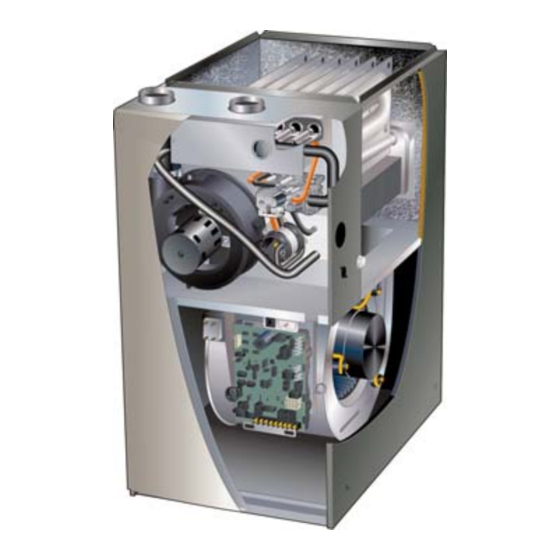
Page 3: Parts Arrangement
Parts Arrangement BURNER BOX ASSEMBLY PRESSURE SWITCHES HEAT EXCHANGER VARIABLE CAPACITY PRIMARY LIMIT GAS VALVE VARIABLE SPEED COMBUSTION AIR INDUCER BAG ASSEMBLIES (shipping location) COLD END HEADER ACCESS PANEL VARIABLE SPEED BLOWER MOTOR SHIPPING BLOCK (−135 UNITS ONLY) SIGHT GLASS INNER BLOWER ACCESS PANEL CONTROL BOX... -
Page 4: Gas Furnace
The furnace is equipped for installation in natural gas ap- plications only. A changeover kit may be ordered for LP applications. WARNING The SLP98UHV must be installed only as a Direct Vent gas furnace. Improper installation, adjustment, alteration, service NOTE − In Direct Vent installations, combustion air is taken or maintenance can cause property damage, person- from outdoors and flue gases are discharged outdoors. -
Page 5: Use Of Furnace As A Construction Heater
This SLP98UHV furnace must be installed so that its elec- CAUTION trical components are protected from water. Do not set thermostat below 60°F (16°C) in heating Installed in Combination with a Cooling Coil mode. -
Page 6: General
P.O. Box 799900 Dallas, TX 75379−9900 CAUTION Front Back SLP98UHV unit should not be installed in areas nor- mally subject to freezing temperatures. FIGURE 4 These instructions are intended as a general guide and do Upflow Applications not supersede local codes in any way. Consult authorities The SLP98UHV gas furnace can be installed as shipped having jurisdiction before installation. -
Page 7: Setting Equipment
Transition Screw FIGURE 6 Bottom Cap SLP98UHV applications which include side return air and a condensate trap installed on the same side of the Bottom Panel cabinet (trap can be installed remotely within 5 feet) re- quire either a return air base or field−fabricated transi-... - Page 8 Optional Return Air Base CONDENSATE (Upflow Applications Only) TRAP FURNACE FRONT 23 (584) 3−1/4 IF BASE Overall (83) IS USED (Maximum) Minimum WITHOUT 11 (279) IAQ CABINET, Maximum INDOOR AIR 22−7/16 A SINGLE Unit side return air 14 (356) (570) QUALITY RETURN AIR Opening...
- Page 9 12, or install the furnace on a platform, as shown in figure 13. A horizontal suspension Refer to Engineering Handbook for additional information. kit (51W10) may be ordered from Lennox or use equiva- Setting an Upflow Unit lent.
-
Page 10: Filters
NOTE − When the furnace is installed on a platform in a 6 − Continue with exhaust, condensate and intake piping crawlspace, it must be elevated enough to avoid water installation according to instructions. damage and to allow the evaporator coil to drain. *GAS CONNECTION INTAKE PIPE HORIZONTAL SUSPENSION KIT... -
Page 11: Duct System
If a filter is installed, size the re- SLP98UHV exhaust and intake connections are turn air duct to fit the filter frame. made of PVC. Use PVC primer and solvent cement when using PVC vent pipe. -
Page 12: Joint Cementing Procedure
TABLE 3 OUTDOOR TERMINATION USAGE STANDARD CONCENTRIC Flush- Wall Kit Wall Ring Kit 1−1/2 inch 2 inch 3 inch Mount Vent 2 inch 3 inch 2 inch Pipe Input Size Field Dia. in. 71M80 69M29 Fabricated 44J40 22G44 (US) (US) (US) 60L46 (US) (US) -
Page 13: Venting Practices
REPLACING FURNACE THAT WAS PART OF A COMMON VENT SYSTEM Vent Piping Guidelines CHIMNEY OR GAS VENT The SLP98UHV is installed only as a Direct Vent gas (Check sizing for water central furnace. heater only) NOTE − In Direct Vent installations, combustion air is taken from outdoors and flue gases are discharged outdoors. - Page 14 TABLE 4 length. Includes all vent MINIMUM VENT PIPE LENGTHS pipe and elbows inside MIN. EQUIV. SLP98UHV and outside the house. VENT EXAMPLE MODEL LENGTH 5 ft. plus 2 elbows of 2", 2−1/2"...
- Page 15 TABLE 5 Maximum Allowable Intake or Exhaust Vent Length in Feet *Size intake and exhaust pipe length separately. Values in table are for Intake OR Exhaust, not combined total. Both Intake and Exhaust must be same pipe size. NOTE − Additional vent pipe and elbows used to terminate the vent pipe outside the structure must be included in the total vent length calculation. Standard Termination at Elevation 0 −...
- Page 16 TYPICAL EXHAUST AND INTAKE PIPE CONNECTIONS IN UPFLOW APPLICATIONS Intake Exhaust Intake Exhaust 2” 2” 2” 2” 2” 2” *2” *2” DO NOT transition from smaller to larger pipe size in horizontal runs of exhaust pipe. * When transitioning up in pipe size, use the shortest length of 2” PVC pipe possible. FIGURE 18 TYPICAL EXHAUST AND INTAKE PIPE CONNECTIONS IN HORIZONTAL AIR APPLICATIONS (RIGHT HAND DISCHARGE SHOWN)
-
Page 17: Vent Termination Clearances
‡ Permitted only if veranda, porch, deck or balcony is fully open on a minimum of two sides beneath the floor. Lennox recommends avoiding this location if possible. FIGURE 20 Page 17... - Page 18 (19mm) Armaflex or equivalent may be necessary. Insula- doors. The SLP98UHV is classified as a direct vent, Cate- tion on outside runs of exhaust pipe must be painted or gory IV gas furnace.
- Page 19 TABLE 7 See table 7. EXHAUST PIPE TERMINATION SIZE REDUCTION NOTE − Care must be taken to avoid recirculation of SLP98UHV Termination Pipe Size MODEL exhaust back into intake pipe. *070 1−1/2"...
- Page 20 7 − If intake and exhaust piping must be run up a side wall equipped with a 90° elbow turndown. Using turndown to position above snow accumulation or other ob- will add 5 feet (1.5m) to the equivalent length of the structions, piping must be supported every 24"...
- Page 21 FIELD−FABRICATED WALL TERMINATION OR FIELD−FABRICATED WALL TERMINATION OR (15F74) WALL RING TERMINATION KIT (15F74) WALL RING TERMINATION KIT With INTAKE ELBOW NOTE − FIELD−PROVIDED REDUCER MAY BE NOTE − FIELD−PROVIDED 1/2" (13mm) ARMAFLEX REQUIRED TO ADAPT REDUCER MAY BE INSULATION IN UN- 1/2"...
- Page 22 EXHAUST VENT Front View 1 1/2" (38mm) accelerator provided with 71M80 & SIZE 44W92 kits for TERMINATION SL98UH070V36B PIPE PER INTAKE TABLE 7. FLASHING 12” (305mm) INTAKE (Not Furnished) Minimum Above Average Top View Snow Accumulation 1/2" (13mm) Foam Insulation in Unconditioned Space EXHAUST VENT SHEET METAL STRAP...
- Page 23 WALL TERMINATION KITS (CLOSE−COUPLE) EXTENDED VENT FOR GRADE CLEARANCE 2 inch (51 mm) 22G44 (US) 3 inch (76 mm) 44J40 (US) If intake and exhaust pipe is less than 12 in. (305 mm) above snow accumulation or other obstructions, FIELD−PROVIDED field−fabricated piping must be installed.
- Page 24 CONDENSATE TRAP AND PLUG LOCATIONS SLP98 DIRECT VENT APPLICATION (Unit shown in upflow position) USING EXISTING CHIMNEY STRAIGHT−CUT OR ANGLE−CUT IN DIRECTION OF ROOF SLOPE * 3" − 8" EXHAUST VENT (76mm− 8" − 12" 1/2" (13mm) 203mm) (203mm − 305mm) WEATHERPROOF INSULATION 1−1/2 in.
- Page 25 If this is not possible, a heat cable kit may be used on the condensate trap and line. Heating cable kit is available from Lennox in various lengths; 6 ft. (1.8m) − kit no. 26K68; 24 ft. (7.3m) − kit no. 26K69; and 50 ft.
- Page 26 HorizontalFurnace4” Min. to 5” Max.above condensatedrain connection) FurnaceCondensate Drain Connection Optional FIGURE 41 FIGURE 40 SLP98UHV with Evaporator Coil Using a Common Drain (Unit shown in horizontal left−hand discharge position) (4” min. to 5” Max.above Evaporator condensatedrain connection) Coil 4”min 5”max...
- Page 27 TRAP / DRAIN ASSEMBLY USING 1/2" PVC OR 3/4" PVC Optional Condensate Drain Connection Adapter 3/4 inch slip X 3/4 inch mpt (not furnished) 90° Street Elbow 3/4 inch PVC (not furnished) Adapter 3/4 inch slip X 3/4 inch mpt (not furnished) Condensate Drain Connection In Unit 1 (25 mm) Min.
-
Page 28: Gas Piping
Gas Piping IMPORTANT CAUTION Compounds used on threaded joints of gas piping must be resistant to the actions of liquified petro- leum gases. If a flexible gas connector is required or allowed by the authority that has jurisdiction, black iron pipe shall be installed at the gas valve and extend outside the furnace cabinet. - Page 29 Upflow Application Upflow Application Left Side Piping Right Side Piping 1/2" NPT (Standard) (Alternate) 1/2" NPT MANUAL MAIN SHUT−OFF VALVE MANUAL MAIN SHUT−OFF VALVE GROUND GROUND JOINT JOINT UNION UNION DRIP LEG FIELD PROVIDED AND INSTALLED DRIP LEG NOTE − BLACK IRON PIPE ONLY TO BE ROUTED INSIDE OF CABINET FIGURE 45 Horizontal Applications Possible Gas Piping Configurations...
- Page 30 Removal of the Furnace from Common Vent 3 − Close all building doors and windows and all doors be- tween the space in which the appliances remaining In the event that an existing furnace is removed from a connected to the common venting system are located venting system commonly run with separate gas ap- and other spaces of the building.
-
Page 31: Electrical
MAKE−UP connections. NOTE − Do NOT make a wire connection between the room thermostat L terminal and the L terminal of the SLP98UHV integrated control unless this is a communicating thermostat installation with a non− communicating outdoor unit. Right Side 6 −... - Page 32 º º rating 95 F (35 C) mini- 2 − When the SLP98UHV is running in the heating mode, mum, solid core. (Class II More than 100’ (30m) Rated Wiring) the integrated control will automatically adjust the blower speed to match the furnace firing rate. This TABLE 12 speed can be adjusted up or down by 7.5% or 15% us-...
- Page 33 Non−Communicating Outdoor Unit and icomfortt−ENABLED Outdoor Unit ® icomfort Touch Thermostat ® icomfort Touch Thermostat icomfortt−Enabled SLP98UHV Indoor Furnace icomfortt−Enabled SLP98UHV Indoor Furnace Non−Communicating Outdoor Air Conditioner icomfortt−Enabled Outdoor Air Conditioner or Heat Pump icomfortt− ENABLED icomfortt− SLP98UHV ENABLED...
- Page 34 System icomfortt− NOTE: icomfortt THERMOSTAT SENSES HUMIDITY & CONTROLS ENABLED 24V H" OUTPUT (& 120V H" OUTPUT) TO CYCLE HUMIDIFIER SLP98UHV BASED ON DEMAND. NO OTHER CONTROL OR HUMIDISTAT FURNACE REQUIRED. OPTIONAL OUTDOOR AIR SENSOR FOR USE WITH HU- MIDIFIER (IF NOT ALREADY IN THE SYSTEM FOR OTHER FUNCTIONS.
- Page 35 TABLE 13 Field Wiring Connections for Non−Communicating Thermostat Applications DIP Switch Settings and On−Board Links (figure 51) W914 W915 (DS to R) W951 (Y1 to Y2) Dehumidifi- Thermostat Wiring Connections DIP Switch 1 (O to R) Two−Stage cation or Heat Pumps Cooling Harmony IIIt...
- Page 36 TABLE 13 Field Wiring for Non−Communicating Applications (Continued) DIP Switch Settings and On−Board Links (figure 51) W914 W915 (DS to R) (Y1 to Y2) W951 Dehumidifi- Thermostat Wiring Connections DIP Switch 1 Two−Stage (O to R) cation or Cooling Heat Pumps Harmony IIIt 2 Heat / 2 Cool...
- Page 37 * Connect W1 to W1 ONLY if using defrost tempering kit 67M41. NOTE − Do NOT make a wire connection between the room thermostat L terminal and the L terminal of the SLP98UHV integrated control. Page 37...
- Page 38 TYPICAL SLP98UHV WIRING DIAGRAM FIGURE 50 Page 38...
-
Page 39: Integrated Control
Integrated Control NEUTRAL TERMINALS COMBUSTION AIR INDUCER CONNECTOR IGNITOR CONNECTOR FLAME SENSE DIAGNOSTIC LINE VOLTAGE PUSH BUTTON TERMINALS DIP SWITCHES OUTDOOR AIR INDOOR SENSOR BLOWER TERMINALS 7−SEGMENT CONNECTOR DIAGNOSTIC LED W915 Y1 TO Y2 DISCHARGE AIR SENSOR W951 R TO O TERMINALS W914 R TO DS FACTORY TEST... - Page 40 10 minutes fixed Two−Stage Heat (W1 70%, W2 100%) Two−Stage NOTE − When the SLP98UHV is used with an icomfort and 5 on the integrated control. The unit is shipped from the Toucht communicating thermostat, all indoor blower factory with a blower−off delay of 90 seconds. The blower−...
- Page 41 Switches 8 and 9 −− Cooling Mode Blower Speed −− The TABLE 19 Cooling Mode Blower Speed Ramping unit is shipped from the factory with the DIP switches posi- Ramping Option Switch 12 Switch 13 tioned for high speed (4) indoor blower motor operation A (Factory) during the cooling mode.
- Page 42 Refer to table 22 for operation sequence in ap- form the high−fire and low−fire pressure switch calibra- plications including SLP98UHV, a thermostat which fea- tions and display CAL". After calibration, the LED will tures humidity control and a single−speed outdoor unit.
-
Page 43: Blower Motor Performance
First stage COOL (two-stage air conditioning units only) is approximately 70% of the same second stage COOL speed position. Continuous Fan speeds are approximately 28%, 38%, 70% and 100% (DIP switch selectable) of the same second-stage COOL speed position minimum 300 cfm. Lennox Harmony III™ Zoning System Applications - Minimum blower speed is 250 cfm. Page 43... - Page 44 First stage COOL (two-stage air conditioning units only) is approximately 70% of the same second stage COOL speed position. Continuous Fan speeds are approximately 28%, 38%, 70% and 100% (DIP switch selectable) of the same second-stage COOL speed position minimum 300 cfm. Lennox Harmony III™ Zoning System Applications - Minimum blower speed is 380 cfm. Page 44...
- Page 45 First stage COOL (two-stage air conditioning units only) is approximately 70% of the same second stage COOL speed position. Continuous Fan speeds are approximately 28%, 38%, 70% and 100% (DIP switch selectable) of the same second-stage COOL speed position minimum 300 cfm. Lennox Harmony III™ Zoning System Applications - Minimum blower speed is 450 cfm. Page 45...
- Page 46 TABLE 22 COOLING OPERATING SEQUENCE SLP98UHV and Single−Stage Outdoor Unit OPERATING SYSTEM DEMAND SYSTEM RESPONSE SEQUENCE Demand Relative Humidity Blower System Step Compressor Comments Condition Status (COOL) stage NO CALL FOR DEHUMIDIFICATION Compressor and indoor Normal Operation Acceptable High 100%...
- Page 47 TABLE 23 COOLING OPERATING SEQUENCE SLP98UHV and Two−Stage Outdoor Unit OPERATING SYSTEM DEMAND SYSTEM RESPONSE SEQUENCE Demand Relative Humidity Blower System Step Compressor Comments Condition Status (COOL) stage stage NO CALL FOR DEHUMIDIFICATION Normal Operation − Acceptable Compressor and indoor blower follow thermostat Normal Operation −...
-
Page 48: Unit Start Up
WARNING The gas valve on the SLP98UHV is equipped with a gas control switch. Use only your hand to move the control Do not use this furnace if any part has been under- switch. -
Page 49: Gas Pressure Measurement
Use pressure test 3 − Remove the access panel. adapter kit (available as Lennox part 10L34) to assist in measurement. 4 − Move the gas valve switch to the OFF position. 1 − Remove the threaded plug from the outlet side of the 5 −... - Page 50 MANIFOLD PRESSURE MEASUREMENT Gas Valve Field Installed FIGURE 53 Negative Port Operating Signal (Delta P) Measurement Positive Port Red Tubing − Black Tubing + Gas Valve Field Installed Measuring Device FIGURE 54 Page 50...
-
Page 51: High Altitude Information
NOTE − A natural to LP/propane gas changeover kit (table 28) is necessary to convert this unit. Refer to the changeover kit installation instruction for the conversion procedure. SLP98UHV units require no manifold pressure adjust- Proper Combustion ments for operation at altitudes up to 10,000 feet (3048 m) Furnace should operate a minimum of 15 minutes with cor- above sea level. -
Page 52: Heating Sequence Of Operation
Pressure Switches (Two) Electronic Ignition The integrated control has an added feature of an internal The pressure switches are located on the cold end header Watchguard control. The feature serves as an automatic re- box. These switches check for proper combustion air in- set device for ignition control lockout caused by ignition fail- ducer operation before allowing ignition trial. - Page 53 stabilization delay expires, the inducer speed is ad- 5 − If second−stage heat is required, the thermostat sec- justed to the appropriate target rate. The inducer will ond−stage heat contacts close and send a signal to the remain at the 70 percent speed as long as the thermo- integrated control.
-
Page 54: Service
Filters 14 − Follow lighting instructions to light and operate fur- All SLP98UHV filters are installed external to the unit. Fil- nace for 5 minutes to ensure that heat exchanger is ters should be inspected monthly. Clean or replace the fil- clean and dry and that furnace is operating properly. -
Page 55: Repair Parts List
Repair Parts List The following repair parts are available through Lennox dealers. When ordering parts, include the complete furnace model number listed on the nameplate −− Example: SLP98UH070XV36B. All service must be performed by a licensed profes- sional installer (or equivalent), service agency, or gas supplier. -
Page 56: Integrated Control Diagnostic Codes
Integrated Control Diagnostic Codes Press the diagnostic push button and hold it to cycle through a menu of options. Every five seconds a new menu item will be displayed. Release the button when the desired mode is displayed. When a solid "P" is displayed, the furnace capacity/ size is programmed. When the solid E"... - Page 57 Integrated Control Diagnostic Codes (continued) Code Diagnostic Codes/Status of Equipment Action Required to Clear and Recover E 223 Low pressure switch failed open − Refer to troubleshooting in installation instruc- Check inches of water column pressure during operation tion. of low pressure switch on heat call, measure inches of water column of operating pressure, inspect vent and com- bustion air inducer for correct operation and restriction.
- Page 58 Integrated Control Diagnostic Codes (continued) Code Diagnostic Codes/Status of Equipment Action Required to Clear and Recover E 295 Indoor blower motor temperature is too high. Indoor blower motor over temperature (motor tripped on internal protector), Check motor bear- ings, amperes. Replace if necessary. E 310 Discharge error sensor failure −...
-
Page 59: Configuring Unit Size Codes
Configuring Unit Size Codes − − Power−Up − Number displayed represents by integrated control unit size code (furnace model − and capacity). If three horizontal bars are displayed followed by continuous E203, furnace control does not recognize unit size code. Configure per the following: Furnace control in IDLE mode No heating, cooling or indoor fan operation) -
Page 60: Troubleshooting
Troubleshooting: Heating Sequence of Operation IGNITION AND CALL FOR LOW FIRE WITH TWO−STAGE THERMOSTAT Safety Check Verify There Is No Main Burner Flame Indoor blower OFF After Heat OFF Delay (Low Heat Speed) Limit Combustion Air Limit De−Energize Error Code Indoor Blower Inducer On Switch... - Page 61 Troubleshooting: Heating Sequence of Operation (Continued) CALL FOR HIGH FIRE WITH TWO−STAGE THERMOSTAT 2 Stage Thermostat 1st Call for High Fire? 2nd Stage Recognition Delay (30 Seconds) Combustion Air Inducer ON (100% Rate Speed) High Pressure Switch Increase Combustion Error Code Wait 5 Closes Within Air Inducer Speed...
- Page 62 Troubleshooting: Heating Sequence of Operation (Continued) CALL FOR HEAT SATISFIED RUN MODE (TWO−STAGE THERMOSTAT) RUN MODE (SINGLE−STAGE THERMOSTAT) FIRST OR SECOND−STAGE CALL FOR HEAT ALL INPUTS MONITORED (LIMIT, PRESSURE, ALL INPUTS MONITORED (LIMIT, PRESSURE, CALL FOR HEAT/COOL, FLAME LEVEL). CALL FOR HEAT/COOL, FLAME LEVEL). 2nd Stage Heat 2nd Stage Call for Heat...
- Page 63 Troubleshooting: Heating Sequence of Operation (Continued) IGNITION AND CALL FOR HEAT WITH SINGLE−STAGE THERMOSTAT Safety Check Verify There Is No Main Burner Indoor Blower OFF After Flame Heat OFF Delay (Low Heat Speed) Indoor Blower Limit Limit De−Energize Combustion Air Error Code Switch Closes Within 3...
-
Page 64: Troubleshooting: Cooling Sequence Of Operation
Troubleshooting: Cooling Sequence of Operation CALL FOR COOLING 1st Stage Cooling Request Received Energize 1st Stage Cooling Contactor (Compressor & Fan) Indoor Blower On After 2−second delay Energize Indoor Blower (Per Ramping Profile) 1st Stage 2nd Stage Cooling Request Cooling Still Active? Request? Energize 2nd Stage... - Page 65 Troubleshooting: Continuous Fan Sequence of Operation CONTINUOUS LOW SPEED INDOOR BLOWER SEQUENCE OF OPERATION Call for Continuous Blower Indoor Blower On (Speed Determined by Dip Switch settings) Request Maintain Indoor for Cooling Go to Call for Cooling Blower at set speed Received? Go to Call for Heat −−...
- Page 66 Requirements for Commonwealth of Massachusetts Modifications to NFPA−54, Chapter 10 4 − INSPECTION. The state or local gas inspector of the side wall, horizontally vented, gas−fueled equipment Revise NFPA−54 section 10.8.3 to add the following re- shall not approve the installation unless, upon inspec- quirements: tion, the inspector observes carbon monoxide detec- For all side wall, horizontally vented, gas−fueled equipment...