Table of Contents
Advertisement
Available languages
Available languages
Operator's Manual
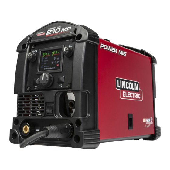
POWER MIG
Register your machine:
www.lincolnelectric.com/register
Authorized Service and Distributor Locator:
www.lincolnelectric.com/locator
Save for future reference
Date Purchased
Code: (ex: 10859)
Serial: (ex: U1060512345)
IMT10164
| Issue D ate 12/14
© Lincoln Global, Inc. All Rights Reserved.
®
210 MP
For use with machines having Code Numbers:
12185
Advertisement
Table of Contents

Related Manuals for Lincoln Electric POWER MIG 210 MP


Summary of Contents for Lincoln Electric POWER MIG 210 MP
- Page 1 Operator’s Manual POWER MIG ® 210 MP For use with machines having Code Numbers: 12185 Register your machine: www.lincolnelectric.com/register Authorized Service and Distributor Locator: www.lincolnelectric.com/locator Save for future reference Date Purchased Code: (ex: 10859) Serial: (ex: U1060512345) IMT10164 | Issue D ate 12/14 ©...
-
Page 2: Safety Depends On You
THANK YOU FOR SELECTING KEEP YOUR HEAD OUT OF THE FUMES. A QUALITY PRODUCT BY DON’T get too close to the arc. Use LINCOLN ELEC TRIC. corrective lenses if necessary to stay a reasonable distance away from the arc. READ and obey the Material Safety PLEASE EXAMINE CARTON AND EQUIPMENT FOR Data Sheet (MSDS) and the warning DAMAGE IMMEDIATELY... - Page 3 American Welding Society, P.O. Box 351040, Miami, Florida 33135 or ELECTRIC AND CSA Standard W117.2-1974. A Free copy of “Arc Welding Safety” MAGNETIC FIELDS MAY booklet E205 is available from the Lincoln Electric Company, 22801 BE DANGEROUS St. Clair Avenue, Cleveland, Ohio 44117-1199. BE SURE THAT ALL INSTALLATION, OPERATION, 2.a.
-
Page 4: Electric Shock Can Kill
SAFETY ELECTRIC SHOCK ARC RAYS CAN BURN. CAN KILL. 3.a. The electrode and work (or ground) circuits are 4.a. Use a shield with the proper filter and cover plates to protect your electrically “hot” when the welder is on. Do eyes from sparks and the rays of the arc when welding or not touch these “hot”... - Page 5 SAFETY WELDING AND CUTTING CYLINDER MAY EXPLODE IF SPARKS CAN CAUSE DAMAGED. FIRE OR EXPLOSION. 7.a. Use only compressed gas cylinders containing the correct shielding gas for the process used 6.a. Remove fire hazards from the welding area. If and properly operating regulators designed for this is not possible, cover them to prevent the welding sparks the gas and pressure used.
- Page 6 POWER MIG ® 210 MP TABLE OF CONTENTS...
-
Page 7: Product Summary
POWER MIG ® 210 MP PRODUCT DESCRIPTION PRODUCT DESCRIPTION PRODUCT SUMMARY The Power MIG™ 210 MP is a multi-process CC/CV DC inverter rated for 200 amps, 24 volts at a 25% duty cycle. The Power MIG™ units are intended for fabrication, maintenance, home, and autobody shops. -
Page 8: Recommended Processes
PRODUCT DESCRIPTION RECOMMENDED PROCESSES AND EQUIPMENT COMMON EQUIPMENT PACKAGES RECOMMENDED PROCESSES The Power MIG ® 210 MP is recommended for GMAW, FCAW, GTAW, and SMAW processes. The machine can support 4 inch and 8 inch BASIC PACKAGE: spools of wire for GMAW and FCAW welding. The machine is intended CODE 12185 DETAILS for the following wire diameters and composition;... -
Page 9: Specifications
POWER MIG ® 210 MP DESIGN DESIGN SPECIFICATIONS POWER SOURCES - INPUT VOLTAGE AND CURRENT WELDING PROCESSES PROCESS ELECTRODE DIAMETER RANGE OUTPUT RANGE WIRE FEED DUTY CYCLE INPUT VOLTAGE INPUT AMPERES IDLE AMPS (OUTPUT) (AMPERES) SPEED RANGE .55A GMAW .025-.035” 20-220 50-500 IPM (200A / 24V) -
Page 10: Regulatory Requirements
• Efficient Inverter power topology- reduces power consumption and reduces the mass of the unit when compared with traditional SCR based machines. • High Power Factor- The Power MIG 210 MP features active power factor correction (>.98) which greatly reduces the unit’s current draw. -
Page 11: Case Front Control Descriptions
POWER MIG ® 210 MP DESIGN CASE FRONT CONTROLS FIGURE A.1 CASE FRONT CONTROL DESCRIPTIONS 8. Gun Connection – Permits attachment of a MIG welding gun. 1. Storage Compartment – Provides storage for small items such as Ensure the gun is fully seated into the brass receptacle. tips and drive rolls. -
Page 12: Internal Controls
CASE REAR COMPONENTS DESCRIPTION 4. Replaceable Wire Guide – Select the correct inner wire guide for 1. Thermal Breaker – The Power MIG 210 MP features a resettable the desired wire diameter. The outer wire guide provided can be 25 amp thermal breaker. If the current conducted through the used for any wire diameter. -
Page 13: Product Model
PRODUCT MODEL NOTES... -
Page 14: Location And Mounting
210 MP INSTALLATION INSTALLATION 3. The Power MIG 210 MP is shipped with (two) six-foot power cords. 4. Using the instructions in Figure B.2, have a qualified electrician connect a receptacle (Customer Supplied) or cable to the input power lines and the system ground per the U.S. National Electrical WARNING Code and any applicable local codes. -
Page 15: Gun And Cable Installation
5. Attach one end of the inlet gas hose to the outlet fitting of the flow 4. Connect the gun trigger connector from the gun and regulator, the other end to the Power MIG 210 MP rear fitting, and cable to the mating receptacle located on the machine tighten the union nuts with a wrench. -
Page 16: Electrode And Work Connections
POWER MIG ® 210 MP INSTALLATION PROCEDURE FOR CHANGING DRIVE AND IDLE ROLL SETS ELECTRODE AND WORK CONNECTIONS 1. Turn off the power source. OUTPUT POLARITY CONNECTIONS 2. Release the pressure on the idle roll by swinging the adjustable The Power MIG 210MP features a short lead protruding from the front pressure arm down toward the back of the machine. -
Page 17: Power-Up Sequence
POWER MIG ® 210 MP OPERATION OPERATION GRAPHIC SYMBOLS USED IN THIS MANUAL OR BY THIS MACHINE POWER-UP SEQUENCE 1. Check that the electrode polarity is correct for the process being 3. Press the trigger to feed the wire electrode through the gun and used, then turn the power switch ON. - Page 18 POWER MIG ® 210 MP OPERATION The following images help indicate the machine setup process. Figure C.1 Figure C.2 Verify polarity configuration and gas mix. Then press knob to continue.
- Page 19 POWER MIG ® 210 MP OPERATION Figure C.3 Figure C.4...
- Page 20 POWER MIG ® 210 MP OPERATION Figure C.5 Figure C.6...
-
Page 21: Duty Cycle
The machine must cool down before welding can be performed. INPUT LINE VOLTAGE VARIATIONS High Line Voltage/ Low Line Voltage — The Power MIG 210 MP will operate between 100 and 250VAC 60Hz WIRE FEED OVERLOAD PROTECTION The Power MIG 210MP features overload protection of the wire drive motor. -
Page 22: Options And Settings
PRODUCT MODEL OPERATION OPTIONS AND SETTINGS MIG OPTIONS The user interface software settings can be reset to the original factory settings. The inductance option permits adjusting the arc performance, this option can be used to help with starting and the weld bead profile. - Page 23 POWER MIG ® 210 MP OPERATION...
-
Page 24: Drive Roll Kits
POWER MIG ® 210 MP ACCESSORIES GENERAL OPTIONS / ACCESSORIES DRIVE ROLL KITS WIRE SIZE DRIVE ROLL KIT .023" - .030" KP2529-1 (0.6 - 0.8 MM) SOLID .035" (0.9 MM) KP2529-2 CORED .030- .045" (0.9 MM) KP2529-3 KITS AND OPTIONS K520 UTILITY CART (150 CU FT. -
Page 25: Periodic Maintenance
POWER MIG ® 210 MP MAINTENANCE ROUTINE MAINTENANCE CAUTION PERIODIC MAINTENANCE WARNING LINER REMOVAL, INSTALLATION AND TRIMMING INSTRUCTIONS FOR MAGNUM PRO 175L NOTE: The variation in cable lengths prevents interchanging of liners Before carrying out service, maintenance and/or between guns. Once a liner has been cut for a particular gun, it repair jobs, fully disconnect power to the machine. -
Page 26: How To Use Troubleshooting Guide
HOW TO USE TROUBLESHOOTING GUIDE WARNING Service and Repair should only be performed by Lincoln Electric Factory Trained Personnel. Unauthorized repairs performed on this equipment may result in danger to the technician and machine operator and will invalidate your factory warranty. - Page 27 POWER MIG ® 210 MP TROUBLE SHOOTING Observe all Safety Guidelines detailed throughout this manual PROBLEMS POSSIBLE RECOMMENDED (SYMPTOMS) CAUSE COURSE OF ACTION Major physical or electrical damage is “Do not Plug in machine or turn it on.” evident. Contact your local Authorized Field Service Facility.
- Page 28 POWER MIG ® 210 MP TROUBLE SHOOTING Observe all Safety Guidelines detailed throughout this manual PROBLEMS POSSIBLE RECOMMENDED (SYMPTOMS) CAUSE COURSE OF ACTION Arc is unstable - Poor starting. 1. Check for correct input voltage to machine. 2. Check for proper electrode polarity for process.
- Page 29 POWER MIG ® 210 MP DIAGRAMS...
- Page 30 POWER MIG ® 210 MP DIAGRAMS...
- Page 31 POWER MIG ® 210 MP NOTES...
- Page 32 Lincoln Electric for advice or information about their use of our products. We respond to our customers based on the best information in our possession at that time. Lincoln Electric is not in a position to warrant or guarantee such advice, and assumes no liability, with respect to such information or advice.
-
Page 33: Power Mig
Manual del operador ® POWER MIG 210 MP Para utilizar con máquinas que tengan los siguientes Números de código: 12185 www.lincolnelectric.com/register Registre su máquina: www.lincolnelectric.com/locator Localizador de distribuidores y servicios autorizados: Guarde estos datos como referencia para el futuro Fecha de la compra Código: (ej.: 10859) Serie: (ej.: U1060512345) | Fecha de emisión: 12/14... - Page 34 GRACIAS POR SELECCIONAR MANTENGA LA CABEZA LEJOS DE LOS HUMOS. UN PRODUCTO DE CALIDAD DE NO se acerque demasiado al arco. LINCOLN ELECTRIC. Use lentes correctores, si fuera necesario, para permanecer a una distancia razonable del arco. LEA y obedezca lo que indique la Hoja...
- Page 35 UU.), o la norma canadiense CSA W117.2-1974. Puede obtenerse un ELÉCTRICOS Y ejemplar gratis del folleto E205, 'Seguridad en la soldadura por arco' ('Arc Welding Safety'), en Lincoln Electric Company, 22801 St. Clair MAGNÉTICOS PUEDEN Avenue, Cleveland, Ohio 44117-1199, EE. UU.
- Page 36 SEGURIDAD EL CHOQUE LOS RAYOS DE LOS ELÉCTRICO PUEDE ARCOS PUEDEN MATAR. QUEMAR. 4.a. Utilice un blindaje con las placas de cubierta y de filtro correctas a fin 3.a. Los circuitos del electrodo y la pieza de trabajo de proteger los ojos de las chispas y los rayos del arco cuando (o tierra) están eléctricamente 'vivos' cuando se enciende la suelda u observa una soldadura de arco abierto.
- Page 37 SEGURIDAD LAS CHISPAS DE EL CILINDRO PUEDE EXPLOTAR SOLDADURA PUEDEN SI SE DAÑA. PROVOCAR UN 7.a. Utilice únicamente cilindros de gas INCENDIO O UNA comprimido que contengan el gas protector correcto para el proceso utilizado y EXPLOSIÓN. reguladores en buenas condiciones de funcionamiento, diseñados para el gas y la 6.a.
- Page 38 POWER MIG ® 210 MP ÍNDICE...
-
Page 39: Resumen Del Producto
POWER MIG ® 210 MP DESCRIPCIÓN DEL PRODUCTO DESCRIPCIÓN DEL PRODUCTO RESUMEN DEL PRODUCTO ® La Power MIG 210 MP es una unidad de CD multiproceso de corriente constante/tensión constante con inversor, especificada para 200 A/24 V con un ciclo de trabajo de 25%. Las unidades Power MIG™... - Page 40 DESCRIPCIÓN DEL PRODUCTO PROCESOS Y EQUIPOS RECOMENDADOS PROCESOS RECOMENDADOS ® La Power MIG 210 MP se recomienda para los procesos GMAW, CONJUNTOS DE EQUIPO COMUNES FCAW, GTAW y SMAW. La máquina admite carretes de alambre de 4 pulgadas y de 8 pulgadas para soldadura GMAW y FCAW. La máquina está...
-
Page 41: Especificaciones
POWER MIG 210 MP DISEÑO ® DISEÑO ESPECIFICACIONES PROCESOS DE SOLDADURA FUENTES DE ENERGÍA - TENSIÓN Y CORRIENTE DE ENTRADA CICLO DE TRABAJO TENSIÓN DE CORRIENTE DE CORRIENTE DE PROCESO RANGO DE DIÁMETROS DE RANGO DE RANGO DE VELOC. (SALIDA) ENTRADA (V) ENTRADA MÁXIMOS REPOSO... -
Page 42: Características De Diseño
(SCR). • Alto factor de potencia - la Power MIG 210 MP tiene corrección activa del factor de potencia (>0.98), que reduce considerablemente el consumo de corriente de la unidad. - Page 43 POWER MIG 210 MP DISEÑO ® CONTROLES DEL FRENTE DEL GABINETE FIGURA A.1 DESCRIPCIONES DE LOS CONTROLES DEL FRENTE DEL soldadura MIG. Asegúrese de que la pistola esté completamente GABINETE asentada en el receptáculo de latón. 1. Compartimiento para almacenamiento: proporciona almacenamiento 9.
- Page 44 POSTERIOR DEL GABINETE 4. Guía de alambre reemplazable: seleccione la guía de alambre interior 1. Interruptor automático térmico: la Power MIG 210 MP cuenta con un correcta para el diámetro de alambre deseado. La guía de alambre interruptor automático térmico de 25 A con reposición. Si la corriente exterior proporcionada puede utilizarse para cualquier diámetro de...
- Page 45 POWER MIG ® 210 MP NOTAS...
-
Page 46: Ubicación Y Montaje
-------------------------------------------------------- CONEXIONES DE ENTRADA Y DE TIERRA • La Power MIG 210 MP debe ubicarse en un área con circulación de aire limpio, de modo que el aire ingrese por la parte posterior y salga 1. Antes de comenzar la instalación, verifique con la compañía de elect- por las rejillas frontales. -
Page 47: Gas Protector
Power MIG 210 MP, y apriete las tuercas de Asegúrese de que el conector esté insertado comple- unión con una llave. -
Page 48: Conexiones De Polaridad De Salida
2. Descargue la presión del rodillo intermedio; para ello haga girar el brazo de presión ajustable hacia la parte posterior de la máquina. La Power MIG 210 MP cuenta con un conductor de conexión corto que Levante el conjunto de fundición del rodillo intermedio y deje que sobresale del frente de la máquina;... - Page 49 POWER MIG ® 210 MP OPERACIÓN OPERACIÓN SÍMBOLOS GRÁFICOS UTILIZADOS EN ESTE MANUAL O POR ESTA MÁQUINA ALIMENTACIÓN ELÉCTRICA DE ENTRADA TENSIÓN DE CIRCUITO ABIERTO ENCENDIDO (ON) TENSIÓN DE ENTRADA APAGADO (OFF) TENSIÓN DE SALIDA ALTA TEMPERATURA CORRIENTE DE ENTRADA ESTADO DE LA MÁQUINA CORRIENTE DE SALIDA INTERRUPTOR AUTOMÁTICO...
- Page 50 POWER MIG ® 210 MP OPERACIÓN Las imágenes siguientes ayudan a indicar el proceso de configuración de la máquina. Figura C.1 Haga girar la perilla hasta la opción seleccionada. Oprima la perilla para seleccionar. Figura C.2 Verifique la configuración de polaridad y la mezcla de gases.
- Page 51 POWER MIG ® 210 MP OPERACIÓN Figura C.3 Haga girar la perilla hasta la opción seleccionada. Oprima la perilla para seleccionar. Figura C.4 Haga girar la perilla hasta la opción seleccionada. Oprima la perilla para seleccionar.
- Page 52 POWER MIG ® 210 MP OPERACIÓN Figura C.5 Oprima la perilla para ver el menú de opciones. Figura C.6 Haga girar la perilla hasta la opción seleccionada. Oprima la perilla para seleccionar.
-
Page 53: Ciclo De Trabajo
(tiempo 'Off') antes de soldar nuevamente. VARIACIONES DE LA TENSIÓN DE LÍNEA DE ENTRADA Tensión de línea alta / Tensión de línea baja: la Power MIG 210 MP puede operar entre 100 y 250 V CA, 60 Hz. - Page 54 Una fuerza del arco alta crea un arco vigoroso, mientras que una fuerza del arco baja crea un arco suave. La La Power MIG 210 MP está preparada para funcionar con la pistola opción de fuerza del arco está disponible en el modo SMAW.
- Page 55 POWER MIG ® 210 MP OPERACIÓN...
-
Page 56: Kits De Rodillos Impulsores
POWER MIG ® 210 MP ACCESORIOS OPCIONES GENERALES / ACCESORIOS KITS DE RODILLOS IMPULSORES ALAMBRE TAMAÑO KIT DE RODILLOS IMPULSORES .023" - .030" KP2529-1 (0.6 - 0.8 MM) SÓLIDO .035" (0.9 MM) KP2529-2 TUBULAR .030- .045" (1.2 MM) KP2529-3 KITS Y OPCIONES KITS OPCIONALES NÚMERO TIPO... -
Page 57: Mantenimiento Periódico
POWER MIG ® 210 MP MANTENIMIENTO MANTENIMIENTO DE PRECAUCIÓN RUTINA MANTENIMIENTO PERIÓDICO INSTRUCCIONES DE EXTRACCIÓN DEL REVESTIMIENTO, INSTALACIÓN Y ADVERTENCIA CORTE A MEDIDA PARA LA MAGNUM PRO 175L NOTA: la variación de las longitudes de cable impide el intercambio de reves- timientos entre pistolas. - Page 58 El servicio y las reparaciones deben estar únicamente a cargo de personal capacitado en la fábrica de Lincoln Electric. Las reparaciones no autorizadas realizadas en este equipo pueden resultar peligrosas para el técnico y para el operador de la máquina, e invalidarán su garantía de fábrica.
-
Page 59: Localización De Fallas
POWER MIG ® 210 MP LOCALIZACIÓN DE FALLAS Observe todas las pautas de seguridad que se detallan en este manual. PROBLEMA CAUSA CURSO DE ACCIÓN (SÍNTOMA) POSIBLE RECOMENDADO Hay un daño físico o eléctrico importante *No enchufe la máquina ni la encienda*. y evidente. - Page 60 POWER MIG ® 210 MP LOCALIZACIÓN DE FALLAS Observe todas las pautas de seguridad que se detallan en este manual. PROBLEMA CAUSA CURSO DE ACCIÓN (SÍNTOMA) POSIBLE RECOMENDADO 1. Verifique que la tensión de entra El arco es inestable. El arranque es da a la máquina sea correcta.
- Page 61 POWER MIG ® 210 MP DIAGRAMAS...
- Page 62 POWER MIG ® 210 MP DIAGRAMAS...
- Page 63 POWER MIG ® 210 MP NOTAS...
- Page 64 POLÍTICA DE ASISTENCIA AL CLIENTE El negocio de The Lincoln Electric Company es la fabricación y venta de equipos de soldadura, consumibles y equipos de corte de alta calidad. Nuestro desafío es satisfacer las necesidades de nuestros clientes y superar sus expectativas. En ocasiones, los compradores pueden pedir a Lincoln Electric consejo o información acerca de su uso de los productos.
- Page 65 Manuel de l’opérateur POWER MIG ® 210 MP Pour une utilisation avec des machines ayant des numéros de code : 12185 www.lincolnelectric.com/register Enregistrez votre machine : www.lincolnelectric.com/locator Localisateur de partenaires agréés de service et distribution : À conserver comme référence ultérieure Date de l’achat Code : (par ex : 10859) N°...
- Page 66 MERCI D’AVOIR CHOISI GARDEZ VOTRE TÊTE HORS DES FUMÉES. UN PRODUIT DE QUALITÉ NE vous approchez PAS trop près de DE LINCOLN ELECTRIC. l’arc. Utilisez s’il le faut des verres correcteurs pour pouvoir rester à une distance raisonnable de l’arc.
- Page 67 Florida 33135, USA) ou de la norme CSA W117.2-1974. Une copie gratuite du fascicule E205 sur la sécurité en soudage à l’arc, “Arc Welding Safety”, est 2.a. Un courant électrique circulant au travers de disponible chez Lincoln Electric Company (22801St. Clair Avenue, Cleveland, n’importe quel conducteur cause des champs Ohio 44117-1199, USA).
- Page 68 SÉCURITÉ UNE COMMOTION LES RAYONS D’ARC ÉLECTRIQUE PEUT PEUVENT CAUSER DES ÊTRE MORTELLE. BRÛLURES. 3.a. Les circuits d’électrode et de retour (masse) sont 4.a. Utilisez un écran avec le bon filtre et des éléments protecteurs pour électriquement sous tension quand la machine à souder est activée. Ne protéger vos yeux des étincelles et des rayons de l’arc quand vous soudez touchez pas ces parties sous tension avec votre peau nue ou des ou observez un soudage à...
- Page 69 SÉCURITÉ DES ÉTINCELLES DE UNE BOUTEILLE DE GAZ SOUDAGE OU DE ENDOMMAGÉE PEUT EXPLOSER. DÉCOUPAGE PEUVENT 7.a. N’utilisez que des bouteilles de gaz sous pression CAUSER UN DÉPART contenant le gaz de protection correct pour le processus utilisé, et des régulateurs en bon état de D’INCENDIE OU UNE marche conçus pour le type de gaz et la pression EXPLOSION.
- Page 70 POWER MIG ® 210 MP TABLE DES MATIÈRES...
-
Page 71: Présentation Du Produit
DESCRIPTION DU PRODUIT POWER MIG ® 210 MP DESCRIPTION DU PRODUIT PRÉSENTATION DU PRODUIT Le Power MIG™ 210 MP est un convertisseur continu multiprocessus à courant constant/tension constante, spécifié pour 200 ampères, 24 volts à cycle de travail de 25 %. Les appareils Power MIG™ sont prévus pour la fabrication, l’entretien, la maison et les ateliers automobiles. - Page 72 DESCRIPTION DU PRODUIT PROCESSUS ET ÉQUIPEMENT RECOMMANDÉS PROCESSUS RECOMMANDÉS ENSEMBLES D’ÉQUIPEMENT COURANTS Le Power MIG ® 210 MP est recommandé pour les processus GMAW, FCAW, ENSEMBLE DE GTAW, et SMAW. Le poste peut supporter des bobines de 4 et 8 pouces pour BASE : CODE 12185 DÉTAILS du soudage type GMAW et FCAW.
-
Page 73: Spécifications
POWER MIG ® 210 MP CONCEPTION CONCEPTION SPÉCIFICATIONS SOURCES SECTEUR – PROCESSUS DE SOUDAGE TENSION ET COURANT D’ENTRÉE CYCLE DE TRAVAIL TENSION AMPÈRES AMPÈRES AU PROCESSUS PLAGE DE DIAMÈTRE COURANT DE PLAGE DE VITESSE (SORTIE) D’ENTRÉE D’ENTRÉE MAX RALENTI D’ALIMENTATION SORTIE (AMPÈRES) D’ÉLECTRODE DE FIL... - Page 74 énergétique et de la masse du poste en comparaison avec des machines traditionnelles avec alimentation à thyristors (SCR). • Facteur de forme élevé - Le Power MIG 210 MP comporte une correction active de facteur de forme (>0,98) qui diminue notablement le courant consommé...
- Page 75 POWER MIG ® 210 MP CONCEPTION CONTRÔLES DE CARTER AVANT FIGURE A.1 DESCRIPTIONS DES COMMANDES À L’AVANT DU CARTER 1. Compartiment de rangement – Offre de la place pour des petits articles 8. Connexion de pistolet – Permet de brancher un pistolet de soudage pour MIG. comme des embouts et des rouleaux de dévidoir.
- Page 76 DESCRIPTION DES COMPOSANTS À L’ARRIÈRE DU CARTER 4. Guide-fil remplaçable – Sélectionne le guide-fil intérieur correct pour le 1. Disjoncteur thermique – Le Power MIG 210 MP comporte un disjoncteur diamètre de fil voulu. Le guide-fil extérieur fourni peut servir pour thermique de 25 amères réactivable après son déclenchement.
- Page 77 POWER MIG® 210 MP NOTES...
- Page 78 210 MP INSTALLATION INSTALLATION 3. Le Power MIG 210 MP est livré avec deux cordons d’alimentation de six pieds (1,8 m). 4. En utilisant les instructions de la Figure B.2, confiez à un électricien qualifié la connexion sur une prise (fourniture locale) ou le câblage sur les AVERTISSEMENT conduites de secteur et la mise à...
- Page 79 à l’arrière du procédé de soudage utilisé. Power MIG 210 MP, et serrez les raccords union avec une clé. Un régulateur du flux de gaz, pour mélange gazeux d’argon, et un tuyau 6.
- Page 80 POWER MIG ® 210 MP INSTALLATION PROCÉDURE POUR CHANGER LES JEUX DE ROULEAUX D’ENTRAÎNEMENT CONNEXIONS D’ÉLECTRODE ET DE PIÈCE ET DE TENSION 1. Coupez la source d’alimentation secteur. CONNEXIONS DE POLARITÉ DE SORTIE Le Power MIG 210MP comporte un court cordon sortant de son avant, il peut 2.
-
Page 81: Séquence De Démarrage
POWER MIG ® 210 MP FONCTIONNEMENT FONCTIONNEMENT SYMBOLES GRAPHIQUES UTILISÉS DANS CE MANUEL OU SUR CE POSTE DE SOUDAGE TENSION D’ENTRÉE TENSION DE CIRCUIT DE SORTIE MARCHE TENSION D’ENTRÉE ARRÊT TENSION DE SORTIE TEMPÉRATURE ÉLEVÉE STATUT DU POSTE COURANT D’ENTRÉE DISJONCTEUR COURANT DE SORTIE ALIMENTATION EN FIL... - Page 82 POWER MIG ® 210 MP FONCTIONNEMENT Les images qui suivent indiquent le processus de mise en œuvre du poste. Figure C.1 Figure C.2 Verify polarity configuration and gas mix. Then press knob to continue.
- Page 83 POWER MIG ® 210 MP FONCTIONNEMENT Figure C.3 Figure C.4...
- Page 84 POWER MIG ® 210 MP FONCTIONNEMENT Figure C.5 Figure C.6...
- Page 85 La machine doit refroidir avant de soudage peut être effectué. VARIATIONS DE TENSION DU SECTEUR D’ENTRÉE Tension secteur haute et basse – Le Power MIG 210 MP fonctionnera s’il est alimenté entre 100 et 250 V CA/60 Hz. PROTECTION CONTRE LA SURCHARGE D’ALIMENTATION EN FIL Le Power MIG 210MP comporte une protection contre la surcharge du moteur d’entraînement du fil.
- Page 86 POWER MIG® 210 MP FONCTIONNEMENT OPTIONS ET RÉGLAGES OPTIONS MIG MIG OPTIONS Les paramètres d’interface utilisateur peuvent être restaurés aux The user interface software settings can be reset to the original valeurs d’usine d’origine. factory settings. The inductance option permits adjusting the arc performance, L’option d’inductance permet de régler la performance de l’arc, this option can be used to help with starting and the weld bead elle peut s’utiliser pour aider au démarrage et pour le profil du...
- Page 87 POWER MIG ® 210 MP FONCTIONNEMENT...
- Page 88 POWER MIG ® 210 MP ACCESSORIES OPTION GÉNÉRALES / ACCESSOIRES KITS DE DÉVIDOIR DE FIL TAILLE KIT DE DÉVIDOIR DE FIL ,023" – 0,030" KP2529-1 (0,6 – 0,8 MM) PLEIN 0,035" (0,9 MM KP2529-2 AVEC ÂME 0,030- 0,045" KP2529-3 (0,8 - 11,4 MM) KITS ET OPTIONS KITS OPTIONNELS RÉF.
-
Page 89: Maintenance Périodique
POWER MIG ® 210 MP MAINTENANCE MAINTENANCE DE ROUTINE AVERTISSEMENT ATTENTION MAINTENANCE PÉRIODIQUE DÉPOSE DE LA GAINE, INSTALLATION ET INSTRUCTIONS DE MISE EN Avant de lancer une intervention de service, ROUTE POUR MAGNUM PRO 175L maintenance et/ou de réparation, débranchez REMARQUE : La variation des longueurs de câble empêche d’échanger des complètement l’alimentation électrique vers le gaines entre pistolets. -
Page 90: Dépannage
Les interventions de service et de réparation ne doivent être menées que par du personnel formé par l’usine de Lincoln Electric. Des réparations non autorisées faites sur cet équipement peuvent entraîner un danger pour le technicien et l’opérateur du poste de soudage, et annulent sa garantie. - Page 91 POWER MIG ® 210 MP DÉPANNAGE PROBLÈMES CAUSE ACTION CURATIVE Prenez en compte toutes les informations de sécurité de ce manuel. (SYMPTÔMES) POSSIBLE RECOMMANDÉE Dommage physique ou électrique évident "Ne branchez pas électriquement le poste de soudage et ne le mettez pas en marche." Contactez votre centre de service local agréé.
- Page 92 POWER MIG ® 210 MP DÉPANNAGE Prenez en compte toutes les informations de sécurité de ce manuel. PROBLÈMES CAUSE ACTION CURATIVE (SYMPTÔMES) POSSIBLE RECOMMANDÉE L’arc est instable Le démarrage est 1. Contrôlez que la tension secteur arrivant médiocre au poste de soudage est correcte. 2.
- Page 93 POWER MIG ® 210 MP SCHÉMAS...
- Page 94 POWER MIG ® 210 MP SCHÉMAS...
- Page 95 POWER MIG ® 210 MP NOTES...
- Page 96 We respond to our customers based on the best information meilleures informations dont nous disposons à ce moment là. Lincoln Electric in our possession at that time. Lincoln Electric is not in a position to n’est pas en position pour garantir de tels conseils, et n’assume aucune warrant or guarantee such advice, and assumes no liability, with responsabilité...