
Related Manuals for Chamberlain TAC11


Summary of Contents for Chamberlain TAC11
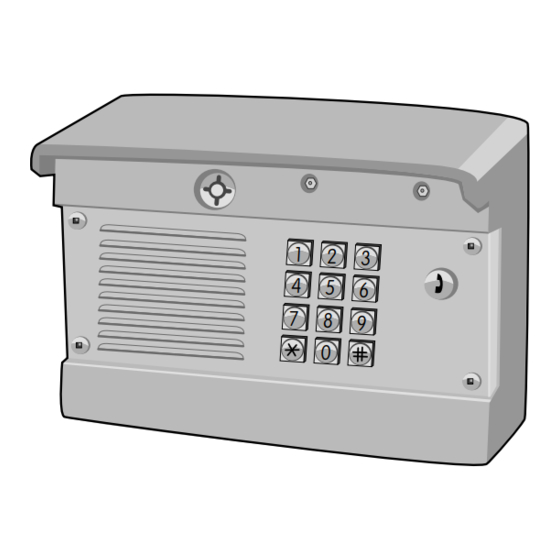
- Page 1 TAC1 Telephone Entry System Installation and Programming Manual The Chamberlain Group 845 Larch Ave. Elmhurst, IL 60126-1196 www.liftmaster.com...
-
Page 2: Table Of Contents
Code Setup and Code Operation Description of the Processor Board From the Telephone 15-16 Overview of Telco Wiring Program a Pre-Installed Liftmaster Receiver Wiring the Unit With a Telco Line Quick Reference 17-18 Wiring the Unit Without a Telco Line... -
Page 3: Specifications
SPECIFICATIONS >> CABLE REQUIREMENTS, DIMENSIONS AND CARTON INVENTORY CABLE REQUIREMENTS Outdoor installations require shielded cable. Non-shielded cable can be used for indoor installations ONLY. PROCESSOR BOARD WIRE TYPE RECOMMENDATIONS From the power transformer at 120 Vac outlet 2 - Conductor Cable Shielded Only - See Power Wire Table Below From the door strike, maglock or gate operator 2 - Conductor Cable... -
Page 4: Installation
INSTALLATION >> MOUNT THE BACK PANEL AND OVERVIEW OF THE PROCESSOR BOARD MOUNT THE BACK PANEL Choose the mounting location for the unit. Remove the back panel and attach the unit to a solid surface or post (hardware not provided). DESCRIPTION OF THE PROCESSOR BOARD RING RING... -
Page 5: Overview Of Telco Wiring
INSTALLATION >> OVERVIEW OF TELCO WIRING Many phone companies have updated their color standards due to Notes about wire connectors the use of Cat 5 cable for most phone line installs, and keep (terminal blocks): residential and business installs in line with each other. In the new •... -
Page 6: Wiring The Unit With A Telco Line
INSTALLATION >> WIRING THE UNIT WITH A TELCO LINE AND WIRING THE UNIT WITHOUT A TELCO LINE Never run data wires and high voltage wires in the same conduit. The high voltage wires may interfere with the data wires and cause the system to malfunction. WIRING THE UNIT WITH A TELCO LINE Ringer Equivalence Number (REN) = 5 RING... -
Page 7: Wiring A Gate Operator
INSTALLATION >> WIRING A GATE OPERATOR (NORMALLY OPEN) AND WIRING AN AUTO-CALL SENSOR WIRING A GATE OPERATOR (NORMALLY OPEN) The gate operator can be connected to Relay 1 or Relay 2. See the Notes about wire connectors Programming section for information about configuring Relays 1 (terminal blocks): and 2. -
Page 8: Wiring A Gate Operator And A Door Strike Lock
INSTALLATION >> WIRING A GATE OPERATOR (NORMALLY OPEN) A DOOR STRIKE LOCK (NORMALLY OPEN) AND WIRING A GATE OPERATOR (NORMALLY OPEN) & A MAGLOCK (NORMALLY CLOSED) WIRING A GATE OPERATOR (NORMALLY OPEN) & A DOOR STRIKE LOCK (NORMALLY OPEN) The door strike can be connected to Relay 1 or Relay 2. See the Notes about wire connectors Programming section for information about configuring Relays 1 (terminal blocks):... -
Page 9: Wiring A Door Strike Lock
INSTALLATION >> WIRING A DOOR STRIKE LOCK (NORMALLY OPEN) AND WIRING A MAGLOCK (NORMALLY CLOSED) WIRING A DOOR STRIKE LOCK (NORMALLY OPEN) The door strike can be connected to Relay 1 or Relay 2. See the Notes about wire connectors Programming section for information about configuring Relays 1 (terminal blocks): and 2. -
Page 10: Earth Ground Rod
INSTALLATION >> EARTH GROUND ROD AND POWER WIRING EARTH GROUND ROD Ensure that the unit is grounded properly. The unit contains a To AVOID damaging gas, power or other underground utility number of static sensitive components that can be damaged by lines, contact underground utility locating companies BEFORE static discharge. -
Page 11: Plug The Transformer Into The Outlet
INSTALLATION >> PLUG THE TRANSFORMER INTO THE OUTLET, MOUNT THE UNIT AND SET THE UNIT MASTER CODE PLUG THE TRANSFORMER INTO THE OUTLET Plug the transformer into the 110 Vac outlet. 12 Vac Power (included) POWER 110 Vac Outlet Check the Power LED is illuminated. -
Page 12: Testing
TESTING >> TEST THE GATE/DOOR RELAYS AND TEST THE TELEPHONE CONNECTIONS TEST GATE/DOOR RELAYS TEST RELAY 1 Enter 4 digit Master Code + 1 (Key). The “1” Key indicates the Relay to be triggered. NOTE: Relay 1 status indicator LED will illuminate (Blue) to show activity when triggered. -
Page 13: Programming
PROGRAMMING >> FROM THE TAC1 KEYPAD GENERAL INSTRUCTION NOTE: Use the STAR Key “*” to cancel any input. PROGRAMMING INSTRUCTION SYNTAX KEYSTROKES General Programming Master Code + Command 1234 + 1 (12,123) Code Programming Master Code + Command + Code 1234 +1(12) + 1234 Relay Programming Master Code + Command + Setting... -
Page 14: Code Setup And Code Operation
PROGRAMMING >> CODE SETUP AND CODE OPERATION CODE SETUP The unit’s Master Code is for owner/administrator level commands. The User Codes allow users to activate and latch relays 1 and 2 and to transmit radio commands on channels one and two. NOTE: The User Code cannot be the same as the Master Code. -
Page 15: From The Telephone
PROGRAMMING >> FROM THE TELEPHONE TELEPHONE PROGRAMMING ENABLE INTERCOM MODE ADJUST “PICK UP” RING COUNT Enter the command tone: 1. Enter the command tone: 2. Enter the ring count: through ENABLE TELCO MODE Enter the command tone: ENABLE ALTERNATE DTMF PROGRAMMING This feature changes the first programming digit from ENABLE STANDARD (LONG) RING TONE Enter the command tone:... -
Page 16: Program A Pre-Installed Liftmaster Receiver
NOTE: An error tone will be heard for 3 consecutive activations only. After the third activation the unit assumes that the unit has been replaced with the receiver. Repeat steps 2-4 for each LiftMaster door or gate operator that will be controlled (2 maximum). ERASE ALL CONTROL CODES... -
Page 17: Quick Reference
PROGRAMMING >> QUICK REFERENCE KEYPAD PROGRAMMING PROGRAMMING DESCRIPTION OF TASK FACTORY PROGRAMMING PROCEDURE NUMBER SETTING Trigger Relay One and Radio Master Code (4 digits) + 1 Channel One Trigger Relay Two and Radio Master Code (4 digits) + 2 Channel Two Delete User Code Master Code (4 digits) + 7 + User Code that is to be deleted (4 digits) -
Page 18: Quick Reference
PROGRAMMING >> QUICK REFERENCE TELEPHONE PROGRAMMING PROGRAMMING DESCRIPTION OF TASK FACTORY PROGRAMMING PROCEDURE NUMBER SETTING **01 Enable Call Forwarding Disabled **01 **02 Disable Call Forwarding **02 **03 Enable Intercom Mode Disabled **03 **06 Verify Call Forwarding Number Disabled **06 (Via Caller ID) **07 Enable Telco Mode Disabled... -
Page 19: Tac1 Master Code
TAC1 MASTER CODE Write down the Master Code and store in a secure location. -
Page 20: Limited Warranty
FOR TECHNICAL SUPPORT DIAL OUR TOLL FREE NUMBER: 1-800-528-2806 www.liftmaster.com NOTICE: To comply with FCC and or Industry Canada rules (IC), adjustment or modifications of this receiver and/or transmitter are prohibited, except for changing the code setting or replacing the battery. THERE ARE NO OTHER USER SERVICEABLE PARTS.