ProForm PRO 2000 User Manual
Pftl13113.0
Hide thumbs
Also See for PRO 2000:
- User manual (36 pages) ,
- User manual (40 pages) ,
- User manual (44 pages)
Table of Contents
Advertisement
www.proform.com
Model No. PFTL13113.0
Serial No.
Write the serial number in the space
above for reference.
Serial Number
Decal
ACTIVATE YOUR
WARRANTY
To register your product and
activate your warranty today,
go to www.proformservice.com/
registration.
CUSTOMER CARE
For service at any time, go to
www.proformservice.com.
Or call 1-888-533-1333
Mon.–Fri. 6 a.m.–6 p.m. MT
Sat. 8 a.m.–12 p.m. MT
Please do not contact the store.
CAUTION
Read all precautions and instruc-
tions in this manual before using
this equipment. Save this manual
for future reference.
USER'S MANUAL
Advertisement
Table of Contents

Related Manuals for ProForm PRO 2000


Summary of Contents for ProForm PRO 2000
- Page 1 Model No. PFTL13113.0 Serial No. USER’S MANUAL Write the serial number in the space above for reference. Serial Number Decal ACTIVATE YOUR WARRANTY To register your product and activate your warranty today, go to www.proformservice.com/ registration. CUSTOMER CARE For service at any time, go to www.proformservice.com.
-
Page 2: Table Of Contents
Apply the decal in the location shown. Note: The decals may not be shown at actual size. 305284 PROFORM is a registered trademark of ICON IP, Inc. -
Page 3: Important Precautions
4. The treadmill is intended for home use only. PROFORM dealer, call the telephone number Do not use the treadmill in any commercial, on the front cover of this manual, or see your rental, or institutional setting. - Page 4 20. The heart rate monitor is not a medical 24. Do not change the incline of the treadmill by device. Various factors, including the user’s placing objects under the treadmill. movement, may affect the accuracy of heart rate readings. The heart rate monitor is 25.
- Page 6 STANDARD SERVICE PLANS...
-
Page 7: Before You Begin
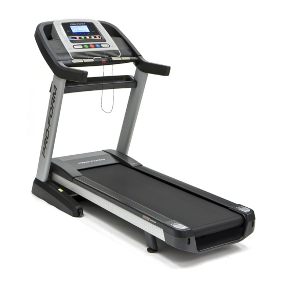
Thank you for selecting the revolutionary PROFORM ing this manual, please see the front cover of this ® PRO 2000 treadmill. The PRO 2000 treadmill offers an manual. To help us assist you, please note the product impressive selection of features designed to make your model number and serial number before contacting us. -
Page 8: Part Identification Chart
PART IDENTIFICATION CHART Use the drawings below to identify small parts used for assembly. The number in parentheses below each draw- ing is the key number of the part, from the PART LIST near the end of this manual. The number following the key number is the quantity used for assembly. -
Page 9: Assembly
ASSEMBLY • Assembly requires two persons. • To identify small parts, see page 8. • Place all parts in a cleared area and remove the • Assembly requires the following tools: packing materials. Do not dispose of the packing materials until you finish all assembly steps. the included hex key •... - Page 10 3. Identify the Left and Right Upright Covers (89, 90). Slide the Left Upright Cover (89) onto the left Upright (84), and slide the Right Upright Cover (90) onto the right Upright. Then, press the Upright Covers downward until they snap into place.
- Page 11 5. Set the console assembly (B) face down on a soft surface to avoid scratching the console assembly. Remove and discard the four indicated screws (C). Then, remove the Pulse Crossbar (80). 6. IMPORTANT: To avoid damaging the Pulse Crossbar (80), do not use power tools, and do not overtighten the #10 x 3/4"...
- Page 12 7. With the help of a second person, hold the con- sole assembly (B) near the Handrails (74). See the inset drawing. Connect the Upright Wire (83) to the console wire (D). The connec- tors should slide together easily and snap into place.
- Page 13 9. Identify the #8 x 3/4" Screws (5). IMPORTANT: Do not confuse the #8 x 3/4" Screws with the #8 x 3/4" Truss Head Screws (24). The Truss Head Screws have larger, flatter heads. Start four #8 x 3/4" Screws (5) into the Pulse Crossbar (80), and then tighten them.
- Page 14 11. Remove and discard the four indicated screws (E). Remove the Tray (97) from the Upright Crossbar (76). 12. Carefully slide the Upright Crossbar (76) between the Uprights (84). Attach the Upright Crossbar with four 5/16" x 3/4" Screws (1). Start all four Screws, and then tighten them.
- Page 15 14. Raise the Frame (52) to the position shown. Have a second person hold the Frame until step 15 is completed. Orient the Storage Latch (56) so that the decal is facing away from the treadmill as shown. Attach the lower end of the Storage Latch (56) to the bracket on the Upright (84) with a 5/16"...
-
Page 16: The Chest Heart Rate Monitor
THE CHEST HEART RATE MONITOR HOW TO PUT ON THE HEART RATE MONITOR • Do not expose the heart rate monitor to direct sun- light for extended periods of time; do not expose it to The heart rate temperatures above 122° F (50° C) or below 14° F monitor consists of (-10°... -
Page 17: How To Use The Treadmill
HOW TO USE THE TREADMILL HOW TO CONNECT THE POWER CORD nominal 120-volt circuit capable of carrying 15 or more amps. To avoid overloading the circuit, do Use a Surge Suppressor not plug other electrical devices, except for low- power devices such as cell phone chargers, into Your treadmill, like other electronic equipment, can be the surge suppressor or into an outlet on the same circuit. - Page 18 CONSOLE DIAGRAM FEATURES OF THE CONSOLE You can even listen to your favorite workout music or audio books with the console’s sound system while you The treadmill console offers an impressive array of exercise. features designed to make your workouts more effec- To turn on the power, see page 19.
-
Page 19: To Turn On The Power
HOW TO TURN ON THE POWER HOW TO USE THE MANUAL MODE IMPORTANT: If the treadmill has been exposed to 1. Insert the key into the console. cold temperatures, allow it to warm to room tem- perature before you turn on the power. If you do See HOW TO TURN ON THE POWER at the left. - Page 20 5. Follow your progress with the displays. As you exercise, the workout intensity level bar will indicate the approximate intensity level of your As you walk or run on the treadmill, the display can exercise. show the following workout information: •...
-
Page 21: To Use An Onboard Workout
7. Turn on the fan if desired. HOW TO USE AN ONBOARD WORKOUT The fan features multiple speed 1. Insert the key into the console. settings. See HOW TO TURN ON THE POWER on page 19. Press the fan buttons repeatedly to select a fan speed or to turn 2. -
Page 22: To Use A Set-A-Goal Workout
HOW TO USE A SET-A-GOAL WORKOUT The workout will continue in this way until the last segment of the profile flashes in the display and the last segment ends. The walking belt will then slow 1. Insert the key into the console. to a stop. -
Page 23: To Use An Ifit Workout
HOW TO USE AN IFIT WORKOUT For more information about the iFit workouts, please see www.iFit.com. Note: To use an iFit workout, you must have an optional iFit module. To purchase an iFit module at When you select an iFit workout, the display will any time, go to www.iFit.com or call the telephone show the name, duration, maximum speed setting, number on the front cover of this manual. - Page 24 7. Measure your heart rate if desired. THE SETTINGS MODE See step 6 on page 20. The console features a settings mode that keeps track of treadmill information and allows you to personalize 8. Turn on the fan if desired. console settings.
- Page 25 DEMO—The console features a display demo DEFAULT MENU—The default menu will appear mode, designed to be used if the treadmill is dis- when you insert the key into the console or when played in a store. While the demo mode is turned you press the Home button.
-
Page 26: How To Fold And Move The Treadmill
HOW TO FOLD AND MOVE THE TREADMILL HOW TO FOLD THE TREADMILL HOW TO MOVE THE TREADMILL To avoid damaging the treadmill, adjust the incline Before moving the treadmill, fold it as described at the to zero before you fold the treadmill. Then, remove left. -
Page 27: Maintenance And Troubleshooting
MAINTENANCE AND TROUBLESHOOTING MAINTENANCE SYMPTOM: The power turns off during use Regularly clean the treadmill and keep the walking a. Check the power switch (see drawing c at the left). belt clean and dry. First, press the power switch into If the switch has tripped, wait for five minutes and the off position and unplug the power cord. - Page 28 Locate the Reed Switch (47) and the Magnet (45) c. Your treadmill features a walking belt coated with on the left side of the Pulley (51). Turn the Pulley high-performance lubricant. IMPORTANT: Never until the Magnet is aligned with the Reed Switch. apply silicone spray or other substances to Make sure that the gap between the Magnet and the walking belt or the walking platform unless...
- Page 29 b. If the walking belt slips when walked on, first SYMPTOM: The incline of the treadmill does not remove the key and UNPLUG THE POWER change correctly CORD. Using the hex key, turn both idler roller screws clockwise, 1/4 of a turn. When the walk- a.
-
Page 30: Exercise Guidelines
EXERCISE GUIDELINES Burning Fat—To burn fat effectively, you must exer- WARNING: cise at a low intensity level for a sustained period of Before beginning this time. During the first few minutes of exercise, your or any exercise program, consult your physi- body uses carbohydrate calories for energy. -
Page 31: Part List
PART LIST Model No. PFTL13113.0 R0314A Key No. Qty. Description Key No. Qty. Description 5/16" x 3/4" Screw 5/16" x 2" Screw Drive Motor 5/16" x 1 3/4" Bolt Motor Belt 5/16" x 2 1/4" Bolt Storage Latch #8 x 3/4" Screw Right Frame Cover #10 x 3/4"... -
Page 32: Exploded Drawing
EXPLODED DRAWING A Model No. PFTL13113.0 R0314A... - Page 33 EXPLODED DRAWING B Model No. PFTL13113.0 R0314A...
- Page 34 EXPLODED DRAWING C Model No. PFTL13113.0 R0314A...
- Page 35 EXPLODED DRAWING D Model No. PFTL13113.0 R0314A...
-
Page 36: Ordering Replacement Parts
ORDERING REPLACEMENT PARTS To order replacement parts, please see the front cover of this manual. To help us assist you, be prepared to provide the following information when contacting us: • the model number and serial number of the product (see the front cover of this manual) •...