Table of Contents
Advertisement
Advertisement
Table of Contents

Related Manuals for Asus M3A78-CM


Summary of Contents for Asus M3A78-CM
- Page 1 M3A78-CM...
- Page 2 Product warranty or service will not be extended if: (1) the product is repaired, modified or altered, unless such repair, modification of alteration is authorized in writing by ASUS; or (2) the serial number of the product is defaced or missing.
-
Page 3: Table Of Contents
Contents Notices ......................vi Safety information ..................vii About this guide ..................vii M3A78-CM specifications summary ............ix Chapter 1: Product introduction Welcome! ..................1-1 Package contents ................. 1-1 Special features ................1-1 1.3.1 Product highlights ............1-1 1.3.2 Innovative ASUS features ..........1-3 Before you proceed .............. - Page 4 2.1.1 Creating a bootable floppy disk ........2-1 2.1.2 ASUS Update utility ............2-2 2.1.3 ASUS EZ Flash 2 utility ........... 2-3 2.1.4 AFUDOS utility ..............2-4 2.1.5 ASUS CrashFree BIOS 3 utility ........2-5 BIOS setup program ..............2-6 2.2.1...
- Page 5 Boot menu .................. 2-19 2.6.1 Boot Device Priority ............2-19 2.6.2 Boot Settings Configuration .......... 2-19 2.6.3 Security ................. 2-20 Tools menu ................. 2-22 2.7.1 ASUS EZ Flash 2 ............2-22 2.7.2 Express Gate [Enabled] ..........2-22 Exit menu ..................2-23...
-
Page 6: Notices
Notices Federal Communications Commission Statement This device complies with Part 15 of the FCC Rules. Operation is subject to the following two conditions: • This device may not cause harmful interference, and • This device must accept any interference received including interference that may cause undesired operation. -
Page 7: Safety Information
Safety information Electrical safety • To prevent electrical shock hazard, disconnect the power cable from the electrical outlet before relocating the system. • When adding or removing devices to or from the system, ensure that the power cables for the devices are unplugged before the signal cables are connected. If possible, disconnect all power cables from the existing system before you add a device. -
Page 8: Conventions Used In This Guide
Refer to the following sources for additional information and for product and software updates. ASUS websites The ASUS website provides updated information on ASUS hardware and software products. Refer to the ASUS contact information. Optional documentation Your product package may include optional documentation, such as warranty flyers, that may have been added by your dealer. -
Page 9: M3A78-Cm Specifications Summary
When four DDR2 1066 DIMMs are installed, all DIMMs run at 800MHz frequency by default for system stability. ** Refer to www.asus.com or user manual for Memory QVL (Qualified Vendors List) *** Due to the memory address limitation on 32-bit Windows OS,... - Page 10 Express Gate ASUS Overclocking SFS (Stepless Frequency Selection) from 200MHz to 400MHz features at 1MHz increment Adjustable DRAM voltage ASUS CPR (CPU Parameter Recall) BIOS 8Mb Flash ROM, AMI BIOS, PnP, DMI2.0, WfM2.0, ACPI2.0, SMBIOS 2.5 Accessories User manual 1 x Serial ATA signal cable...
-
Page 11: Chapter 1: Product Introduction
® The motherboard delivers a host of new features and latest technologies, making it another standout in the long line of ASUS quality motherboards! Before you start installing the motherboard, and hardware devices on it, check the items in your package with the list below. - Page 12 This enhances system performance in 3D graphics and other memory demanding applications. • DDR2 1066 is supported by AM2+ CPU only. Refer to the ASUS website at www.asus.com for the supported CPU models. • Due to AM2+ CPU limitation, only one DDR2 1066 DIMM is supported per channel.
-
Page 13: Dvi Interface
Turn your favorite photos into 256-color boot logos to personalize your system. ASUS CrashFree BIOS 3 ASUS CrashFree BIOS 3 is an auto-recovery tool that allows you to restore a corrupted BIOS file using the bundled support DVD, floppy disk, or USB disk that contains the BIOS file. -
Page 14: Asus Express Gate
ASUS EZ Flash 2 ASUS EZ Flash 2 is a utility that allows you to update the BIOS without using a bootable floppy disk or a DOS-based utility. ASUS Q-Fan ASUS Q-Fan technology intelligently adjusts CPU fan speeds according to system loading to ensure quiet, cool, and efficient operation. -
Page 15: Before You Proceed
Before you proceed Take note of the following precautions before you install motherboard components or change any motherboard settings. • Unplug the power cord from the wall socket before touching any component. • Before handling components, use a grounded wrist strap or touch a safely grounded object or a metal object, such as the power supply case, to avoid damaging them due to static electricity. -
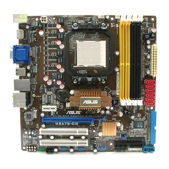
Page 16: Motherboard Overview
Screw holes Place eight screws into the holes indicated by circles to secure the motherboard to the chassis. Do not overtighten the screws! Doing so can damage the motherboard. Place this side towards the rear of the chassis. ASUS M3A78-CM... -
Page 17: Motherboard Layout
1.5.3 Motherboard layout 1.5.4 Layout contents Connectors/Jumpers/Slots Page Connectors/Jumpers/Slots Page ATX power connectors 1-21 10. Serial port connector (10-1 pin COM1) 1-21 (24-pin EATXPWR, 4-pin ATX12V) AM2/AM2+ CPU socket System panel connector (20-8 pin PANEL) 1-23 CPU fan connector (4-pin CPU_FAN) 12. -
Page 18: Central Processing Unit (Cpu)
Press the lever sideways to unlock the socket, then lift it up to a 90°- Socket lever 100° angle. Ensure that the socket lever is lifted up to 90°-100° angle, otherwise the CPU will not fit in completely. ASUS M3A78-CM... - Page 19 Position the CPU above the socket such that the CPU corner with the gold triangle matches the socket corner with a small triangle. Carefully insert the CPU into the socket until it fits in place. The CPU fits only in one correct orientation.
-
Page 20: Installing The Heatsink And Fan
Your boxed CPU heatsink and fan assembly should come with installation instructions for the CPU, heatsink, and the retention mechanism. If the instructions in this section do not match the CPU documentation, follow the latter. Attach one end of the retention bracket to the retention module base. 1-10 ASUS M3A78-CM... -
Page 21: System Memory
Align the other end of the retention bracket to the retention module base. A clicking sound denotes that the retention bracket is in place. Ensure that the fan and heatsink assembly perfectly fits the retention mechanism module base, otherwise you cannot snap the retention bracket in place. Push down the retention bracket lock on the retention mechanism to secure the heatsink and fan to the module base. -
Page 22: Memory Configurations
The motherboard supports up to 8GB memory modules on Windows XP Professional x64 ® and Vista x64 editions. You may install a maximum of 2 GB DIMMs on each slot. M3A78-CM Motherboard Qualified Vendors Lists (QVL) DDR2-1066MHz capability DIMM support Size Vendor Part No. - Page 23 DDR2-800MHz capability DIMM support Size Vendor Part No. Chip Brand Chip No. Kingston KHX6400D2LL/1G Kingston Heat-Sink Package • • 512MB Kingston KVR800D2N5/512 Promos V59C1512804QCF25SY032406PECPA • • Kingston KHX6400D2/2G Kingston Heat-Sink Package • • Kingston KVR800D2N6/4G Elpida E2108ABSE-8G-E • • 512MB Samsung M378T6553GZS-CF7 Samsung...
- Page 24 • B*: Supports one pair of modules inserted into both the yellow slots as one pair of Dual-channel memory configuration. • C*: Supports four modules inserted into both the yellow slots and the black slots as two pairs of Dual-channel memory configuration. Visit the ASUS website at www.asus.com for the latest DDR2-533/667/800/1066MHz QVL. 1-14 ASUS M3A78-CM...
-
Page 25: Installing A Dimm
1.7.3 Installing a DIMM Unplug the power supply before adding or removing DIMMs or other system components. Failure to do so can cause severe damage to both the motherboard and the components. Press the retaining clips outward to DDR2 DIMM notch unlock a DDR2 DIMM socket. -
Page 26: Expansion Slots
This motherboard supports PCI Express x1 network cards, SCSI cards, and other cards that comply with the PCI Express specifications. 1.8.6 PCI Express x16 slot This motherboard supports a PCI Express x16 graphics card that complies with the PCI Express specifications. 1-16 ASUS M3A78-CM... -
Page 27: Jumpers
Jumpers Clear RTC RAM (CLRTC) This jumper allows you to clear the Real Time Clock (RTC) RAM in CMOS. You can clear the CMOS memory of date, time, and system setup parameters by erasing the CMOS RTC RAM data. The onboard button cell battery powers the RAM data in CMOS, which include system setup information such as system passwords. -
Page 28: Connectors
Side Speaker Out port (gray). This port connects the side speaker in an 8-channel audio configuration. Refer to the audio configuration table on next page for the function of the audio ports in 2, 4, 6, or 8-channel configuration. 1-18 ASUS M3A78-CM... - Page 29 Audio 2, 4, 6, 8-channel configuration Port Headset 2-channel 4-channel 6-channel 8-channel Light Blue Line In Line in Line in Line in Lime Line Out Front Speaker Out Front Speaker Out Front Speaker Out Pink Mic In Mic In Mic in Mic in Orange Center/Subwoofer...
-
Page 30: Internal Connectors
This prevents incorrect insertion when you connect the IDE cable. • Use the 80-conductor IDE cable for Ultra DMA 133/100/66 IDE devices. If any device jumper is set as “Cable-Select,” make sure all other device jumpers have the same setting. 1-20 ASUS M3A78-CM... - Page 31 The system may become unstable or may not boot up if the power is inadequate. • If you are uncertain about the minimum power supply requirement for your system, refer to the Recommended Power Supply Wattage Calculator at http://support.asus. com/PowerSupplyCalculator/PSCalculator.aspx?SLanguage=en-us for details. Serial port connector (10-1 pin COM1) The connector is for a serial (COM) port.
- Page 32 • If you want to do the task as GHOST, we suggest you connect the original disk to the SATA5 or SATA6 Optical drive audio in connector (4-pin CD) This connector allows you to receive stereo audio input from sound sources such as a CD-ROM, TV tuner, or MPEG card. 1-22 ASUS M3A78-CM...
-
Page 33: System Panel Connector (20-8 Pin Panel)
System panel connector (20-8 pin PANEL) This connector supports several chassis-mounted functions. System power LED (2-pin PLED) • This 2-pin connector is for the system power LED. Connect the chassis power LED cable to this connector. The system power LED lights up when you turn on the system power, and blinks when the system is in sleep mode. - Page 34 DO NOT forget to connect the fan cables to the fan connectors. Insufficient air flow inside the system may damage the motherboard components. These are not jumpers! DO NOT place jumper caps on the fan connectors. Only the CPU FAN supports ASUS Q-Fan. 1-24 ASUS M3A78-CM...
- Page 35 Front panel audio connector (10-1 pin AAFP) This connector is for a chassis-mounted front panel audio I/O module that supports either High Definition Audio or AC`97 audio standard. Connect one end of the front panel audio I/O module cable to this connector. •...
- Page 36 This connector is for an additional Sony/Philips Digital Interface (S/PDIF) ports. The S/PDIF module is purchased separately. LPT connector The LPT (Line Printing Terminal) connector supports devices such as a printer. LPT standardizes as IEEE 1284, which is the parallel port interface on IBM PC-compatible computers. 1-26 ASUS M3A78-CM...
-
Page 37: Software Support
The contents of the Support DVD are subject to change at any time without notice. Visit the ASUS website at www.asus.com for updates. To run the Support DVD Place the Support DVD to the optical drive. - Page 38 1-28 ASUS M3A78-CM...
-
Page 39: Chapter 2: Bios Information
Save a copy of the original motherboard BIOS file to a floppy disk or a USB flash disk in case you need to restore the BIOS in the future. Copy the original motherboard BIOS using the ASUS Update or AFUDOS utilities. 2.1.1 Creating a bootable floppy disk Create a bootable floppy disk using a different computer. -
Page 40: Asus Update Utility
2.1.2 ASUS Update utility The ASUS Update is a utility that allows you to manage, save, and update the motherboard BIOS in Windows environment. ® • ASUS Update requires an Internet connection either through a network or an Internet Service Provider (ISP). -
Page 41: Asus Ez Flash 2 Utility
2.1.3 ASUS EZ Flash 2 utility The ASUS EZ Flash 2 feature allows you to update the BIOS without having to use a bootable floppy disk or a DOS-based utility. Before using this utility, download the latest BIOS file from the ASUS website at www.asus. -
Page 42: Afudos Utility
• Obtain the AFUDOS utility (afudos.exe) from the bundled support DVD and the latest BIOS file from the ASUS website at www.asus.com. • We recommend that you write the BIOS filename on a piece of paper. You will need to key in the exact BIOS filename at the DOS prompt later. -
Page 43: Asus Crashfree Bios 3 Utility
2.1.5 ASUS CrashFree BIOS 3 utility The ASUS CrashFree BIOS 3 is an auto recovery tool that allows you to restore the BIOS file when it fails or gets corrupted during the updating process. You can update a corrupted BIOS file using the motherboard support DVD, a floppy disk, or a USB flash disk that contains the updated BIOS file. -
Page 44: Bios Setup Program
• The BIOS setup screens shown in this section are for reference purposes only, and may not exactly match what you see on your screen. • Visit the ASUS website at www.asus.com to download the latest BIOS file for this motherboard. -
Page 45: Bios Menu Screen
• The BIOS setup screens shown in this chapter are for reference purposes only, and may not exactly match what you see on your screen. • Visit the ASUS website at www.asus.com to download the latest BIOS information. Chapter 2: BIOS setup... -
Page 46: Navigation Keys
(C)Copyright 1985-2008, A m e r i c a n Megatrends, Inc. Pop-up window Press the Scroll bar <Up> / <Down> arrow keys or <Page Up> /<Page Down> keys to display the other items on the screen. ASUS M3A78-CM... -
Page 47: Main Menu
Main menu When you enter the BIOS Setup program, the Main menu screen appears, giving you an overview of the basic system information. Refer to section “2.2.1 BIOS menu screen” for information on the menu screen items and how to navigate through them. BIOS SETUP UTILITY Main Advanced... -
Page 48: Sata Configuration
Enables or disables SATA IDE Combined Mode. Configuration options: [Disabled] [Enabled] When the SATA IDE Combined Mode is set to [Disabled], SATA ports 1-4 work well in all the three modes, while SATA ports 5-6 only work at [RAID] or [AHCI] mode. 2-10 ASUS M3A78-CM... -
Page 49: System Information
2.3.6 System Information This menu gives you an overview of the general system specifications. The BIOS automatically detects the items in this menu. BIOS Information Displays the auto-detected BIOS information. Processor Displays the auto-detected CPU specification. System Memory Displays the auto-detected system memory. Advanced menu The Advanced menu items allow you to change the settings for the CPU and other system devices. -
Page 50: Cpu Configuration
This option should remain disabled for the normal operation. The driver developer may enable it for testing purpose. Configuration options: [Disabled] [Enabled] Microcode Updation [Enabled] Allows you to enable or disable the microcode updation. Configuration options: [Disabled] [Enabled] 2-12 ASUS M3A78-CM... -
Page 51: Chipset
Secure Virtual Machine Mode [Enabled] Allows you to enable or disable the AMD Secure Virtual Machine mode. Configuration options: [Disabled] [Enabled] Cool ‘n’ Quiet [Enabled] Allows you to enable or disable the generation of ACPI_PPC, _PSS, and _PCT objects. Configuration options: [Disabled] [Enabled] 2.4.3 Chipset The Chipset menu allows you to change the advanced chipset settings. -
Page 52: Internal Graphics
Allows you to configure PCIE lane for the onboard DisplayPort. Configuration options: [Auto] [Disabled] [Enabled] [Auto] - When an addon card is present in the PCIE x16 slot, the PCIE device is enabled. Otherwise, the DisplayPort is enabled. [Enabled] - Enables the DisplayPort. [Disabled] - Disables the DisplayPort. 2-14 ASUS M3A78-CM... -
Page 53: Onboard Devices Configuration
2.4.4 Onboard Devices Configuration Serial Port1 Address [3F8/IRQ4] Allows you to select the Serial Port1 base address. Configuration options: [Disabled] [3F8/IRQ4][2F8/IRQ3] [3E8/IRQ4] [2E8/IRQ3] Parallel Port Address [378] Allows you to select the Parallel Port base addresses. Configuration options: [Disabled] [378] [278] [3BC] Parallel Port Mode [Normal] Allows you to select the Parallel Port mode. -
Page 54: Usb Configuration
If detected, the USB controller legacy mode is enabled. If no USB device is detected, the legacy USB support is disabled. Configuration options: [Disabled] [Enabled] [Auto] USB 2.0 Controller Mode [HiSpeed] Allows you to configure the USB 2.0 controller in HiSpeed (480 Mbps) or Full Speed (12 Mbps). Configuration options: [FullSpeed] [HiSpeed] 2-16 ASUS M3A78-CM... -
Page 55: Power Menu
Power menu The Power menu items allow you to change the settings for the Advanced Configuration and Power Interface (ACPI) and the Advanced Power Management (APM). Select an item then press <Enter> to display the configuration options. Suspend Mode [Auto] Select the ACPI state ACPI Support [Disabled]... -
Page 56: Hw Monitor Configuration
Select Ignored if you do not wish to display the detected voltage output. Smart Q-Fan Function [Enabled] Allows you to enable or disable the ASUS Q-Fan feature that smartly adjusts the fan speeds for more efficient system operation. Configuration options: [Disabled] [Enabled] Fan Auto Mode Start Voltage [5.0V]... -
Page 57: Boot Menu
Fan Auto Mode Start Speed Temp [25ºC] Allows you to set the smart Q-Fan start working temperature. Configuration options: [25ºC] [26ºC] [27ºC] [28ºC] [29ºC] [30ºC] [31ºC] [32ºC] [33ºC] [34ºC] [35ºC] [36ºC] [37ºC] [38ºC] [39ºC] [40ºC] Fan Auto Mode Full Speed Temp [55ºC] Allows you to set the smart Q-Fan full speed temperature. -
Page 58: Security
This allows you to enable or disable the full screen logo display feature. Configuration options: [Disabled] [Enabled] Set this item to [Enabled] to use the ASUS MyLogo 2™ feature. AddOn ROM Display Mode [Force BIOS] Sets the display mode for option ROM. Configuration options: [Force BIOS] [Keep Current] Bootup Num-Lock [On] Allows you to select the power-on state for the NumLock. -
Page 59: Change User Password
After you have set a supervisor password, the other items appear to allow you to change other security settings. User Access Level [Full Access] This item allows you to select the access restriction to the Setup items. Configuration options: [No Access] [View Only] [Limited] [Full Access] No Access prevents user access to the Setup utility. -
Page 60: Tools Menu
(C)Copyright 1985-2007, American Megatrends, Inc. 2.7.1 ASUS EZ Flash 2 Allows you to run ASUS EZ Flash 2. When you press <OK>, a confirmation message appears. Use the left/right arrow key to select between [Yes] or [No], then press <OK> to confirm your choice. -
Page 61: Exit Menu
2.7.3 AI NET 2 Check Realtek Phy LAN cable [Disabled] Enables or disables checking of the Realtek Phy LAN cable during the Power-On Self-Test (POST). Configuration options: [Disabled] [Enabled] Exit menu The Exit menu items allow you to load the optimal or failsafe default values for the BIOS items, and save or discard your changes to the BIOS items. - Page 62 2-24 ASUS M3A78-CM...