DeWalt D25722 Instruction Manual
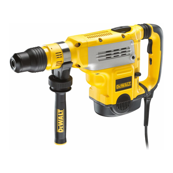
48 mm (1-7/8") sds max combination hammer
Hide thumbs
Also See for D25722:
- Original instructions manual (184 pages) ,
- Instruction manual (29 pages) ,
- Original instructions manual (54 pages)
Table of Contents
Advertisement
Available languages
Available languages
Quick Links
¿Dudas? Visítenos en Internet: www.dewalt.com
Questions? See us on the World Wide Web at www.dewalt.com
MANUAL DE INSTRUCCIONES
INSTRUCTION MANUAL
D25722
Martillo de combinación SDS Max
48 mm (1-7/8") SDS Max
INSTRUCTIVO DE OPERACIÓN, CENTROS DE SERVICIO Y PÓLIZA DE
GARANTÍA. ADVERTENCIA: LÉASE ESTE INSTRUCTIVO ANTES DE USAR EL
PRODUCTO.
®
de 48 mm (1-7/8")
®
Combination Hammer
Advertisement
Table of Contents

Related Manuals for DeWalt D25722


Summary of Contents for DeWalt D25722
- Page 1 ¿Dudas? Visítenos en Internet: www.dewalt.com Questions? See us on the World Wide Web at www.dewalt.com MANUAL DE INSTRUCCIONES INSTRUCTIVO DE OPERACIÓN, CENTROS DE SERVICIO Y PÓLIZA DE GARANTÍA. ADVERTENCIA: LÉASE ESTE INSTRUCTIVO ANTES DE USAR EL PRODUCTO. INSTRUCTION MANUAL D25722 Martillo de combinación SDS Max...
-
Page 3: Defi Niciones: Normas De Seguridad
1) SEGURIDAD DEL ÁREA DE TRABAJO Defi niciones: Normas a) Mantenga el área de trabajo limpia y bien iluminada. Las de seguridad áreas desordenadas u oscuras propician accidentes. b) No opere las herramientas eléctricas en atmósferas Las siguientes definiciones describen el nivel de gravedad de cada explosivas, como ambientes donde haya polvo, gases advertencia. -
Page 4: Seguridad Personal
f) Si no se puede evitar el uso de una herramienta eléctrica f) Use la vestimenta adecuada. No use ropas holgadas ni en una zona húmeda, utilice un dispositivo de corriente joyas. Mantenga el cabello, la ropa y los guantes alejados residual (residual current device, RCD) de seguridad. - Page 5 e) Mantenimiento de las herramientas eléctricas. Revise alambrado oculto o con su propio cable. Si el accesorio de que no haya piezas en movimiento mal alineadas o corte entra en contacto con un cable «vivo» puede hacer que trabadas, piezas rotas o cualquier otra situación que las partes metálicas de la herramienta eléctrica queden «vivas»...
- Page 6 • Nunca suelte la herramienta hasta que la broca haya Tensión (Voltios) Longitud del cable en metros (m) dejado de girar totalmente. Las brocas en movimiento pueden 120–127 V 0–7 7–15 15–30 30–50 provocar lesiones. 220–240 V 0–15 15–30 30–60 60–100 •...
- Page 7 n o ....velocidad sin • Evite el contacto prolongado con polvo generado por el IPM ....impactos por lijado, corte, esmerilado, taladrado y otras actividades de .....minuto ....... carga construcción. Vista ropas protectoras y lave las áreas de sfpm .....pies de superficie ....
-
Page 8: Uso Previsto
USO PREVISTO FIG. 1 MODO DE AJUSTE DE LA BROCA DE CINCEL Su martillo rotativo ha sido diseñado para aplicaciones profesionales de perforación rotativa y perforación mediante martillo de soldadura. NO use la herramienta bajo condiciones de humedad o en presencia de gases o líquidos inflamables. -
Page 9: Montaje Y Ajustes
EMBRAGUE MECÁNICO DE DOS ETAPAS (FIG. 4) Mango lateral (Fig. 1) El embrague mecánico de dos etapas ofrece al usuario un embrague ADVERTENCIA: Para reducir el riesgo de lesiones corporales, con opciones ajustables de par de torsión. El ajuste del par de torsión SIEMPRE opere la herramienta con el mango lateral debidamente proporciona un mayor control para diversas aplicaciones. - Page 10 5. Para bloquear el conjunto de montaje de la empuñadura lateral, 5. Para desmontar una broca, retire el manguito/collar sujetador del apriete el pomo de fijación (H). portaherramientas y saque la broca del portaherramientas. FIG. 3A Selección del modo de funcionamiento FIG.
- Page 11 FIG. 5 Confi gurar el embrague mecánico de dos etapas (Fig. 4) AVISO: Apague siempre la herramienta antes de cambiar la configuración del control de torsión ya que de lo contrario, podrá dañar la herramienta. Desplace la palanca de control del par de torsión (R) al ajuste de 40 ú...
- Page 12 Interruptor activador (Fig. 1) La posición adecuada de las manos exige que una mano se coloque en la empuñadura lateral (C) y la otra en la empuñadura principal (D). Para poner en marcha la herramienta, presione el interruptor de activación (A). Perforación de percusión (Fig.
-
Page 13: Mantenimiento
8. Cuando taladre en una estructura que sea más gruesa que la Lubricación profundidad de la barrena hueca, deberá sacar con frecuencia el La herramienta eléctrica no requiere lubricación adicional. cilindro de hormigón que se acumulará en la barrena hueca. Escobillas (Fig. -
Page 14: Protección Del Medio Ambiente
WALT o a un centro de reciclaje, donde expertos podrán reciclar y reutilizar los materiales. Revise las normativas locales para reciclaje de productos eléctricos tales como herramientas y electrodomésticos, allí podrá encontrar centros de reciclaje municipales. ESPECIFICACIONES D25722-AR D25722-B3 Voltaje 220 V ~ 120 V ~ Frecuencia 50 Hz 50–60 Hz... -
Page 15: Save All Warnings And Instructions For Future Reference
c) Keep children and bystanders away while operating a Defi nitions: Safety Guidelines power tool. Distractions can cause you to lose control. The definitions below describe the level of severity for each 2) ELECTRICAL SAFETY signal word. Please read the manual and pay attention to these a) Power tool plugs must match the outlet. - Page 16 d) Store idle power tools out of the reach of children and skid safety shoes, hard hat, or hearing protection used for do not allow persons unfamiliar with the power tool or appropriate conditions will reduce personal injuries. these instructions to operate the power tool. Power tools c) Prevent unintentional starting.
- Page 17 or against your body is unstable and may lead to loss of control. wrapped around a spinning bit may cause personal injury and loss of control. • Wear safety goggles or other eye protection. Hammering operations cause chips to fly. Flying particles can cause permanent •...
- Page 18 • crystalline silica from bricks and cement and other masonry ....Class I Construction or AC/DC ...alternating products, and ..... (grounded) ......or direct • arsenic and chromium from chemically-treated lumber....Class II Construction current Your risk from these exposures varies, depending on how often you n o ....no load (double insulated) do this type of work.
-
Page 19: Intended Use
INTENDED USE FIG. 1 CHISEL BIT ADJUSTMENT MODE Your rotary hammer has been designed for professional rotary drilling and chipping applications. DO NOT use under wet conditions or in presence of flammable liquids or gases. This heavy-duty rotary hammer is a professional power tool. DO NOT HAMMERDRILLING CHIPPING MODE let children come into contact with the tool. -
Page 20: Assembly And Adjustments
TWO-STAGE MECHANICAL CLUTCH (FIG. 4) Side Handle (Fig. 1) Two-stage mechanical clutch offers the user a clutch with adjustable WARNING: To reduce the risk of personal injury, ALWAYS operate torque options. Adjusting the torque provides increased control for the tool with the side handle properly installed and securely tightened. various applications. - Page 21 Selecting the Operating Mode (Fig. 1) Setting the Electronic Speed and Impact Hammerdrilling: for concrete, brick, stone and masonry Control Dial (Fig. 1, 4) drilling operations. FIG. 4 Turn the dial (G) to the desired Hammering only: for chiselling and demolition applications. level.
-
Page 22: Operation
Indexing the Chisel Position (Fig. 5) WARNING: The use of a residual current device (RCD) protected supply with a rated residual current of 30 mA or The chisel can be indexed and locked into 24 different positions. less is recommended. The use of a RCD reduces the risk of 1. - Page 23 Hammerdrilling (Fig. 1) Chipping and Chiselling (Fig. 1) To turn the tool on, press the on/off switch (A). 1. Insert the appropriate chisel and rotate it by hand to lock it into one of 24 positions. To stop the tool, release the switch. 2.
-
Page 24: Protecting The Environment
SPECIFICATIONS D25722-B3 Accessories Voltage 120 V ~ WARNING: Since accessories, other than those offered by... - Page 28 HECHO EN REPÚBLICA CHECA R.F.C.: BDE810626-1W7 MADE IN CZECH REPUBLIC WALT Industrial Tool Co., 701 East Joppa Road, Baltimore, MD 21286 (SEP13) Part No. N330562 D25722 Copyright 2013 D WALT © The following are trademarks for one or more D WALT power tools: the yellow and black color scheme;...