Hitachi NR 90AE Technical Data And Service Manual
Strip nailer
Hide thumbs
Also See for NR 90AE:
- Instruction and safety manual (18 pages) ,
- Instruction and safety manual (68 pages) ,
- Instruction and safety manual (64 pages)

Related Manuals for Hitachi NR 90AE


Summary of Contents for Hitachi NR 90AE
- Page 1 MODEL NR 90AE Hitachi Power Tools TECHNICAL DATA STRIP NAILER NR 90AE SERVICE MANUAL LIST No. E030 Dec. 2005 SPECIFICATIONS AND PARTS ARE SUBJECT TO CHANGE FOR IMPROVEMENT...
- Page 2 REMARK: Throughout this TECHNICAL DATA AND SERVICE MANUAL, a symbol(s) is(are) used in the place of company name(s) and model name(s) of our competitor(s). The symbol(s) utilized here is(are) as follows: Competitors Symbols Utilized Company Name Model Name D51845 Dewalt F-350SRH PASLODE 700XL...
-
Page 3: Table Of Contents
10-4. Disassembly and Reassembly of the Driving Section ............... 26 10-5. Disassembly and Reassembly of the Cap and the Magazine Section ........29 11. INSPECTION AND CONFIRMATION AFTER REASSEMBLY ..........33 12. STANDARD REPAIR TIME (UNIT) SCHEDULES ..............34 Assembly Diagram for NR 90AE... -
Page 4: Product Name
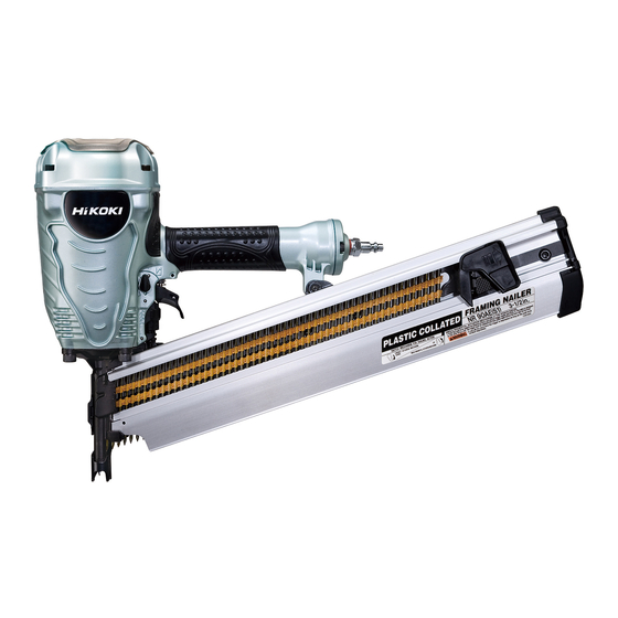
The Model NR 90AE is a framing nailer for round head nails. This is developed as a next-generation nailer with an all-new design in order to expand our market share. The main features of the Model NR 90AE are as follows: (1) Lightweight (3.4 kg) and good balance... -
Page 5: Specifications
5. SPECIFICATIONS 5-1. Specifications NR 90AE Model Driving system Reciprocating piston type 5 -- - 8.5 kgf/cm (70 -- - 120 psi, 4.9 -- - 8.3 bar) (Gauge pressure) Operating pressure Driving speed 3 pcs./sec. Weight 3.4 kg (7.5 lbs.) -
Page 6: Explanation Of The Nailing Action
5-2. Explanation of the Nailing Action To meet the requirements of "ANSI SNT-101-2002", the Model NR 90AE is equipped with a nailing operation switching device at the valve portion as shown in the figures below. Use SINGLE ACTUATION MECHANISM (SINGLE SEQUENTIAL ACTUATION MECHANISM) or CONTACT ACTUATION MECHANISM in accordance with the work to be performed. -
Page 7: Nail Selection
NR 90AD. CAUTION: Ensure that nails are as specified in Fig. 1. The Model NR 90AE utilizes full-round head nails collated at an angle of 21 degrees which are the same as the nails utilized by the Model NR 83A2. However, some round head nails made by other makers are collated at a different angle. -
Page 8: Nail Driving Force
For example, when driving a nail of 3.3 mm dia. by 90 mm length (0.131" x 3-1/2") into nine sheets of 12 mm plywood (108 mm thick ) with the Model NR 90AE, a pressure of about 7.5 bar (7.6 kgf/cm , 108 psi) allows the nailer to drive the nail flush with the wood surface. -
Page 9: Comparisons With Similar Products
--- 6 ---... -
Page 10: Precautions In Sales Promotion
7. PRECAUTIONS IN SALES PROMOTION In the interest of promoting the safest and most efficient use of the Model NR 90AE Nailer by all of our customers, it is very important that at the time of sale the salesperson carefully ensures that the buyer seriously recognizes the importance of the contents of the Handling Instructions, and fully understands the meaning of the precautions listed on the Warning Label attached to each tool. -
Page 11: Related Laws And Regulations
7-3. Related Laws and Regulations As nailers and staplers are designed to instantaneously drive nails and staples, there is an ever-present danger of misfiring and subsequent possible serious injury. Accordingly, close attention in handling is absolutely necessary at all times. Carefully ensure that the customer is fully aware of the precautions listed in the Handling Instructions provided with each unit. -
Page 12: Mechanism And Operation Principle
Output section, control valve section, driving section and magazine section. Although the basic construction of the Model NR 90AE is the same as that of the Model NR 90AD chiefly, the driving section and the magazine section are newly designed. - Page 13 Head Guard [2] Exhaust Cover [5] Head Valve [9] Control valve section Exhaust Valve Cap [40] Rubber [11] Accumulator Piston [13] (Driver blade) Cylinder [15] Body Ass'y [24] Piston Bumper [30] Nose [28] Pushing Lever (A) [34] Control valve section Valve Piston [65] Plunger Spring [67] Valve Bushing (B) [62]...
-
Page 14: Operation Principle
8-2. Operation Principle (1) Before nailing (See Fig. 4 and Fig. 5.) Exhaust Valve Rubber [11] 1) When compressed air is fed to the main body, it Head Valve Head valve chamber Spring [7] fills the accumulator ( portion). 2) At the same time, the compressed air flows into Air passage Head Valve [9] Control... - Page 15 (3) During return (See Fig. 6 and Fig. 7.) Exhaust Valve Rubber [11] 1) When either Pushing Lever (A) [34] or Trigger (C) Exhaust vent Head valve chamber Head Valve [49] is released, the Plunger [69] goes down and Spring [7] the compressed air in the accumulator flows into Air passage Head Valve [9]...
- Page 16 (4) Single actuation mechanism/contact actuation mechanism: (Fig. 8 and Fig. 9) Single/contact actuation mechanism changeover is accomplished by turning the switching device (Change Knob (C) [45]). Single actuation mechanism (Switching device: Accumulator upward position): 1) Immediately after driving the first nail, the control valve should be as shown in Fig.
-
Page 17: Troubleshooting Guide
9. TROUBLESHOOTING GUIDE 9-1. Troubleshooting and Correction Problem Possible cause Inspection method Remedy 1) Nails cannot <Nails> be driven. Magazine is not loaded with Check if the magazine is Use specified nails. specified genuine nails. normally loaded with Remove the abnormal nails specified nails. - Page 18 Problem Inspection method Remedy Possible cause < Output section > Air pressure is too low. Adjust for 5 to 8.5 kgf/cm Pull the nail feeder Replace the piston O-ring. backward and perform idle Piston O-ring is worn or driving. Check if the driver damaged.
- Page 19 Possible cause Problem Inspection method Remedy Adjust the adjuster to the 3) Head of a nail Turn the adjuster to the Adjuster is improperly proper position. driven into a adjusted. lowest position and drive a workpiece nail. Adjust for 5 to 8.5 kgf/cm protrudes Air pressure is too low.
-
Page 20: Possible Causes And Correction Of Air Leakage
9-2. Possible Causes and Correction of Air Leakage Repair procedure Air leakage repair location (1) Check the points of the following parts marked by an asterisk * for abnormal condition. (2) Next, check the seal parts marked with a double circle for wear, flaw and damage. - Page 21 Possible cause Air leakage point With control valve OFF With control valve ON C) Nose 1 The O-ring (I.D 60) [31] of the Nose [28] or the groove is abnormal (broken or flawed). The Nylock Hex. Socket Hd. Bolt M8 x 30 [29] is loose.
-
Page 22: Disassembly And Reassembly
10. DISASSEMBLY AND REASSEMBLY The items particularly necessary for disassembly and reassembly are described below. The [Bold] numbers in the descriptions below correspond to the item numbers in the Parts List and exploded assembly diagram. [CAUTION] Before disassembly or reassembly, be sure to remove all nails and disconnect the air hose from the nailer (with your finger released from the trigger) to exhaust all the compressed air. -
Page 23: Disassembly And Reassembly Of The Output Section
10-2. Disassembly and Reassembly of the Output Section (1) Disassembly and reassembly of the Exhaust Cover [5], Head Valve [9], Exhaust Valve Rubber [11], etc. (See Fig. 11A and Fig. 11B.) [Tools required] Hex. Socket Hd. Bolt Hex. bar wrench (4 mm, 5 mm) M5 x 14 [1] Hammer Head Guard [2]... - Page 24 (a) Reassembly Disassembly procedures should be followed in the reverse order. Note the following points. Charge the sliding portion of the Head Valve [9] of the Exhaust Cover [5] with about 3 grams of grease and apply grease to each surface of the O-rings. As shown in Fig.
- Page 25 (2) Disassembly and reassembly of the Cylinder [15], Piston [13], Piston Bumper [30], etc. (See Fig. 14.) (a) Disassembly Remove the Exhaust Cover [5] as described in item (1). Now, the Cylinder [15], Cylinder Plate [17], Piston [13], Piston Bumper [30], etc. can be taken out. (b) Reassembly Disassembly procedures should be followed in the reverse order.
-
Page 26: Disassembly And Reassembly Of The Control Valve Section
10-3. Disassembly and Reassembly of the Control Valve Section (See Fig. 15.) [Tools required] Flat-blade screwdriver Roll pin puller (3 mm (0.118") dia.) (a) Disassembly Remove the Retaining Ring (E-type) for D6 Shaft [22] with blade of a screwdriver and pull out Change Knob (C) [45] being careful not to lose the Steel Ball D3.97 [43] and Spring (C) [44]. - Page 27 Pull out the Roll Pins D3 x 25 [20] and Push D3 x 32 [21] with the roll pin puller (3 mm dia.), and take out the control valve in the following manner. 1) Remove the Exhaust Cover [5] by following Body Ass'y [24] the procedure in (1), item 10-2.
- Page 28 (b) Reassembly Disassembly procedures should be followed in the reverse order. Note the following points. Be extremely careful to prevent the entry of foreign particles into the control valve section. Thoroughly apply grease to the O-Rings (I.D 1.8) [68] of the Plunger [69], the O-Rings (P-7) [64] and (1AP-10) [66] of the Valve Piston [65].
-
Page 29: Disassembly And Reassembly Of The Driving Section
10-4. Disassembly and Reassembly of the Driving Section (See Fig. 19.) [Tools required] Hex. bar wrench (5 mm and 6 mm) Roll pin puller (2.5 mm (0.098") dia.) Wrench M6 (1) Disassembly and resassembly of Nose [28], Pushing Lever (A) [34] and other parts (a) Disassembly Holding the Handle Arm [71], remove the Hex. - Page 30 (b) Reassembly (See Fig. 20.) Disassembly procedures should be followed in the reverse order. Note the following points. Apply grease to the O-ring (I.D 60) [31] and mount it in the groove of the Nose [28]. Insert Pushing Lever Springs (A) [51] and (B) [50] between the protrusion of Pushing Lever (C) [52] and the protrusion of the Pushing Lever Guide [47].
- Page 31 (2) Disassembly and reassembly of the adjuster unit (a) Disassembly (See Fig. 22.) Remove the Retaining Ring (E-type) for D3 Shaft [60]. Then Pushing Lever (A) [34] and the adjuster unit can be separated. Pull out the Roll Pin D2 x 16 [54]. Then the adjuster unit can be disassembled. (b) Reassembly Disassembly procedures should be followed in the reverse order.
-
Page 32: Disassembly And Reassembly Of The Cap And The Magazine Section
10-5. Disassembly and Reassembly of the Cap and the Magazine Section (1) Magazine [76], Nail Feeder Ass'y [87] and the related parts (See Fig. 23.) [Tools required] Hex. bar wrench (5 mm) Wrench M6 Roll pin puller (3 mm (0.118") dia.) Wooden hammer A cross-head screwdriver (a) Disassembly... - Page 33 Magazine section Nail Feeder Ass'y [87] Nose [28] 0.05" max. Magazine [76] (1.3 mm max.) Fig. 23 --- 30 ---...
- Page 34 Sleeve [73] Nylon Nut M6 [72] Magazine Cover [74] Hex. Socket Hd. Rear Bolt M6 x 22 [35] Handle Arm [71] Protrusion Nylon Nut M6 [72] Magazine [76] Nail Rail [75] Hex. Socket Hd. Nylon Nut M4 [88] Bolt (W/Flange) M6 x 12 [77] Needle Roller D4 x 20 [81]...
- Page 35 (b) Reassembly Disassembly procedures should be followed in the reverse order. Note the following points. When inserting the Roll Pin D4 x 36 [79] into Nail Feeder (B) [80], be careful that the end of the Roll Pin D4 x 36 [79] is not stick out from Nail Feeder (B) [80]. Insert the Feeder Spring [83] between the protrusion of Nail Feeder (A) [78] and the protrusion of Nail Feeder (B) [80].
-
Page 36: Inspection And Confirmation After Reassembly
Set Change Knob (C) [45] to "single actuation (single sequential actuation)" (see 5-2). Check that the Model NR 90AE operates by pressing Pushing Lever (A) [34] against a test piece first then pulling Trigger (C) [49]. Check that the Piston [13] is still showing from the Nose [28] tip (outlet of nails) after Pushing Lever (A) [34] is released from the test piece with Trigger (C) [49] pulled. -
Page 37: Standard Repair Time (Unit) Schedules
12. STANDARD REPAIR TIME (UNIT) SCHEDULES Variable 60 min. MODEL Fixed Work Flow NR 90AE Exhaust Cover Head Valve Spring Nose O-ring x 2 Nail Feeder Head Valve Ass'y Exhaust Valve Magazine Cover Rubber Magazine Nail Feeder (A) Nail Feeder (B) - Page 38 Hitachi Power Tools LIST NO. E030 PNEUMATIC TOOL PARTS LIST STRIP NAILER 2005 • • Model NR 90AE (E2) 81 82...
- Page 39 PARTS NR 90AE ITEM CODE NO. DESCRIPTION REMARKS USED 949-665 HEX. SOCKET HD. BOLT M5X14 (10 PCS.) 884-952 HEAD GUARD 884-986 SHEET 878-877 HEX. SOCKET HD. BOLT (W/FLANGE) M6X30 884-951 EXHAUST COVER 884-953 GASKET (A) 884-949 HEAD VALVE SPRING 884-947 O-RING (I.D 49.4)
- Page 40 PARTS NR 90AE ITEM CODE NO. REMARKS DESCRIPTION USED 884-972 PUSHING LEVER (C) 884-974 ADJUSTER 880-093 ROLL PIN D2X16 882-890 ADJUSTER SPRING 884-973 ADJUSTER PLATE (C) 882-886 ADJUSTER PLATE (A) 884-971 PUSHING LEVER (B) 872-822 O-RING (S-5) 872-971 RETAINING RING (E-TYPE) FOR D3 SHAFT 877-763 FEED PISTON O-RING (I.D.14)
-
Page 41: Standard Accessories
STANDARD ACCESSORIES NR 90AE ITEM CODE NO. DESCRIPTION REMARKS USED 875-769 SAFETY GLASSES OPTIONAL ACCESSORIES ITEM CODE NO. DESCRIPTION REMARKS USED 881-768 GRIP TAPE (A) 880-407 TAPE --- 4 --- Printed in Japan 12 -- 05 * ALTERNATIVE PARTS (051205N)