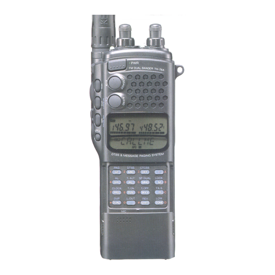
Kenwood TH-78A Instruction Manual
144/430, 144/440 fm dual banders
Hide thumbs
Also See for TH-78A:
- Service manual (114 pages) ,
- Instruction manual (72 pages) ,
- Instructions (4 pages)

Related Manuals for Kenwood TH-78A


Summary of Contents for Kenwood TH-78A
-
Page 1: Instruction Manual
144/430 MHz FM Dual Bander 144/440 MHz FM Dual Bander TH-78A 144/430MHz FM Dual Bander TH-78E INSTRUCTION MANUAL KENWOOD CORPORATION @PRINTED IN JAPAN B62-0248-30(W)(MC) 9 4 / 6 5 4 3 2 1 9 3 / 1 2 1 1 1 0 9 8 7 6 5 4 3 2... -
Page 2: Table Of Contents
ACCESSORIES ....BEFORE OPERATION ....Controls Overview ....THE BATTERY PACK 1 NiCd Battery Pack (PB-13). - Page 3 THE DUAL TONE SQUELCH SYSTEM (DTSS) 1 DTSS Code......36 2 Using the DTSS Function ....36 3 Using DTSS with a Repeater.
-
Page 4: Accessories
BEFORE OPERATION T90-0444-X X Thank you for purchasing this KENWOOD J29-0465-X X transceiver. To get the most out of its many features, J69-0312- X X we suggest you read this instruction manual B09-0330- X X carefully, and keep it handy for further reference. -
Page 5: Controls Overview
Controls Overview This transceiver has different key layouts for each destination. Check the version of your transceiver first by looking at the following illustration. U.K and Europe version only All types except U.K and European version... - Page 6 This diagram will help you locate the keys, switches, and knobs you’ll need to perform necessary operations. Please study these controls carefully. By the time you reach the end of this manual, you will have had to use each of them many times. All types except U.K and European version ANTTENA CONNECT...
-
Page 7: Nicd Battery Pack (Pb-13)
1 NiCd Battery Pack (PB-13) You must charge the battery before you can use it. It has not been charged at the factory in order to provide you with the greatest number of charge/ discharge cycles. It takes several charge/discharge cycles before the battery pack will operate for its maximum period. -
Page 8: Battery Voltage Level
4 Battery Voltage Level Output power: EL The meter indicates the relative battery voltage during transmit. Recharge or replace the batteries when the level reaches the low indicator. NiCd Battery pack Manganese or Alkaline Batteries Load 6 X R6 (AA) manganese or alkaline batteries in series in the optional battery case(BT-8). -
Page 9: Receiver Operation
1 Getting Started Connect the battery pack and the supplied antenna. Press the POWER switch to turn the transceiver on. One of the default frequencies should appear on the display. If the display shows incomplete data, or you think the displayed frequency is wrong, reset the micro- processor Memory Initialization (see page 19) RECEIVER OPERATION... - Page 10 When you press the BAND key, control of each function is transferred to the VHF band. When you press and hold the E.CHG key (or within two seconds of pressing the E.CHG key), each control temporary control of the volume or tuning control passes to the VHF band.
-
Page 11: Selecting Frequency
Whenever you are selecting frequencies, your first step should be to set the squelch control. The squelch helps eliminate “white noise” or static until you receive active communications on a frequency. There are two squelch controls, one for the UHF band and one for the VHF band. - Page 12 For the European version and some other markets, Next press numeric keys 0 and 5. 5 The transceiver actually changes frequency only after the 1 kHz digit is entered. The 1 kHz digit is not displayed if it is a zero. If you do not enter the 1 kHz digit, the indicator flashes and the transceiver defaults to the previous operating frequency.
-
Page 13: Step Size Selection
Using the Tuning Control The tuning control selects frequencies in up or down sequentially. Rotate the tuning control clockwise or counterclockwise to select the desired operating frequency. 4 Step Size Selection The transceiver must be in the VFO mode to select frequency steps. -
Page 14: Programmable Vfo Tuning Limits
To step size 5,10, 15, or 20 From step size 12.5 or 25 Frequencies Display as 12.5 37.5 62.5 87.5 5 Programmable VFO Tuning Limits This radio provides the capability of programming the VFO tuning range, in 1 MHz band segments, as well as providing a separate programmable band scan function. -
Page 15: Basic Receiving Functions
5 To confirm that the programming was properly performed rotate the Tuning control. The transceiver should not go above or below the programmed band limits. VFO tuning range 146.000 144.000 145.000 To clear the programmed limits simultaneously reset the VFO memory using the procedures discussed on page 19. -
Page 16: Transmitter Operation
WARNING: Before you attempt to transmit, attach an antenna with a low standing wave ratio to the antenna connector. Failure to provide a proper load may cause damage to the final amplifier section. Always check that the frequency is clear before transmitting. 1 To transmit, follow these steps: 1 Use any of the frequency selection methods discussed on page 12 to select an operating... -
Page 17: Tx. Stop Function
No indicator means the high power position has been selected. Use high power for maximum transmitter power. See the high power CAUTION on page 5. Output Power(watts) 144MHz 0.02 2.0 PB-13,18 0.02 5.0 0.02 2.0 Alkaline Battery I 0.02 5.0 3 TX. -
Page 18: Using The Memory
1 Microprocessor Memory Backup All memory channel data is backed up in EEPROM. It is not lost unless you reset the memory. All other data that you set is retained by a secondary lithium battery that will provide memory backup for about 20 days if you remove the battery pack or external DC power. -
Page 19: Memory Contents
4 Memory Contents Each memory channel can store information as shown in the chart below. X =Can be stored in memory Normal Channel RX frequency TX frequency Tone(CTCSS) frequency, Tone (CTCSS) status Frequency step Shift status, REV on/off DTSS code. DTSS status 5 Entering Memory Data Entering memory data is a simple operation requiring just a few keystrokes to store all the data you... -
Page 20: Entering Split Channel Frequencies
6 Entering Split Channel Frequencies Use the numeric keypad to select the desired receiver frequency, tone and other information. If the desired frequency is already on the display, continue to step 2. Press the M key. The memory indicator will flash. Use the keypad to select any desired memory channel number (O-49). -
Page 21: Recalling Memory Channels
3 Select the desired call channel transmit frequency. 4 Press the M key. 5 Press and hold the PTT switch and press the CALL key. 6 Release the PTT switch. 8 Recalling Memory Channels Press the MR key. You can change the memory channel by the following two methods. -
Page 22: Memory Channel Character Display
10 Memory Channel Character Display You can display the memory channel frequency with your own spelling. It may be up to six characters long. You can use numerics 0 to 9 and the letters A to z. Function Setting Press and hold the f² key, and turn the power on. Note When you select this function, the memory channel can be displayed alphanumerically, but the total... -
Page 23: Scanning
You must adjust the squelch to the threshold point for proper scan operation. You cannot use scan in conjunction with the tone alert function and paging. Scanning occurs separately in the VHF and UHF bands. You can reverse the direction by turning the Tuning control or MESSAGE key. -
Page 24: Scan Options
3 Scan Options The following scan options are available: * Memory Scan Scans through those memory channels that have data stored and that have not been locked out. This function operates only in the memory mode. * Band Scan Scan proceeds over the entire band. This function operates only in the VFO mode. -
Page 25: Scanning Band
2 Press the F key, then the 0/L.OUT key. A * indicator appears below the memory channel number on the display, indicating that channel will be skipped in the memory channel scan mode. 3 Repeat steps 1 and 2 to lockout any other channels you may want to skip. -
Page 26: Mhz Scan
5 Press and hold the M key for longer than one second, then press the 4 key. Notes 1 Initialize the VFO memory (VFO RESET) to clear both programmed limits simultaneously. Press and hold the F key and turn on the power. You can reprogram either limit independently. -
Page 27: Call/Vfo Scan
2 Press the F key, then press the MR key. 3 The VFO frequency and the last used memory channel are scanned alternately. 9 CALL/VFO Scan Press and hold the CALL key for longer than one second in VFO mode. 2 The frequency and CALL frequency are scanned alternately. -
Page 28: Repeater Operation
- - . REPEATER OPERATION 3 Automatic Offset Selection U.S.A. and CANADA versions The TH-78A is programmed according to the standard ARRL(Amateur Radio Relay League) Band Plan for repeater offset direction. You can override this programming by using the SHIFT key as described in the preceding paragraph. -
Page 29: Manual Offset Selection
4 Manual Offset Selection The factory default sets the automatic offset frequency. You can select any offset frequency in the range 0 to 99.9 MHz in 100 kHz steps. Press and hold the SHIFT/REV key and switch the power on. 2 Press the F key for longer than one second, then press the SHIFT/REV key. -
Page 30: Tone Operation
6 Tone Operation Some repeaters require a control signal to activate them. Several different methods are currently in use. In the United States, sub-audible tones are sometimes used. This transceiver will generate sub- audible frequencies. In Europe and the United Kingdom, a 1750 Hz tone is used in transmitting. -
Page 31: Autopatch Operations
7 Autopatch Operations (U.S.A. versions only) Some repeaters offer a service called autopatch. This feature allows you to dial a telephone number from your transceiver and carry on a telephone conversation. This function requires the use of a DTMF (Dual Tone Multi Frequency) keypad. -
Page 32: Dtmf Memory
8 DTMF Memory You can store 10 DTMF telephone numbers up to a maximum of 15 digits long in memory. Storing DTMF Codes Press the M key, then press the MHz key to select the DTMF code entry mode. 2 Enter the DTMF code on the keypad 3 Press the MR key after entering the DTMF code. -
Page 33: Operation As A Repeater
Making a DTMF Call 1 Hold the PTT switch down and press the MHz key. 2 Press the numeric key (O-9) for the channel where the DTMF code is stored. 3 The DTMF code appears on the display. Note Transmission continues until the whole code string is recalled, even if the PTT switch is released. -
Page 34: Ctcss Operation
The CTCSS unit (TSU-7) is included only with models delivered to the United States and Canada. The CTCSS unit (TSU-7) installation instruction are shown on page 63. If the Continuous Tone Code Squelch System (CTCSS) function is activated, the transceiver will not open squelch until it receives the proper PL tone (tone squelch). -
Page 35: The Dual Tone Squelch System (Dtss)
THE DUAL TONE SQUELCH SYSTEM (DTSS) DTSS allows squelch activation in the receive mode when the transceiver receives a three-digit code matching the DTSS code you have selected. Once squelch is activated, it operates normally from then on. If no signal is received for more than two seconds, squelch turns off until the transceiver receives a matching code. -
Page 36: Paging Operation Overview
Paging uses a DTMF (Dual Tone Multi Frequency) signal and is useful in calling members of a group, a specific station, or for waiting for a call from another station. F: 145.020MHz Individual Code: 111 F: 145.020MHz F: 145.020MHz lndividual Code 222 lndividual Code: 333 Member 2 Member 1... -
Page 37: Paging Code Memory
2 Paging Code Memory There are 8 paging code memories. M e m o r y C o d e Stores your station ID code in memory. Automatically stores the calling station’s code during reception. Can temporarily set the code for the station to be called. Stores group codes and local station codes 1 ~ 6 in memory. -
Page 38: Sending Pages (Calling)
The chart shows how members of a group might communicate with each other. You may wish to refer back to this chart as you read the examples on the following gages. Your station ID code is preset in memory A. You Group Communication Network Example Predetermined frequency Your Individual code... - Page 39 Press the PTT switch. Communication is possible in both the Paging and code setting mode. In the code setting mode In the Paging mode The group code 789 and your station ID code 111 are transmitted. Calling a Specific Group Member Use the following procedure to call a specific group member: 1 Select the local station code memory.
-
Page 40: Receiving Pages Wait)
5 Receiving Pages (Wait) 1 Tune to the predetermined frequency. 2 Press the F key then press the 1 key to enter the Paging mode. Receiving a Page with an Individual Code 1 When the proper code is received, your squelch will open and you will hear an alert tone sequence coming from the speaker. -
Page 41: Canceling Signal Squelch
6 Canceling Signal Squelch Squelch will not open when operating in the paging mode when the paging codes do not match. It is possible to reprogram the transceiver so that squelch will open regardless of the incoming page code. Even when signal squelch is canceled, a beep sounds and the individual code of the local station is displayed when the proper code is received. -
Page 42: Message Transmission And Reception
MESSAGE TRANSMISSION AND RECEPTION This function lets you transmit your message to the other party or display a message from the other party on your transceiver using the DTMF (Dual Tone Multi Frequency) signal and alphanumeric display. You can use the numerics 0 to 9 and letters A to Z. The message that can be transmitted and received at one time can be up to six characters long. - Page 43 Relationship between input characters and keys (Note: “ + ” means press two keys in sequence (with in 2 seconds)) lnpu t characters operation lnput characters operation 1+B (M) (space) 2 + B ( M ) 3+B (M) 4 + B ( M ) 5+B (M) 6+B (M) 7+B (M)
-
Page 44: Message Memory Check
5 Press a key (0 to 9) corresponding to the numeric you want to enter to memory. 6 To cancel message input mode, press the PTT switch. 3 Message Memory Check 1 Press and hold the F key for longer than one second, then press the MESSAGE key. -
Page 45: Receive Message Memory
H Paging mode Press any key 6 Receive Message Memory This transceiver has 10 incoming message memory channels, in which received messages are stored. If you press the MESSAGE key in the message mode, the last stored message is displayed. You can store your message in memory using one of the following two methods. -
Page 46: Enhanced Receiver Functions
ENHANCED RECEIVER FUNCTIONS 1 The Tone Alert System The Tone Alert function provides an audible alarm to indicate when someone is transmitting on the frequency you are monitoring. If you use the tone alert function with the CTCSS, paging, or DTSS function, you can use the functional more effectively since you can wait for a call from a specific remote station. -
Page 47: Monitor
2 Monitor Even if the squelch or CTCSS, DTSS, or PAGING is ON, you can monitor the channel by pressing the MONI key. 3 BeepOff The transceiver produces beeps when you push the front panel keys. If you want to disable this function, press and hold the 6 key and press the POWER switch. -
Page 48: Volume Adjustment When You Use Anearphone
6 Volume adjustment when you use an earphone CAUT/ON If you use an earphone, you may feel that the volume is too high even if the volume level is set to minimum. We recommend that before connecting the earphone, you set the volume level to the minimum and perform the following operation to protect your ears. -
Page 49: Automatic Band Change Function
8 Automatic Band Change Function The Automatic Band Change function automatically switches transmit control from the RX/TX band to the RX only band whenever a signal is received that opens squelch on the RX only band. 1 Press the F key, then press the BAND/A.B.C. key within 10 seconds. -
Page 50: Single Band Operation
Notes on simultaneous in Band reception 1 When two signals on the same band are received simultaneously, the receive performance, such as image interference and sensitivity, may be reduced. 2 If the two frequencies are the same, the volume may decrease at some VOL control positions. -
Page 51: Power Saver Features
1 The Battery Saver Mode This transceiver provides a battery saver mode to conserve on battery power. The battery saver circuit activates 10 seconds after the last key is pressed. The squelch must be closed. This function deactivates whenever a key is pressed or the squelch opens. -
Page 52: Clock Function
If you press the F key, then the 7 key in receive mode, the clock is displayed on the Sub band display. The time is displayed on a 24-hour basis. If you press the F key, then the 7 key again, the clock is canceled, and the normal frequency display returns. - Page 53 Switch-off Timer Setting 1 If you press and hold the F key for longer than one second, then the 9 key, you enter the switch-off timer setting mode, and the TIMER.OFF indicator and the “Hour” display will flash. 2 Set the “Hour” display to the time you want the transceiver to turn off with the Tuning control.
-
Page 54: Duplex Operation
Normally this transceiver operats in a simplex mode, i.e. No receive audio from the sub-band is fed to the speaker during transmit on the main or active band. If you prefer duplex operation, i.e. Receive audio from sub-band is fed to the speaker during transmit you must perform the following procedure. -
Page 55: Power On Message And Function Message
POWER ON MESSAGE AND FUNCTION MESSAGE 1 Power On Message When you first switch the POWER on, “TH78A” or “TH78E” appears on the display for two seconds. You can change this factory-set message to your own message as follows: Changing Power-on Message 1 Select your message by following steps 1 to 4 of the memory write procedure on page 44. - Page 56 Earphone mode MSG M1 Store receive messages in up to 10 memory channels MSG MX If more than 10 messages are received, the oldest message are replaced with the new ones MSGCLR Message transmission memory clear OPG OFF Signal squelch ON OPG ON Canceling signal squelch PROGSCN...
-
Page 57: Maintenance
1 General Information Your transceiver has been factory aligned and tested to specification before shipment. Under normal circumstances the transceiver will operate in accordance with these instruction manuals. All adjustable trimmers and coils in your transceiver has been adjusted at the factory and should only be readjusted by a qualified technician with proper test equipment. -
Page 58: Troubleshooting
The following problems are generally caused by improper transceiver operation or connection, not by defective components. Symptom Indicators do not light and no receiver noise is heard when the POWER switch is turned on. No sound from the speaker. No signal can be received. No control works. -
Page 59: Accessories
Note: Some optional accessories may not be available in your area. SPEAKER MICROPHONE SMC-31 SMC-32 CLIP MICROPHONE with EAR PHONE SMC-33 ACCESSORIES Optional unit SMC-34 TSU-7 (CTCSS unit) HEADSET with VOX/PTT HMC-2 ME-1 (Memory expansion unit) EMC-l Battery charger (Wall charger) BC-15A... - Page 60 DVB lNVlSIS3tl lNflOk-4 13AIMS...
-
Page 61: Installing The Ctcss Unit (Tsu-7)
1 Installing the CTCSS Unit (TSU-7) 1 Slide the release button to unlock, then pull out the battery case. 2 Unscrew the four screws on the rear (Fig. 1). The screw near the antenna connector is a short one. 3 Put your finger into the battery holder, and release the claw of the rear case. -
Page 62: Memory Expansion Unit (Me-L)
2 Memory Expansion Unit (ME-l) 1 Slide the release button to unlock, then pull out the battery case. 2 Unscrew the four screws on the rear (Fig. 1). The screw near the antenna connector is a short one. 3 Put your finger into the battery holder, and release the claw of the rear case. -
Page 63: Programming The Smc-33 Remote Control Speakermicrophone
3 Programming the SMC-33 Remote Control Speaker Microphone switch LOCK switch These keys function just like the VFO, MR, and CALL keys on the front panel of the transceiver. To reset the function of the transceiver keys. 1 Connect the SMC-33 to the MIC jack on top of the transceiver. - Page 64 Memory Control Functions Press the F key, then the Press the key below. key below. Tuning control (II) Encoder/Volume selecting mode LAMP (Turns off 5 seconds after the (Does not turn off automatically) last key operation) MONI TX output power selection TONE Memory shift CALL...
-
Page 65: Using Other Microphone
4 Using Other Microphone If not using the SMC-33, we recommend using an electret type microphone. The input impedance is 2k ohms and the DC voltage on the microphone terminal is approximately 4 volts (Max. 3.5 mA). Do not use a dynamic microphone. Speaker... -
Page 66: Specifications
1 4 4 M H z GENERAL U.S.A. Version FREQUENCY RANGE (MHz) U.K.and Europe 144 to 146 Other market 144 to 148 ANTENNA IMPEDANCE OPERATING TEMPERATURE POWER REQUIREMENTS BATTERY PACK Approx. CURRENT DRAIN Transmit mode(13.8VDC) Transmit mode(13.8VDC) Transmit mode(13.8VDC) 120mA SIMPLEX Receive mode with no signal SIMPLEX... -
Page 67: Quick Reference
Note : The plus symbol (+) means press two keys simultaneously. “(1 second)” means press the key for longer than one (1) second. TO DO THIS Temporarily change the volume or frequency of the band that cannot control DetermIne if a frequency is in use before transmitting The LCD illumination lamp lights Change the frequency in 1 MHz step... - Page 68 Switching speaker output when a external Turn CLOCK function on or off Turn switch on timerfunction on or off Turn switch off timerfunction on or off Activate memory channel lock out function Turn KEY LOCK function on or off Turn TX STOP function on or off Select transmit output power level Activate duplex operation Turn reverse function on or off...
- Page 69 TO DO THIS Enter a data into the call channel Message memory buffer clear Enter displayed data in lower limit frequency of programmable VFO tuning limit Enter displayed data in upper limit frequency of programmable VFO tuning limit Enter displayed frequency in lower limit frequency of programmable band scan Enter displayed frequency in upper limit frequency of programmable band scan...