Icom ID-51A Basic Instructions
Vhf/uhf transceiver
Hide thumbs
Also See for ID-51A:
- Advanced manual (413 pages) ,
- Advanced instructions (369 pages) ,
- Basic instructions (56 pages)
Table of Contents
Advertisement
Quick Links
BASIC INSTRUCTIONS
VHF/UHF TRANSCEIVER
ID-51A
VHF/UHF TRANSCEIVER
ID-51E
This device complies with Part 15 of the FCC Rules. Operation is
subject to the following two conditions: (1) this device may not cause
harmful interference, and (2) this device must accept any interference
received, including interference that may cause undesired operation.
WARNING: MODIFICATION OF THIS DEVICE TO RECEIVE CEL-
LULAR RADIOTELEPHONE SERVICE SIGNALS IS PROHIBITED
UNDER FCC RULES AND FEDERAL LAW.
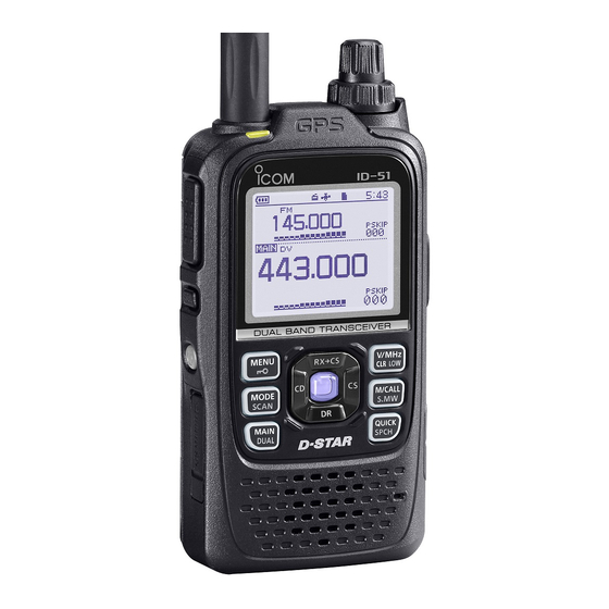
The photo shows
the ID-51E version.
Advertisement
Table of Contents

Related Manuals for Icom ID-51A


Summary of Contents for Icom ID-51A
- Page 1 BASIC INSTRUCTIONS VHF/UHF TRANSCEIVER ID-51A VHF/UHF TRANSCEIVER ID-51E This device complies with Part 15 of the FCC Rules. Operation is subject to the following two conditions: (1) this device may not cause harmful interference, and (2) this device must accept any interference received, including interference that may cause undesired operation.
-
Page 2: Features
Rapid charging is possible, and the charg- ❍ We thank you for making your ID-51A or ID-51E your radio of ing time period is approximately 3 hours choice, and hope you agree with Icom’s philosophy of “tech- with the supplied battery pack. -
Page 3: Explicit Definitions
* Not supplied, or the shape is different, depending on the transceiver version. IMPORTANT READ ALL INSTRUCTIONS carefully and completely before using the transceiver. SAVE THIS INSTRUCTION MANUAL— This in- struction manual contains basic operating instructions for the ID-51A/ID-51E. -
Page 4: About The Supplied Cd
ABOUT THE SUPPLIED CD D Starting the CD The following instructions and installers are included on the Insert the CD into the CD drive. • Double click “Menu.exe” on the CD. • Basic instructions • Depending on the PC setting, the Menu screen shown Instructions for the basic operations, the same as this man- below may be automatically displayed. -
Page 5: Important Notes
• GPS signals cannot pass through metal objects. When us- Depending on the combination of the operating band and ing the ID-51A or ID-51E inside a vehicle, you may not re- mode, the Dualwatch or Triple-watch operation may generate ceive GPS signals. We recommend you use it near a win- certain spurious signals, or noise may be heard. -
Page 6: Precautions
Icom radios or Icom chargers. Only Icom battery operate the transceiver with packs are tested and approved for use with Icom radios or an earphone, headphones or other audio accessories at high charged with Icom chargers. Using third-party or counterfeit volume levels. - Page 7 PRECAUTIONS CAUTION: DO NOT Place the unit in a secure place to avoid inadvertent use by use harsh solvents such as ben- children. zine or alcohol to clean the transceiver, because they can damage the transceiver’s surfaces. The BP-273 meets IPX4 requirements for splash resistance. DO NOT When it is connected, the transceiver corresponds to IPX4.
-
Page 8: Battery Cautions
Icom radios or Icom chargers. Only Icom battery modify the battery pack. This may cause heat generation, and packs are tested and approved for use with Icom radios or the battery may burst, emit smoke or catch fire. -
Page 9: D Charging Caution
0˚C to +40˚C (+32˚F to +104˚F). time, it must be detached from the radio after discharging. Icom recommends charging the battery at +25˚C (+77˚F). The You may use the battery until the battery indicator shows half- battery may heat up or rupture if charged out of the specified capacity, then keep it safely in a cool dry place at the following temperature range. -
Page 10: Table Of Contents
TABLE OF CONTENTS FOREWORD ................. i 2 STARTING INITIAL SETUP ...... 9–18 FEATURES ................i Attaching the Battery pack ..........9 ■ EXPLICIT DEFINITIONS ............ii Charging the battery pack .........10 ■ IMPORTANT ................. ii Inserting the microSD card ........10 ■ SUPPLIED ACCESSORIES .......... -
Page 11: Table Of Contents
TABLE OF CONTENTS Key Lock function ............37 7 RECORDING A qSO ■ Transmitting ...............38 ■ ONTO A SD CARD ......72–76 micro BC Radio operation ...........40 ■ About the microSD card ..........72 ■ Recording a QSO audio ..........73 ■ 5 MEMORY CHANNEL OPERATION ..41–42 Playing recorded audio ..........74 ■... -
Page 12: Unique Functions
UNIqUE FUNCTIONS This section introduces unique functions built into the ID- Auto Position Reply function 51A/E. • See the PDF type Advanced Instructions’s for more details. When you receive a call addressed to your own call sign, but are in a situation that makes it difficult to operate the trans- QSO Recording function ceiver, this function automatically replies with your own call sign and transmits your position. -
Page 13: Near Fm Repeater Search Function
UNIQUE FUNCTIONS Near FM Repeater search function Add-on functions for D-PRS You can enter FM repeater data D-PRS enables the transceiver to receive the Object, Item or using the DR function. Weather data in addition to position data. The function can find only FM re- With the D-PRS add-on functions, you can receive informa- peaters in your transceiver’s re- tion such as an event, traffic, emergency or weather while... -
Page 14: Panel Description
PANEL DESCRIPTION ■ Front, top and side panels e PTT SWITCH [PTT] (p. 38) Hold down to transmit, release to receive. For ID-51E only Push briefly and release, then hold down to transmit a 1750 Hz tone burst. r CD (RX CALL SIGN DISPLAY)/D-PAD (LEFT) KEY Function [CD]/D-pad() display (p. - Page 15 PANEL DESCRIPTION i MODE • SCAN KEY [MODE•SCAN] !3 EXTERNAL DC IN JACK [DC IN] ➥ Push to select the operating mode. (p. 34) Connects to the supplied BC-167SA/SD/SV wall char- ➥ • Selectable operating modes are AM, FM, FM-N or ger, to charge the attached battery pack.
- Page 16 Call channel mode. (p. 36) ➥ While in the DR screen, or with the Menu screen For ID-51A only or Quick Menu screen open, push to select a In the Call channel mode, push once to enter lower tier menu.
-
Page 17: Quick Menu
PANEL DESCRIPTION D Quick Menu VOLUME CONTROL [VOL] Rotate to adjust the audio volume level. (p. 11) In the Quick Menu, the selectable items differ, depending on the operating mode or function. The items shown below are CONTROL DIAL [DIAL] examples. -
Page 18: Function Display
PANEL DESCRIPTION ■ Function display q BATTERY ICON Shows the capacity of the attached battery pack in four ➥ r y u io !0 levels. • “ ” (battery icon) appears when the battery pack is attached. • “ ” appears when the battery pack must be charged. - Page 19 PANEL DESCRIPTION t DUPLEX ICON !1 TONE ICONS • While operating in the FM or FM-N mode: “DUP+” appears when plus duplex is selected, and “DUP–” appears when minus duplex is selected. “ TONE” appears while the Repeater Tone Encoder is ➥...
- Page 20 PANEL DESCRIPTION Function display (Continued) ■ !3 PRIORITY WATCH ICON Appears when Priority Watch is in use. r y u io !0 !4 WEATHER ALERT ICON Appears when the Weather alert function is ON. !5 ATTENUATOR ICON Appears when the attenuator is ON in the AIR band. !6 SKIP ICON “...
-
Page 21: Panel Description
PANEL DESCRIPTION !9 S/RF METER Shows the relative signal strength of the receive sig- ➥ nal. Shows the output power level of the transmit signal. ➥ (p. 38) @0 POWER ICONS (p. 39) “ SLO” appears when S-low power is selected. ➥... -
Page 22: Starting Initial Setup
STARTING INITIAL SETUP ■ Attaching the Battery pack Before starting D-STAR, the following steps are needed or Attach or detach the battery pack or battery case, as recommended. illustrated below. STEP 1 Attaching the Battery pack, and charging the bat- tery. -
Page 23: Charging The Battery Pack
STARTING INITIAL SETUP ■ Charging the battery pack ■ Inserting the microSD card Prior to using the transceiver for the first time, the battery Make sure the transceiver turns OFF. pack must be fully charged for optimum life and operation. Lift OFF the [micro SD] slot cover on the side panel. -
Page 24: Power On
■ Setting Date/Time Hold down [ ] for 1 second to turn ON power. The ID-51A/E has a built-in internal GPS receiver, and has a ➥ • After the opening message and power source voltage are dis- time correction function. The transceiver automatically sets played, the operating frequency appears. - Page 25 STARTING INITIAL SETUP D Receiving GPS data Check whether or not the GPS receiver is receiving your To prolong the battery life in the GPS mode position and time. To prolong the battery life while in the GPS is ON, manually The GPS icon blinks when searching for satellites.
-
Page 26: Enter Your Call Sign Into The Transceiver
STARTING INITIAL SETUP ■ Enter your call sign into the transceiver You can enter up to six MY call signs, in [MY1] through [MY6]. Displays the MY Call Sign edit screen t Push [QUICK] , and then Example: Enter “JA3YUA” as your own call sign into the MY push D-pad() to select “Edit.”... - Page 27 STARTING INITIAL SETUP Repeat steps y and u to enter your own call sign of up to 8 characters, including spaces. ( For example: First J, then A, then 3, then Y, then U, then A) Convenient! Push D-pad(Ent) to set the ✓...
-
Page 28: Register Your Call Sign At A Gateway Repeater
STARTING INITIAL SETUP ■ Register your call sign at a gateway repeater To use the Internet, you must register your call sign with a Access the call sign registration screen repeater that has a gateway, usually one near your home lo- Access the following URL to find the gateway repeater cation. - Page 29 STARTING INITIAL SETUP Register your call sign Register your D-Star equipment Follow the registration instructions on the registration Register your D-STAR equipment information. screen. Ask the gateway repeater administrator for details. When you receive a notification from the administrator, When your registration is complete, log out of your per- your call sign registration has been approved, but the sonal account, and start using the D-STAR network.
-
Page 30: Save Setting Data Onto A Microsd Card (Recommend)
STARTING INITIAL SETUP ■ Save setting data onto a microSD card (Recommend) Memory channels, item settings in the menu screen, and repeater lists can be saved on the microSD card. Saving data settings on the microSD card allows you to easily restore the transceiver to its previous settings, even if an all reset is performed. - Page 31 STARTING INITIAL SETUP D Save setting For your information ✓ Push D-pad( ) to select “<<New File>>,” and then push Data settings are saved in the “icf” file format that is used in D-pad(Ent). the CS-51PLUS cloning software. • The FILE NAME screen is displayed. The saved data on the microSD card can be copied onto a •...
-
Page 32: Menu Screen
MENU SCREEN Menu item selection ■ The Menu screen is used to program infrequently changed Push D-pad( ) to select values or function settings. “30min.” In addition to this page, see pages 20 through 30 for details of each items. NOTE: The Menu system is constructed in a tree structure. -
Page 33: Menu Items And Their Details
MENU SCREEN ■ Menu items and their details This topic describes the Menu items and their details. Scan DUP/TONE... Set scan options. Settings to access repeaters. Offset Freq Pause Timer Sets the frequency offset for duplex (repeater) operation. Selects the scan pause time. When receiving signals, the Repeater Tone scan pauses according to the scan pause timer. - Page 34 MENU SCREEN Menu items and their details ■ Root item “Scan” (Continued) Voice Recorder Voice Memo Set Voice recorder options. Set the TX/RX voice recording options. Record* QSO Recorder Starts recording the microphone audio. Set QSO recorder options. Play Files* <<REC Start>>* Plays or deletes the recorded audio.
- Page 35 MENU SCREEN <<Single TX>>* The transceiver transmits the recorded voice audio only Set GPS options. one time. GPS Set <<Repeat TX>>* GPS Select The transceiver repeatedly transmits the recorded voice Selects the GPS receiver that the transceiver receives its audio for a maximum of 10 minutes. position data from.
- Page 36 MENU SCREEN Menu items and their details ■ Root item “GPS” (Continued) GPS Alarm Symbol Set GPS alarm options. Selects a object station’s symbol to transmit. Alarm Select SSID Select the target for the GPS alarm function. Selects the APRS ®...
- Page 37 MENU SCREEN Call Sign My Station Set and display the DV mode call signs. Sets and stores your call sign to use in the DV mode. UR: CQCQCQ, R1: --------, R2: --------, MY: -------- My Call Sign Displays the operating call signs. Stores your call signs.
- Page 38 MENU SCREEN Menu items and their details ■ Root item “DV Set” (Continued) Auto Reply RX Call Sign Write Selects the Automatic Reply function. Turns the RX call sign automatic write function ON or OFF. DV Data TX This function is usable in any DV mode except the DR Selects manually or automatically to transmit data.
- Page 39 MENU SCREEN SPEECH QSO/RX Log Sets the Speech functions. Sets the QSO/RX History Log options. RX Call Sign SPEECH QSO Log Selects the RX call sign speech function option while ON, Selects whether or not to make a communication log on or turn it OFF.
- Page 40 MENU SCREEN Menu items and their details ■ Root item “Function” (Continued) Data Speed Remote MIC Key Selects the data transmission speed for low-speed com- The function assignments for keys on the optional HM- 75LS can be changed for simple remote control operation. munication, or between the [DATA] jack and external mod- During RX/Standby ules like a GPS receiver, and so on.
- Page 41 MENU SCREEN CI-V Baud Rate Reply Position Display Sets the CI-V code transfer speed. Selects whether or not to display the caller's position data CI-V Transceive when the data is included in the Auto Reply signal. Turns the CI-V Transceive function ON or OFF. DV RX Backlight Heterodyne Turns the DV RX Backlight function ON or OFF.
- Page 42 MENU SCREEN Menu items and their details ■ Root item “Display” (Continued) Rainfall Key-Touch Beep Selects the units to display the rainfall. Turns the confirmation beep tones when key is pushed, Wind Speed ON or OFF. Home CH Beep Selects the units to display the wind speed. Display Language Turns the Home CH Beep ON or OFF.
-
Page 43: Menu Screen
Export Clone Master Mode Selects to export the Your call sign, Repeater list, or GPS Sends the memory or setting data to other ID-51A/E. memory data in the CSV format file. The clone Master mode of the Transceiver to Transceiver. -
Page 44: Basic Operation
Example: MAIN band is FM-N mode. ■ Dualwatch operation SUB band is DV mode. Dualwatch operation simultaneously monitors two frequencies. The ID-51A/E has two independent receiver circuits, A band MAIN band and B band. Depending on the operating band or mode, the SUB band Appears when the audio signal is muted. -
Page 45: Main Band Selection
BASIC OPERATION D Dualwatch operation ON or OFF D MAIN band selection Hold down [DUAL] for 1 second to turn the dualwatch Push [MAIN] to alternately select upper band or lower ➥ ➥ operation ON or OFF. band as the MAIN band. •... -
Page 46: Selecting The Operating Band
BASIC OPERATION ■ Selecting the operating band ■ Selecting a tuning step The transceiver can receive the AIR, 144 MHz or 430 MHz Rotating [DIAL] changes the frequency in the selected tuning bands. steps. The VFO scan uses this step when searching for signals. q Push [V/MHz] to select The following tuning steps are selectable. -
Page 47: Selecting The Operating Mode
BASIC OPERATION ■ Selecting the operating mode ■ Setting a frequency Operating modes are determined by the modulation of the q When VFO mode is selected, push [V/MHz] to select radio signals. The transceiver has a total of four operating the 1 MHz or 10 MHz Quick Tuning function step, or turn modes, AM, FM, FM-N and DV. -
Page 48: Setting The Squelch Level
BASIC OPERATION ■ Setting the squelch level ■ Monitor function While holding down [SQL], rotate [DIAL] one click to dis- This function is used to listen to weak signals without disturb- play the current squelch level. ing the squelch setting, or having to open the squelch manu- While holding down [SQL], rotate [DIAL] to select the ally, even when mute functions such as the tone squelch are squelch level. -
Page 49: Selecting The Mode And The Dr Function
BASIC OPERATION Selecting the Mode and the DR function ■ Memory/Call channel/Weather channel* mode • VFO mode The VFO mode is used to set the desired frequency. In the VFO mode, push [M/CALL] to select the Mem- ory mode. • Memory mode •... -
Page 50: Key Lock Function
BASIC OPERATION ■ Key Lock function Selecting the Mode and the DR function (Continued) ■ Selecting the DR (D-STAR Repeater) function Activate to prevent accidental frequency changes and unnec- The DR (D-STAR Repeater) function is used for D-STAR repeater operation. With this function, you can easily select essary function access. -
Page 51: Transmitting
BASIC OPERATION ■ Transmitting R WARNING! NEVER transmit for long periods of time. CAUTION: Transmitting without an antenna will damage the During prolonged transmissions at high power or mid pow- transceiver. er, the transceiver radiates heat to protect itself from over- NOTE: To prevent interfering, hold down [SQL] to listen on heating. - Page 52 BASIC OPERATION D About transmit power levels ❍ When the external DC power cable (13.5 V DC) is con- nected or BP-271/BP-272 is attached. : 5 W (High)/2.5 W (Mid)/1.0 W (Low2)/ 0.5 W (Low1)/0.1 W (S-Low) (approximately) ❍ When the BP-273 is attached. : Approximately 0.1 W (S-LOW) (fixed) NOTE: When using the BP-273 battery case, “SLO,”...
-
Page 53: Bc Radio Operation
BASIC OPERATION BC Radio operation ■ D AM/FM radio mode selection D Turning ON the BC Radio Push [QUICK] Push [MODE] to select the AM or FM radio ➥ Push D-pad( ) to select mode. “<<BC Radio ON>>,” and FM mode then push D-pad(Ent). -
Page 54: Memory Channel Operation
MEMORY CHANNEL OPERATION ■ Memory channel programming The Memory mode is useful to quickly select often-used re- Rotate [DIAL] to select the peaters. channel 11. This section describes the basic channel programming. • Select Call channels (C0 to C3) to program into a call chan- See the Advanced Instructions for details. -
Page 55: Selecting The Memory Channel
MEMORY CHANNEL OPERATION ■ Selecting the Memory channel In the memory mode, you can select the programmend mem- ory channels by rotating [DIAL]. Example: Selecting the Memory channel 7 Push [M/CALL] one or more times to enter the Mem- Rotate [DIAL] to select channel 7. ory mode. -
Page 56: Features
● through the repeater ID-51A/E 1200 MHz (144/430 MHz) You can communicate with a 1200 MHz D-STAR station using the ID-51A/E! Easy call sign entry with the ● Repeater list or TX/RX History Easy Desti- nation (To) setting! Call Sign Capture key ●... -
Page 57: D-Star Introduction
D-STAR OPERATION Before starting D-STAR, the following steps are needed. STEP 1 Entering your call sign (MY) into the transceiver. STEP 2 Registering your call sign (MY) to a gateway repeater. IMPORTANT! STEP 3 Entering your D-STAR equipment into your registration form. You have completed the steps!! See pages 13 to 16 for details. -
Page 58: Ways To Communicate With The Dr Function
D-STAR OPERATION Ways to Communicate with the DR function ■ With the DR function, the transceiver has three ways to communicate, as shown below. Access repeater Simplex call Local area call Hamacho repeater Hamacho area To call another station not using a repeater. To call through your local area (access) repeater. -
Page 59: Making A Simplex Call
D-STAR OPERATION ■ Making a Simplex call You can make a transceiver to transceiver call (through no Push D-pad( ) to select “Re- repeater) in the DR screen. peater List,” and then push D-pad(Ent). NOTE: Depending on the transceiver's version, the fre- quencies may be different. -
Page 60: Accessing Repeaters
D-STAR OPERATION ■ Accessing repeaters Making a Simplex call (Continued) ■ This section describes how to check whether or not you can Hold down [PTT] to transmit access your local area repeater (Access repeater), and if your While holding down [PTT], signal is successfully sent to a destination repeater. - Page 61 D-STAR OPERATION Push D-pad( ) to select “Re- If the selected repeater name peater List,” and then push is displayed in “FROM” on the D-pad(Ent). DR screen, the access re- peater setting is completed. Completed Completed Push D-pad( ) to select the repeater group where your access repeater is listed, and NOTE: See page 60 for status indications after a repeater...
- Page 62 D-STAR OPERATION Accessing repeaters (Continued) ■ Select the Destination repeater (“TO”) Example: Your destination repeater is Hamacho/Japan in the Push D-pad( ) to select the repeater list. repeater group where your destination repeater is listed, Push D-pad( ) to select “TO” and then push D-pad(Ent).
-
Page 63: Using The Rx History
D-STAR OPERATION ■ Using the RX history Check whether you can access the repeater When a DV call is received, the call signs of the caller, the Hold down [PTT] for approxi- called station and the called station’s access repeater are mately 1 second to access stored in the RX history file. - Page 64 D-STAR OPERATION Using the RX history (Continued) ■ To display a received call sign Save the destination call sign into your call sign mem- ory from RX History Hold down for 1 second. Push D-pad( ) to select the • Displays the RX HISTORY screen. RX HISTORY record with the Caller station call sign that you want to save...
- Page 65 D-STAR OPERATION Push D-pad( ) to select the About text entry call sign that you want to save, • Push D-pad() to move the and then push D-pad(Ent). cursor backward or forward. • Example: “JM1ZLK” • While selecting a character, push [QUICK] to change The display changes to the...
- Page 66 D-STAR OPERATION Using the RX history (Continued) ■ After entering the name, push The saved call sign is displayed on D-pad(Ent). the YOUR CALL SIGN screen as a • Example: “TOM” selectable destination. Push D-pad( ) to select “<<Add Write>>,” and then push D-pad(Ent).
-
Page 67: Capturing A Call Sign
D-STAR OPERATION ■ Capturing a call sign After you receive a repeater’s signal, the calling station’s call Set the received call sign to the destination sign can be captured by touching the Call Sign Capture key Hold down for 1 second. ) for 1 second. -
Page 68: Making A Local Area Call
D-STAR OPERATION ■ Making a Local area call Capturing a call sign (Continued) ■ Hold down [PTT] to transmit A Local area call can be made when “Local CQ” is used to set “CQCQCQ” in “TO” (Destination). While holding down [PTT], speak at your normal voice What is a Local Area Call? ✓... - Page 69 D-STAR OPERATION Push D-pad( ) to select your Hold down [PTT] to transmit access repeater, and then While holding down [PTT], speak push D-pad(Ent). at your normal voice level. • Example: “Hirano” Set “TO” (Destination) Transmitting Push D-pad( ) to select “TO,” and then push D-pad(Ent).
-
Page 70: Making A Gateway Repeater Call
D-STAR OPERATION ■ Making a Gateway Repeater call A Gateway call can be made when a destination repeater is Push D-pad( ) to select your selected in “TO” (Destination). access repeater, and then push D-pad(Ent). What is a Gateway Repeater Call? ✓... -
Page 71: Calling An Individual Station
D-STAR OPERATION ■ Calling an individual station Push D-pad( ) to select the repeater group where your You can make a call to an individual station when the station destination repeater is listed, call sign is selected in “TO” (Destination). and then push D-pad(Ent). - Page 72 D-STAR OPERATION Calling an individual station (Continued) ■ Push D-pad( ) to select your Push D-pad( ) to select the access repeater, and then destination station, and then push D-pad(Ent). push D-pad(Ent). • Example: “Hirano430” • Example: “TOM” Set “TO” (Destination) Hold down [PTT] to transmit Push D-pad( ) to select “TO,”...
-
Page 73: Troubleshooting
D-STAR OPERATION ■ Troubleshooting To communicate through the repeater, your signal must access to the repeater. When your signal accesses your local repeater, but it is not sent to the destination repeater, the repeater replies with an status message. PROBLEM POSSIBLE CAUSE SOLUTION REF. - Page 74 D-STAR OPERATION Troubleshooting (Continued) ■ PROBLEM POSSIBLE CAUSE SOLUTION REF. After your call, the access repeat- • The call sign of the destination repeater is • Correctly set the destination repeater call sign. — er replies ‘RPT?’ and its call sign. wrong.
-
Page 75: Reflector Operation
D-STAR OPERATION ■ Reflector operation What is the reflector? Linking to a reflector A reflector is a special server connected to the internet and If your repeater is not currently linked to a reflector, or you running a version of dplus software. If the dplus software is want to change to another reflector, you can do so following installed on your access repeater, it provides various functions the steps below. - Page 76 D-STAR OPERATION Reflector operation ■ Linking to a reflector (Continued) Using the TX History Push D-pad( ) to select “Link to Reflector,” and then The TX History stores the up to 5 reflectors that your access push D-pad(Ent). repeater linked to before. Push D-pad( ) to select “Di- rect Input,”...
-
Page 77: Using A Reflector
D-STAR OPERATION Using a reflector Push D-pad( ) to select Hold down for 1 sec- “Link to Reflector,” and then ond. push D-pad(Ent). Push D-pad( ) to select “TO,” and then push D-pad(Ent). D-pad (Ent) (�) Push D-pad( ) to select Push D-pad( ) to select the “Reflector,”... -
Page 78: Unlinking A Reflector
D-STAR OPERATION Reflector operation (Continued) ■ Unlinking a reflector Before linking to another reflector, be sure to unlink the cur- rent reflector. Push D-pad( ) to select “Un- Hold down for 1 sec- link Reflector.” ond. Push D-pad( ) to select “TO,” and then push D-pad(Ent). - Page 79 D-STAR OPERATION Reflector Echo Testing You can transmit a short message, and after releasing [PTT], your message will be played back. It is a useful check of how well your signal is getting into the repeater, and you can use it to verify that your repeater is operating normally.
-
Page 80: Requesting Repeater Information
D-STAR OPERATION Reflector operation (Continued) ■ Requesting repeater information When you send the repeater information command, an ID message is sent back. Push D-pad( ) to select “Re- Hold down for 1 sec- peater Information.” ond. Push D-pad( ) to select “TO,” and then push D-pad(Ent). -
Page 81: Updating The Repeater List
• The displayed contents may differ. The latest setting files can be downloaded from the Icom website. Downloading the latest setting file (ICF file) q Access the following URL to download the latest data. - Page 82 PC. same place where the downloaded file is saved. • Icom recommends that you format all microSD cards to be used t Copy the ICF file (Example: “51P_USA_140820.icf”) in the with the ID-51A/E, even preformatted microSD cards for PCs or folder to the “Setting”...
- Page 83 D-STAR OPERATION Saving the current data is recommended before loading other data into the transceiver. Inserting the microSD card Updating the repeater list y Remove the microSD card from the PC, and insert the card into the transceiver’s slot. u Push [MENU] See pages 10, 75 and 76 for details of inserting and re- i Push D-pad() to select moving the microSD card.
-
Page 84: D-Star Operation
D-STAR OPERATION Updating the repeater list (Continued) ■ !0 Push D-pad() to select “Re- !4 Push D-pad() select peater List Only,” and then “YES,” then push D-pad(Ent) push D-pad(Ent). to start the file check. !1 Push D-pad(Ent) to select • While checking file, “CHECKING FILE”... -
Page 85: Recording A Qso Onto A Microsd Card
• When reading or writing data is impossible, the microSD • Icom recommends that you format all microSD cards to be card’s lifetime has ended. In this case, purchase a new used with the transceiver, even preformatted microSD cards one. -
Page 86: Recording A Qso Audio
RECORDING A QSO ONTO A microSD CARD ■ Recording a QSO audio NOTE: BC Radio audio cannot be recorded. stop recording Push [QUICK] to enter the Quick Menu screen. Push [QUICK] to enter Push D-pad( ) to select the Quick Menu screen. “<<REC Start>>.”... -
Page 87: Playing Recorded Audio
RECORDING A QSO ONTO A microSD CARD ■ Playing recorded audio Push D-pad( ) to select the q Push [MENU] to enter folder that contains the file the Menu screen. you want to play, and then Push D-pad( ) to select push D-pad(Ent). -
Page 88: Removing The Microsd Card
RECORDING A QSO ONTO A microSD CARD ■ Removing the microSD card Removing the microSD card Turn OFF the power. Lift OFF the [micro SD] slot cover on the side panel. Push in the microSD card until a click sounds, and then carefully pull it out. - Page 89 RECORDING A QSO ONTO A microSD CARD Removing the microSD card while the transceiver’s power is ON If removing the microSD card while the transceiver’s power is ON, by doing the following steps. When the unmounting is Push [MENU] completed, “Unmount is com- Push D-pad( ) to select “SD pleted.”...
-
Page 90: Gps Operation
GPS OPERATION ■ GPS operation ■ Checking your GPS position The ID-51A/E has a built-in internal GPS receiver. You can You can check your current position. check your current position and time. If you transmit while displaying the GPS position screen, the screen closes. - Page 91 GPS OPERATION e The first MY GPS position screen appears. (1/5) r Push [CLR] to close the GPS Position screen. MY Position MEM Position <Contents of the GPS Position screen> Latitude The top of the compass is North. Longitude Your course head- Grid Locator ing is Northwest.
-
Page 92: Gps Logger Function
GPS OPERATION ■ GPS Logger function Turning OFF the GPS Logger function The GPS Logger function allows you to store the GPS po- If you do not use this function, sition data (Latitude, Longitude, Altitude, Positioning state, turn OFF the function as follow- Course, Speed and Date) onto a microSD card, as a route. -
Page 93: Resetting
RESETTING ■ Resetting The display may occasionally display erroneous information. A Partial reset resets operating settings to their default values This may be caused externally by static electricity or by other (VFO frequency, VFO settings, menu contents) without clear- factors. If this problem occurs, turn OFF power. After waiting ing the items below: a few seconds, turn ON power again. -
Page 94: Information
Latvia • Consult the dealer or an experienced radio/TV technician for help. CAUTION: Changes or modifications to this device, not ex- pressly approved by Icom Inc., could void your authority to operate this device under FCC regulations. -
Page 95: Index
INDEX Communication example Gateway Repeater call ..........57 About the microSD card ........... 72 Local area call .............. 55 Accessing repeaters ............47 Simplex call ..............46 AM/FM radio mode selection ..........40 Country code list ............... 81 Audio volume ..............11 Auto Position Reply function .......... - Page 96 INDEX FCC information ............... 81 Main band selection ............32 Features ................i Making a Call Foreword ................i Gateway Repeater call ..........57 Formatting the microSD card ..........17 Local area call .............. 55 Front, top and side panels ..........1 Simplex call ..............
-
Page 97: Index
INDEX QSO Recording function ............ xi Table of contents ............... ix Recording a QSO audio ..........73 Time Recording a QSO onto a microSD card ......72 Setting Date/Time ............11 Stop recording .............. 73 TSQL (Tone squelch) Quick Menu ................ 4 Function ON .............. -
Page 98: Index For Menu Items
INDEX FOR MENU ITEMS Active Band ..............[Function>] 27 Call Sign ................[Root] 24 Alarm Area (Group) ........[GPS>GPS Alarm>] 23 Charging (Power ON) ..........[Function>] 28 Alarm Area (RX/Memory) ......[GPS>GPS Alarm>] 23 CI-V .................[Function>] 27 Alarm Select ..........[GPS>GPS Alarm>] 23 CI-V Address ............ [Function>CI-V>] 27 All Reset ............ - Page 99 INDEX FOR MENU ITEMS DUP/TONE................. [Root] 20 GPS Message ....[GPS>GPS TX Mode>NMEA (DV-G)] 23 During RX/Standby ....... [Function>Remote MIC Key>] 27 GPS Out (To DATA jack) ........[GPS>GPS Set>] 22 During TX ........[Function>Remote MIC Key>] 27 GPS Position ..............[GPS>] 22 DV Auto Detect .............
- Page 100 INDEX FOR MENU ITEMS Record Interval ........... [GPS>GPS Logger>] 23 <<New File>> ........[SD Card>Save Setting>] 30 Recorder Set ....... [Voice Memo>QSO Recoder>] 21 NMEA (DV-G) ..........[GPS>GPS TX Mode>] 23 Recorder Set ......[Voice Memo>Voice Recoder>] 21 Record Sentence ........[GPS>GPS Logger>] 23 Offset Freq .............
-
Page 101: Index For Menu Items
INDEX FOR MENU ITEMS SD Card Info ...............[SD Card>] 30 Separator/Decimal ......[QSO/RX Log>CSV Format>] 26 Unmount ..............[SD Card>] 30 Separator/Decimal ..[SD Card>Import/Export/CSV Format>] 30 Unproto Address ....[GPS>GPS TX Mode>D-PRS (DV-A)] 23 <<Single TX>> ............[Voice TX>] 22 ................ [Call Sign>] 24 Skip Time ....[Voice Memo>QSO Recoder>Player Set>] 21 UTC Offset .............. -
Page 102: Specifications
±5.0 kHz (FM wide: approx.) • Power supply: 10.0–16.0 V DC for external DC ±2.5 kHz (FM narrow: approx.) power, or specified Icom’s battery • Occupied bandwidth: Less than 6.0 kHz (DV) pack • Spurious emissions: Less than –60 dBc at High/Mid. -
Page 103: Specifications
SPECIFICATIONS Receiver ■ • Receive system: Double-conversion superhetero- • Audio output power (at 10% distortion): More than 0.4 W with a 16 Ω load dyne Internal speaker More than 0.2 W with a 8 Ω load • Intermediate frequencies: External speaker A Band 46.35 MHz (1st IF) •... - Page 104 #52 Europe-05 ■ GB ■ IS ■ LI ■ NO ■ CH ■ BG ■ RO ■ TR ■ HR A-7175H-1EX-q Printed in Japan 2014 Icom Inc. © 1-1-32 Kamiminami, Hirano-ku, Osaka 547-0003, Japan Printed on recycled paper with soy ink.