
Related Manuals for Kenwood TM-271


Summary of Contents for Kenwood TM-271
- Page 1 INSTRUCTION MANUAL 144 MHz FM TRANSCEIVER VHF FM TRANSCEIVER TM-271A 144 MHz FM TRANSCEIVER TM-271E TM-271 MENU © B62-1804-00 (K,E,M2,M3,M4) 09 08 07 06 05 04 03 02 01 00...
- Page 2 This transceiver is no exception. As you learn how to use this transceiver, you will find that KENWOOD is pursuing “user friendliness”. For example, each time you change the Menu No. in Menu mode, you will see a text message on the display that lets you know what you are configuring.
- Page 3 • Do not transmit with high output power for extended periods; the transceiver may overheat. • Do not modify the transceiver unless instructed by this manual or other KENWOOD documentation. • Do not expose the transceiver to long periods of direct sunlight nor place it close to heating appliances.
-
Page 4: Table Of Contents
SUPPLIED ACCESSORIES ... 1 WRITING CONVENTIONS FOLLOWED IN THIS MANUAL ... 1 CHAPTER PREPARATION MOBILE INSTALLATION ... 2 DC POWER CABLE CONNECTION ... 3 Mobile Operation ... 3 Fixed Station Operation ... 4 Replacing Fuses ... 5 ANTENNA CONNECTION ... 5 ACCESSORY CONNECTIONS ... - Page 5 RECALLING A MEMORY CHANNEL ... 30 ... 30 SING THE UNING ONTROL ... 31 SING THE ICROPHONE EYPAD CLEARING A MEMORY CHANNEL ... 31 NAMING A MEMORY CHANNEL ... 32 MEMORY CHANNEL TRANSFER ... 33 \ VFO T ... 33 EMORY RANSFER ...
- Page 6 FREQUENCY STEP SIZE ... 56 DISPLAY BACKLIGHT ... 57 ... 57 ERMANENT ACKLIGHT ... 57 UTOMATIC ACKLIGHT LOCK FUNCTION ... 58 DATA COMMUNICATION SPEED ... 58 TUNE ENABLE ... 58 MICROPHONE PF KEYS (K EYPAD NARROW BAND FM OPERATION ... 60 POWER-ON MESSAGE ...
-
Page 7: Supplied Accessories
SUPPLIED ACCESSORIES After carefully unpacking the transceiver, identify the items listed in the table below. We recommend you keep the box and packaging for shipping. A market area code (K, E, M2, M3, or M4) can be found on the label attached to the package box. WRITING CONVENTIONS FOLLOWED IN THIS MANUAL The writing conventions described below have been followed to simplify instructions and avoid unnecessary... -
Page 8: Preparation
MOBILE INSTALLATION To install the transceiver, select a safe, convenient location inside your vehicle that minimizes danger to your passengers and yourself while the vehicle is in motion. Consider installing the unit at an appropriate position so that knees or legs will not strike it during sudden braking of your vehicle. -
Page 9: Dc Power Cable Connection
DC POWER CABLE CONNECTION Locate the power input connector as close to the transceiver as possible. OBILE PERATION The vehicle battery must have a nominal rating of 12 V. Never connect the transceiver to a 24 V battery. Be sure to use a 12 V vehicle battery that has sufficient current capacity. -
Page 10: Fixed Station Operation
IXED TATION PERATION In order to use this transceiver for fixed station operation, you will need a separate 13.8 V DC power supply (not included). The recommended current capacity of your power supply is 12 A. 1 Connect the DC power cable to the regulated DC power supply and ensure that the polarities are correct (Red: positive, Black: negative). -
Page 11: Replacing Fuses
After the problem is resolved, replace the fuse. If newly installed fuses continue to blow, disconnect the power cable and contact your authorized KENWOOD dealer or an authorized KENWOOD service center for assistance. e i l Only use fuses of the specified type and rating; otherwise the transceiver could be damaged. -
Page 12: Accessory Connections
To utilize the optional MCP-1A software, you must first connect the transceiver to your PC using an optional. Programming Cable (via the microphone jack). The MCP-1A is free downloadable software available from KENWOOD at the following URL: http://www.kenwood.com/i/products/info/amateur.html Note: Ask your dealer about purchasing a Programming Cable. -
Page 13: Connecting To Acquainted Tnc
CONNECTING TO A TNC (E M ARKET To connect an external TNC to the transceiver, use an optional PG-5A cable. The DATA connector on the rear of the transceiver mates with the 6-pin mini-DIN plug on this cable. • • e l i •... -
Page 14: Your First Qso
If you encounter problems or there is something you would like to know more, read the detailed explanations given later in this manual. TM-271 MENU YOUR FIRST QSO YOUR FIRST QSO q Press [ ] (Power) briefly to switch the transceiver power ON. -
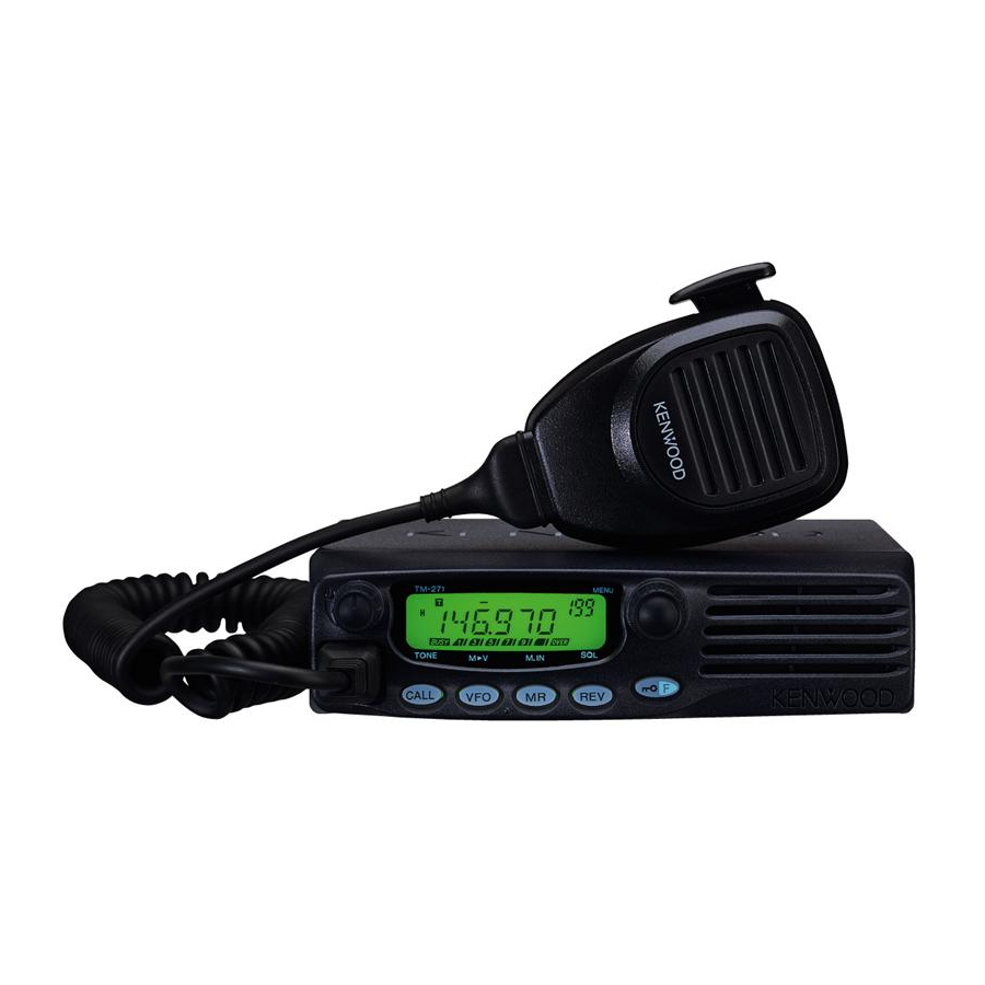
Page 15: Front Panel
Note: This section describes only the main functions of the front panel controls. Explanations for functions not described here are provided in the appropriate sections of this instruction manual. TM-271 MENU q q q q q (Power) switch/ Volume control Press to switch the transceiver power ON or OFF {page 14}. -
Page 16: Display
In MR Mode, press [F] then press [VFO] to transfer the contents of the selected Memory Channel to the VFO {page 33}. t t t t t MR key Press to enter Memory Recall Mode {page 30}. In this mode, you can change memory channels using the Tuning control or Mic [UP]/[DWN]. - Page 17 Appears when the Automatic Simplex Check (ASC) function is activated {page 26}. Appears when the Priority Scan function is activated {page 43}. Appears when the Weather Alert function is activated {page 36}. (K market models only.) Appears when narrow FM Mode is selected {page 60}. Displays the frequencies, Menu settings, Memory name and other information.
-
Page 18: Rear Panel
REAR PANEL q q q q q Antenna connector Connect an external antenna {page 5} here. When making test transmissions, connect a dummy load in place of the antenna. The antenna system or load should have an impedance of 50 Ω. Note: E market models use an N-type antenna connector while other models use an M-type (SO-239) connector. -
Page 19: Mic Keypad Direct Entry
r r r r r CALL/A key Identical to the front panel CALL key. This key can be reprogrammed if desired {page 59}. Press and hold Mic [PTT], then press [CALL/A] to transmit A. t t t t t VFO/B key Identical to the front panel VFO key. -
Page 20: Chapter 4 Operating Basics
SWITCHING THE POWER ON/OFF 1 Press [ ] (Power) to switch the transceiver power ON. • A high pitched double beep sounds and a Power-on message {page 60} appears briefly, followed by the frequency and other indicators. 2 To switch the transceiver OFF, press [ •... -
Page 21: Transmitting
TRANSMITTING 1 To transmit, hold the microphone approximately 5 cm (2 inches) from your mouth, then press and hold Mic [PTT] and speak into the microphone in your normal tone of voice. • “ ” and the RF Power meter appears. The RF Power meter shows the relative transmit output power •... -
Page 22: Mhz Mode
If the desired operating frequency is far away from the current frequency, it is quicker to use the MHz Tuning Mode. To adjust the MHz digit: 1 While in VFO or Call Mode, press [MENU]. • The MHz digit blinks. 2 Turn the Tuning control to select the desired MHz value. - Page 23 Example 1 To enter 145.750 MHz: Key in Display [Enter] – – – – – – [1], [4], [5] 1 4 5. – – – [7], [5], [0] 1 4 5. 7 5 0 Example 2 To enter 145.000 MHz: Key in Display [Enter]...
-
Page 24: Chapter 5 Menu Setup
WHAT IS A MENU? Many functions on this transceiver are selected or configured via a software-controlled Menu rather than through the physical controls of the transceiver. Once you become familiar with the Menu system, you will appreciate its versatility. You can customize the various timings, settings, and programming functions on this transceiver to meet your needs without using many controls and switches. -
Page 25: Menu Function List
MENU FUNCTION LIST t f i c i t y t i c i t i t c – y t i –... - Page 26 t f i c i t i t c l a i s t i – –...
- Page 27 c i t TXP (Transmission power) cannot be adjusted on M4 market models. It is fixed at “H” (High: 25 W). WXA (Weather Alert) is available only for K market models. i t c —...
-
Page 28: Offset Programming Flow
Repeaters, which are often installed and maintained by radio clubs, are usually located on mountain tops or other elevated locations. They generally operate at higher ERP (Effective Radiated Power) than a typical station. This combination of elevation and high ERP allows communications over much greater distances than communicating without using repeaters. -
Page 29: Programming An Offset
PROGRAMMING AN OFFSET You must first select an amateur radio repeater downlink frequency as described in “S ELECTING AN ”. REQUENCY ELECTING AN FFSET IRECTION Select whether the transmit frequency will be higher (+) or lower (–) than the receive frequency. 1 Press [F], [MENU] and turn the Tuning control to select Menu No. -
Page 30: Activating The Tone Function
CTIVATING THE UNCTION To activate Tone, press [F], [CALL]. • As you press [F], [CALL], the selection cycles as follows: “OFF” ➞ “TONE” ➞ “CTCSS” ➞ “DCS” ➞ “OFF”. • “T” appears on the upper part of display, indicating that the Tone function is activated. -
Page 31: Automatic Repeater Offset
AUTOMATIC REPEATER OFFSET This function automatically selects an offset direction, according to the frequency on the VHF band. The transceiver is programmed for an offset direction as shown below. To obtain an up-to-date band plan for repeater offset direction, contact your national Amateur Radio association. -
Page 32: Reverse Function
REVERSE FUNCTION The reverse function exchanges a separate reception and transmission frequency. So, while using a repeater, you can manually check the strength of a signal that you receive directly from the other station. If the station’s signal is strong, both stations should move to a simplex frequency and free up the repeater. -
Page 33: Tone Frequency Id Scan
Note: ◆ Pressing [PTT] causes the “ ” icon to quit blinking. ◆ ASC can be activated while operating in Simplex Mode. However, it does not change the Transmission/Reception frequencies. ◆ ASC does not function while scanning. ◆ Activating ASC while using Reverse switches Reverse OFF. ◆... -
Page 34: Chapter 7 Memory Channels
In Memory Channels, you can store frequencies and related data that you frequently use so that you do not need to reprogram that data every time. You can quickly recall a programmed channel through simple operation. A total of 200 Memory Channels (100 when using the Memory Name function) are available for storing frequencies, modes, and other operating conditions. -
Page 35: Storing Simplex Frequencies Or Standard Repeater Frequencies
The data listed below can be stored in each Memory Channel: t f i Yes: Can be stored in memory. N/A: Cannot be stored in memory. Note: ◆ Memory Channel Lockout cannot be set to the Program Scan Memory (L0/U0 ~ L2/U2), the Priority Channel (Pr), or the Weather Alert Channel (AL). -
Page 36: Storing Odd-Split Repeater Frequencies
• Memory Channel numbers L0/U0 ~ L2/U2 {page 40}, Pr {page 43}, and AL (Weather Alert) {page 36} (K market models only) are reserved for other functions. 5 Turn the Tuning control or press Mic [UP]/[DWN] to select the Memory Channel in which you want to store the data. -
Page 37: Using The Microphone Keypad
SING THE ICROPHONE EYPAD You can also recall a Memory Channel by entering a desired Memory Channel number with the microphone keypad. 1 Press [MR] to enter Memory Recall mode. 2 Press the microphone key assigned the ENTER function. 3 Enter the channel number using the microphone keypad. -
Page 38: Naming A Memory Channel
NAMING A MEMORY CHANNEL You can name Memory Channels using up to 6 alphanumeric characters. When you recall a named Memory Channel, its name appears on the display in place of the stored frequency. Names can be call signs, repeater names, cities, names of people, etc. In order to use the Memory Name function, the Memory Channel capacity must be set to 100 channels. -
Page 39: Memory Channel Transfer
MEMORY CHANNEL TRANSFER \ VFO T EMORY RANSFER After retrieving frequencies and associated data from Memory Recall Mode, you can copy the data to the VFO. This function is useful, for example, when the frequency you want to monitor is near the frequency stored in a Memory Channel. - Page 40 The tables below illustrate how data is transferred between Memory Channels. When “100” is selected in Menu No.15 (M.CH). The AL Channel is available for K market models only. Note: ◆ When transferring an odd-split channel, the Reverse status, Offset direction, and Offset frequency are not transferred {pages 23, 26}.
-
Page 41: Call Channel
CALL CHANNEL Call Channel default settings: • On K and M market models, pressing [CALL] changes the transceiver to the Call Channel. • On E market models, pressing [CALL] causes the transceiver to transmit a 1750 Hz tone {page 25}. The Call Channel can be recalled instantly no matter what frequency the transceiver is operating on. -
Page 42: Weather Alert (K Market Models Only )
Note: ◆ When you recall an odd-split Call Channel, “+” and “–” appear on the display. ◆ Transmit offset status and Reverse status are not stored in an odd-split Call Channel. WEATHER ALERT (K M ARKET Any of the NOAA Weather Radio channels can be programmed to the AL memory channel of the transceiver. -
Page 43: Channel Display
4 Press any key other than [MENU] to exit Menu Mode. • The transceiver automatically changes to the AL channel. • The Tone, CTCSS, and DCS functions cannot be configured to the AL channel. • Priority Scan is set to OFF automatically when the Weather Alert function is turned ON. - Page 44 While in Channel Display mode, you cannot activate the following functions: • VFO Mode • VFO Scan • Call/VFO Scan • MHz Scan • Scan Direction • Memory Store • Memory to VFO Transfer • Memory to Memory Transfer • Clear Memory Channel •...
-
Page 45: Chapter 8 Scan
Scan is a useful function for hands-off monitoring of your favorite frequencies. By becoming comfortable with all types of scan, you will increase your operating efficiency. This transceiver provides the following types of scans. - l l l l a l l a y t i y t i... -
Page 46: Normal Scan
NORMAL SCAN When you are operating the transceiver in VFO Mode, 3 types of scanning are available: Band Scan, Program Scan, and MHz Scan. The transceiver scans the entire band of the frequency you selected. For example, if you are operating and receiving at 144.525 MHz, it scans all the frequencies available for the VHF band. -
Page 47: Mhz Scan
7 Turn the Tuning control or press Mic [UP]/[DWN] to select a matching Memory Channel from U0 ~ U2. • For example, if you have selected “L0” in step 3, select Memory Channel “U0”. 8 Press [MR] to store the end frequency in the Memory Channel. -
Page 48: Memory Scan
MEMORY SCAN Memory Scan monitors Memory Channels in which you have stored frequencies. HANNEL The transceiver scans all of the Memory Channels in which you have stored frequencies. 1 Press [MR] (1s). • Scan starts from the last Memory Channel number and ascends up through the channel numbers (default). -
Page 49: Call Scan
CALL SCAN You can alternate between monitoring the Call Channel and the current operating frequency. 1 Select the frequency (in VFO or Memory Recall Mode) you want to monitor. • In VFO Mode, turn the Tuning control or press Mic [UP]/ [DWN] to select the desired frequency. -
Page 50: Using Priority Scan
SING RIORITY 1 Press [F], [MENU] and turn the Tuning control to select Menu No. 12 (PRI). 2 Press [MENU] and turn the Tuning control to select “ON” or “OFF” (default). 3 Press [MENU] to store the setting or any other key to cancel. -
Page 51: Scan Resume Method
SCAN RESUME METHOD The transceiver stops scanning at the frequency (or Memory Channel) where a signal is detected. It then continues or stops scanning according to which Resume Mode you have selected. • Time-Operated Mode (default) The transceiver remains on a busy frequency (or Memory Channel) for approximately 5 seconds, then continues to scan even if the signal is still present. -
Page 52: Chapter 9 Selective Call
These Selective Calls allow you to ignore (not hear) unwanted calls from other persons who are using the same frequency. The transceiver unmutes only when it receives a signal having the same CTCSS tone or DCS code. TM-271 CTCSS freq.: 82.5 Hz SELECTIVE CALL Note: CTCSS and DCS do not cause your conversation to be private or scrambled. -
Page 53: Selecting Actcss Frequency
CTCSS F ELECTING A REQUENCY 1 Press [F], [MENU] and turn the Tuning control or press Mic [UP]/[DWN] to select Menu No. 3 (CT). • The current CTCSS frequency appears. 2 Press [MENU] and turn the Tuning control to select your desired CTCSS frequency. -
Page 54: Dcs
• While scanning, the decimal point of the CTCSS frequency blinks. • To reverse the scan direction, turn the Tuning control or press Mic [UP]/[DWN]. • To quit the function, press any key. • When a CTCSS frequency is identified, the identified frequency appears and blinks. -
Page 55: Dcs Code Id Scan
• The available DCS codes are shown in the following table. 3 Press [MENU] to store the new code or any other key to cancel. 4 Press any key other than [MENU] to exit Menu Mode. DCS C ID S This function scans through all DCS codes to identify the incoming DCS code on the received signal. -
Page 56: Chapter 10 Dual Tone Multi-Frequency (Dtmf) Functions
DUAL TONE MULTI-FREQUENCY (DTMF) FUNCTIONS This transceiver provides you with 10 dedicated DTMF Memory Channels. You can store a DTMF number (16 digits max.) in each of these channels to recall later for speed dialing. Many repeaters in the U.S.A. and Canada offer a service called Autopatch. -
Page 57: Dtmf Tx Hold
DTMF TX H This function causes the transceiver to remain in transmission mode for 2 seconds after you release each key. So, you can release Mic [PTT] while sending DTMF tones. 1 Press [F], [MENU] and turn the Tuning control to select Menu No. -
Page 58: Confirming Stored Dtmf Numbers
6 Repeat steps 4 and 5 to enter up to 16 digits. 7 Press [MENU] to complete the entry. • Press any key other than [MR], [VFO], [F], and [MENU] to cancel the entry. • To complete an entry of less than 16 digits, press [MENU] two times. -
Page 59: Adjusting The Pause Duration
DJUSTING THE AUSE URATION You can change the pause duration (a space digit) stored in Memory Channels. The default setting is 500 milliseconds. 1 Press [F], [MENU] and turn the Tuning control to select Menu No. 31 (PA). 2 Press [MENU] and turn the Tuning control to select 100, 250, 500 (default), 750, 1000, 1500, or 2000 ms. -
Page 60: Chapter 11 Auxiliary Functions
APO (AUTO POWER OFF) The transceiver switches OFF automatically if no keys or controls are pressed or adjusted for the selected duration. One minute before the transceiver switches OFF, warning beeps sound for a few seconds and “APO” blinks. You can select the APO time from OFF (disable), 30, 60, 90, 120, or 180 minutes. -
Page 61: Squelch Hang Time
1 Press [F], [MENU] and turn the Tuning control to select Menu No. 8 (SSQ). 2 Press [MENU] and turn the Tuning control to select “ON” or “OFF” (default). 3 Press [MENU] to store the setting. • The S-meter setting segments appear. 4 Press any key other than [MENU] to exit Menu Mode. -
Page 62: Busy Channel Lockout
3 Press [MENU] to store the setting or any other key to cancel. 4 Press any key other than [MENU] to exit Menu Mode. The transceiver generates the following warning beeps even if the Beep function is turned OFF. • APO warning beeps {page 54} •... -
Page 63: Display Backlight
The default step size for each model is as follows: Note: The market code is printed on the barcode label of the carton box. DISPLAY BACKLIGHT You can manually change the display brightness to match the lighting conditions where you are operating the transceiver. -
Page 64: Lock Function
LOCK FUNCTION The lock function disables most of the keys to prevent you from accidentally activating a function. Transceiver Lock is suitable for a typical mobile installation where you select most operations using the microphone. 1 Press [F] (1s). • “ ”... -
Page 65: Microphone Pf Keys (Keypad Models Only )
3 Press [MENU] to store the setting or any other key to cancel. 4 Press any key other than [MENU] to exit Menu Mode. MICROPHONE PF KEYS (K EYPAD You can access many transceiver settings without using transceiver keys or controls. Microphone keys PF/D, MR/C, VFO/B, and CALL/A are programmable with transceiver functions. -
Page 66: Narrow Band Fm Operation
• SHIFT: Shift function ON/OFF • LOW: Select transmission power • BRIGHT: Adjust display backlight • LOCK: Transceiver Lock function ON/OFF (must be held down for 1 second to activate) • TONE: Selection for Tone/ Selective Call • STEP: Select the frequency step size Note: Rather than entering Menu Mode and selecting PF1 ~ PF4, you can simply press and hold the PF key you want to program, then turn the transceiver power ON. -
Page 67: Programmable Vfo
3 Turn the Tuning control to select a character. • You can enter the following alphanumeric characters: 0 ~ 9, A ~ Z, – (hyphen), / (slash), and a space. • Rather than using the Tuning control, you can use the Mic keypad (keypad models only) to enter alphanumeric characters {page 64}. -
Page 68: Time-Out Timer
TIME-OUT TIMER The Time-out Timer limits the time of each transmission to a maximum of 3, 5, or 10 (default) minutes. Just before the transceiver stops the transmission, a warning beep sounds. This function is necessary to protect the transceiver from thermal damage and can therefore not be turned OFF. -
Page 69: Chapter 12 Microphone Control
You can change numerous transceiver settings by operating the Mic DTMF keys. The following table shows what function is switched ON and OFF or which setting is changed by pressing the DTMF keys in the appropriate mode of operation. MICROPHONE CONTROL r i f t i g r i f... -
Page 70: Mic Lock
DTMF tones are not transmitted in TX Mode if the DTMF Lock function is ON. When transmitting a stored DTMF number, press Mic [PTT]+Mic [PF/D], release Mic [PF/D], then press a Memory Channel number from 0 to 9. To transmit the “D”... -
Page 71: Chapter 13 Optional Accessories
Data Cable (E market only) MC-60A Stand Microphone (MJ-88 required) MCP-1A Memory Control Program (Free Software) The MCP-1A can be downloaded at: http://www.kenwood.com/i/ products/info/amateur.html Programming Cable Ask your dealer about purchasing a Programming Cable. MJ-88 Modular to 8-pin Microphone Plug... -
Page 72: Troubleshooting
TROUBLESHOOTING You may return this product for service to the authorized KENWOOD dealer from whom you purchased it, or any authorized KENWOOD service center. A copy of the service report will be returned with the transceiver. Please do not send subassemblies or printed circuit boards;... -
Page 73: Cleaning
Note: ◆ Record the date of purchase, serial number and dealer from whom this product was purchased. ◆ For your own information, retain a written record of any maintenance performed on this product. ◆ When claiming warranty service, please include a photocopy of the bill of sale, or other proof-of-purchase showing the date of sale. -
Page 74: Vfo Reset
Full Reset Method 2: 1 Press [F], [MENU] and turn the Tuning control to select Menu No. 99 (RESET). 2 Press [MENU] and turn the Tuning control to select “FULL”. 3 Press [MENU]. • “SURE ?” appears. • Press any key other than [MENU] to cancel. 4 Press [MENU] to reset the transceiver. -
Page 75: Troubleshooting
TROUBLESHOOTING The problems described in the following tables are commonly encountered operational malfunctions. These types of difficulties are usually caused by improper hook-up, accidental incorrect control settings, or operator error due to incomplete programming. These problems are usually not caused by circuit failure. Please review these tables and the appropriate section(s) of this instruction manual before assuming your transceiver is defective. - Page 76 . s l o l l t t i i t c i t c . s l c t i l i t c i l “ t . ” t i x t t i —...
-
Page 77: Specifications
Specifications are subject to change without notice due to advancements in technology. l i b y t i – ( SPECIFICATIONS – – ( v i t : s l : s l " " "... - Page 78 v i t y t i v i t y t i – ( v i t y t i – ( v i t y t i Ω t t i : s l : s l – 8 Ω...
-
Page 79: Index
1750 Hz ... 25 Confirming a Stored Number ... 52 Accessories Lock ... 53 Optional ... 65 Manual Dialing ... 50 Supplied ... 1 Monitor ... 50 All-Channel Scan ... 42 Pause Duration ... 53 Automatic Power Off ... 54 Storing in Memory ...