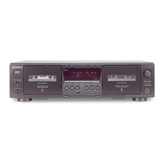
Sony TC-WE475 Service Manual
Stereo cassette deck
Hide thumbs
Also See for TC-WE475:
- Service manual (66 pages) ,
- Operating instructions manual (24 pages) ,
- Specifications (2 pages)
Table of Contents
Advertisement
QQ
3 7 63 1515 0
SERVICE MANUAL
Ver 1.0 2001.04
Dolby noise reduction extension manufactured under license
from Dolby Laboratories Licensing Corporation.
HX Pro originated by Bang & Olufsen. "DOLBY", the double-D
symbol ; and "HX PRO" are trademarks of Dolby Laboratories
Licensing Corporation.
TE
L 13942296513
System
Fast-winding time
Approx.100 sec. (with Sony C-60 cassette)
Signal-to-noise ratio (at peak level and weighted with Dolby
NR off)
55 dB, using Sony TYPE I cassette
57 dB, using Sony TYPE II cassette
58 dB, using Sony TYPE IV cassette
S/N ratio improvement
With Dolby B NR on:
Approx. 5 dB at 1 kHz, 10 dB at 5 kHz
With Dolby C NR on:
Approx. 15 dB at 500 Hz, 20 dB at 1 kHz
Harmonic distortion
0.4% (using Sony TYPE Icassette):
160 nWb/m 315 Hz, 3rd H.D.)
1.8% (using Sony TYPE IV cassette):
250 nWb/m 315 Hz, 3rd H.D.)
Frequency response (DOLBY NR OFF)
30-16,000 Hz (±3 dB, IEC), 20-17,000 Hz
(±6 dB), using Sony TYPE I cassette
30-17,000 Hz (±3 dB, IEC), 20-18,000 Hz
(±6 dB), using Sony TYPE II cassette
30-19,000 Hz (±3 dB, IEC), 20-20,000 Hz
(±6 dB), 30-13,000 Hz (±3 dB, –4dB recording),
using Sony TYPE IV cassette
www
.
Sony Corporation
9-873-893-11
Home Audio Company
2001D0900-1
© 2001. 4
Shinagawa Tec Service Manual Production Group
http://www.xiaoyu163.com
x
ao
u163
y
i
http://www.xiaoyu163.com
TC-WE475
2 9
8
Model Name Using Similar Mechanism
Transport Mechanism Type
Q Q
3
6 7
1 3
1 5
SPECIFICATIONS
Wow and flutter
±0.15% W. Peak (IEC)
0.1% W. RMS (NAB)
±0.2% W. Peak (DIN)
Variable pitch range
Approx. –30 to +30 %
Inputs
Line inputs (phono jacks)
sensitivity 0.16 V, input impedance 47 kilohms
Outputs
Line outputs (phono jacks)
rated output level 0.5 V at a load impedance of
47 kilohms, load impedance over 10 kilohms
Headphones (stereo phone jack)
output level 0.25 mW at a load impedance of
32 ohms
STEREO CASSETTE DECK
co
.
9 4
2 8
US Model
Canadian Model
AEP Model
UK Model
E Model
Australian Model
TC-WE435
DECK A
TCM-230ASR41A
DECK B
TCM-230ASR41B
0 5
8
2 9
9 4
2 8
— Continued on next page —
m
9 9
9 9
Advertisement
Table of Contents

Related Manuals for Sony TC-WE475


Summary of Contents for Sony TC-WE475
- Page 1 Signal-to-noise ratio (at peak level and weighted with Dolby ±0.2% W. Peak (DIN) NR off) Variable pitch range 55 dB, using Sony TYPE I cassette Approx. –30 to +30 % 57 dB, using Sony TYPE II cassette 58 dB, using Sony TYPE IV cassette...
- Page 2 LES COMPOSANTS IDENTIFIÉS PAR UNE MARQUE 0 SUR LES DIAGRAMMES SCHÉMATIQUES ET LA LISTE DES PIÈCES SONT CRITIQUES POUR LA SÉCURITÉ DE FONCTIONNEMENT. NE REMPLACER CES COMPOSANTS QUE PAR DES PIÈCES SONY DONT LES NUMÉROS SONT DONNÉS DANS CE MANUEL OU DANS LES SUPPLÉMENTS PUBLIÉS PAR SONY.
-
Page 3: Table Of Contents
TC-WE475 3 7 63 1515 0 MODEL IDENTIFICATION TABLE OF CONTENTS 1. GENERAL –Back panel– ................4 2. DISASSEMBLY 2-1. Case ..................5 Part No. 2-2. Front Panel Assy ..............5 2-3. Cassette Lid Assy (Deck A/B) ..........6 2-4. -
Page 4: General
TC-WE475 SECTION 1 GENERAL 3 7 63 1515 0 Front Panel wg wd ql qj w; qk qh Location of Parts and Controls qj REC MUTING W button 1 POWER button L 13942296513 qk h (Deck B) button 2 RESET (Deck A) button... -
Page 5: Disassembly
TC-WE475 SECTION 2 DISASSEMBLY 3 7 63 1515 0 • The equipment can be removed using the following procedure. Case Front Panel Assy Cassette Lid Assy (Deck A/B) Mechanism Deck Assy (Deck A/B) Note : Follow the disassembly procedure in the numerical order given. -
Page 6: Cassette Lid Assy (Deck A/B)
TC-WE475 3 7 63 1515 0 2-3. CASSETTE LID ASSY (DECK A/B) 1 Push the EJECT button. 3 cassette lid assy 2 four claws L 13942296513 2-4. MECHANISM DECK ASSY (DECK A/B) 3 mechanism deck assy 1 two screws (BVTP 2.6x8) -
Page 7: Service Mode
TC-WE475 SECTION 3 SERVICE MODE 3 7 63 1515 0 KEY CHECK & DISPLAY CHECK MODE While pressing the h (A deck) and REC MUTING W buttons with the power off, press the POWER button to turn on the power. -
Page 8: Mechanical Adjustments
TC-WE475 SECTION 4 SECTION 5 MECHANICAL ADJUSTMENTS 3 7 63 1515 0 ELECTRICAL ADJUSTMENTS PRECAUTION PRECAUTION 1. Clean the following parts with a denatured alcohol-moistened 1. The adjustment should be performed in the publication. swab : (Be sure to male playback adjustment at first.) - Page 9 TC-WE475 3 7 63 1515 0 Record/Playback Head Azimuth Adjustment Tape speed Adjustment DECK A DECK B DECK A DECK B Adjust DECK A first Procedure: Procedure: 1. Forward Playback Mode – Forward Playback Mode – test tape test tape...
- Page 10 TC-WE475 3 7 63 1515 0 Bias Consumption Current Adjustment DECK B Record Level Adjustment DECK B Setting: This adjustment should be performed when replacing the head assy REC LEVEL knob : standard record position (See page 11.) or the bias oscillator transformer (T141, T241).
- Page 11 TC-WE475 3 7 63 1515 0 Adjustment Location: main board [MAIN board] (Component side) RV221 RV121 PB LEVEL RV101 PB LEVEL DECK B (R) DECK B (L) LEVEL (L) IC551 RV201 IC801 RV111 RV211 PB LEVEL PB LEVEL LEVEL (R)
-
Page 12: Diagrams
TC-WE475 SECTION 6 DIAGRAMS 3 7 63 1515 0 6-1. CIRCUIT BOARDS LOCATION TRANS (A) board ( v E) (Except SP) LEAF SW (REC/PB) board (Deck A) TRANS (B) board ( v B) POWER board ( v F) MAIN board... - Page 13 TC-WE475 3 7 6 3 1 5 1 5 0 WAVEFORMS THIS NOTE IS COMMON FOR PRINTED WIRING – MAIN SECTION (3/4) – BOARDS AND SCHEMATIC DIAGRAMS. (In addition to this, the necessary note is printed in each block.) 4.4Vp-p...
-
Page 14: Printed Wiring Board - Main Section
TC-WE475 3 7 6 3 1 5 1 5 0 6-2. PRINTED WIRING BOARD – MAIN SECTION – • See page 12 for Circuit Boards Location. • Semiconductor Location Ref. No. Location (Page 23) D306 G-10 D307 G-10 D318... -
Page 15: Schematic Diagram - Main (1/4) Section
TC-WE475 3 7 6 3 1 5 1 5 0 6-3. SCHEMATIC DIAGRAM – MAIN (1/4) SECTION – (Page 22) (Page 17) 1 3 9 4 2 2 9 6 5 1 3 (Page 17) (Page 19) w w w... -
Page 16: Schematic Diagram - Main (2/4) Section
TC-WE475 3 7 6 3 1 5 1 5 0 6-4. SCHEMATIC DIAGRAM – MAIN (2/4) SECTION – • See page 14 for Printed Wiring Board. (Page 15) (Page 17) (Page 17) (Page 17) (Page 18) (Page 22) (Page 18) -
Page 17: Schematic Diagram - Main (3/4) Section
TC-WE475 3 7 6 3 1 5 1 5 0 6-5. SCHEMATIC DIAGRAM – MAIN (3/4) SECTION – • See page 13 for Waveforms. • See page 14 for Printed Wiring Board. • See page 26 for IC Pin Functions. -
Page 18: Schematic Diagram - Main (4/4) Section
TC-WE475 3 7 6 3 1 5 1 5 0 6-6. SCHEMATIC DIAGRAM – MAIN (4/4) SECTION – (Page 17) (Page 17) (Page 17) (Page 16) (Page 22) (Page 1 3 9 4 2 2 9 6 5 1 3... -
Page 19: Printed Wiring Board - Deck A Section
TC-WE475 3 7 6 3 1 5 1 5 0 6-7. PRINTED WIRING BOARD – DECK A SECTION – 6-9. PRINTED WIRING BOARD – DECK B SECTION – • See page 12 for Circuit Boards Location. • See page 12 for Circuit Boards Location. -
Page 20: Schematic Diagram - Display Section
TC-WE475 3 7 6 3 1 5 1 5 0 6-11. SCHEMATIC DIAGRAM – DISPLAY SECTION – 1 3 9 4 2 2 9 6 5 1 3 w w w u 1 6 3 (Page 17) http://www.xiaoyu163.com... -
Page 21: Printed Wiring Board - Display Section
TC-WE475 3 7 6 3 1 5 1 5 0 6-12. PRINTED WIRING BOARD – DISPLAY SECTION – • See page 12 for Circuit Boards Location. (Page 14) 1 3 9 4 2 2 9 6 5 1 3 •... -
Page 22: Schematic Diagram - Panel Section
TC-WE475 3 7 6 3 1 5 1 5 0 6-13. SCHEMATIC DIAGRAM – PANEL SECTION – (Page 17) (Page 18) (Page 17) 1 3 9 4 2 2 9 6 5 1 3 MAIN BOARD (Page 15) MAIN BOARD... -
Page 23: Printed Wiring Board - Panel Section
TC-WE475 3 7 6 3 1 5 1 5 0 6-14. PRINTED WIRING BOARD – PANEL SECTION – • See page 12 for Circuit Boards Location. (Page 14) (Page 14) 1 3 9 4 2 2 9 6 5 1 3... -
Page 24: Schematic Diagram - Power Section
TC-WE475 3 7 6 3 1 5 1 5 0 6-15. SCHEMATIC DIAGRAM – POWER SECTION – 1 3 9 4 2 2 9 6 5 1 3 (Page 17) w w w u 1 6 3 http://www.xiaoyu163.com... -
Page 25: Printed Wiring Board - Power Section
TC-WE475 3 7 6 3 1 5 1 5 0 6-16. PRINTED WIRING BOARD – POWER SECTION – • See page 12 for Circuit Boards Location. 1 3 9 4 2 2 9 6 5 1 3 (Page 14) -
Page 26: Ic Pin Function
TC-WE475 3 7 6 3 1 5 1 5 0 6-17. IC PIN FUNCTION • IC801 SYSTEM CONTROL (CXP82220-052Q) (MAIN board) Pin Name Function Pin Name Function Pin No. Pin No. CAP, M3 (A) PLAYSW (B) Play switch input (DECK B) -
Page 27: Exploded Views
TC-WE475 SECTION 7 EXPLODED VIEWS 3 7 63 1515 0 NOTE: The components identified by • Hardware (# mark) list and accessories and pack- • Items marked “*” are not stocked since they are mark 0 or dotted line with mark ing materials are given in the last of this parts list. -
Page 28: Chassis Section
TC-WE475 3 7 63 1515 0 7-2. CHASSIS SECTION US, CND T901 not supplied AEP, SP not supplied L 13942296513 vB and vE are including into the mounted PANEL board (Ref No. 160). TRANS (A) board (EXCEPT SP, MY) TRANS (B) board Ref. -
Page 29: Cassette Holder Section
TC-WE475 3 7 63 1515 0 7-3. CASSETTE HOLDER SECTION TCM-230ASR41A TCM-230ASR41B L 13942296513 Ref. No. Part No. Description Remark Ref. No. Part No. Description Remark X-4953-501-1 LID(A) ASSY, CASSETTE X-4953-552-1 HOLDER (R) ASSY, CASSETTE (SILVER) (AEP) (US,CND,AEP,UK,SP,AUS) X-4953-504-1 LID(A) ASSY, CASSETTE (SILVER) (AEP) -
Page 30: Front Panel Section
TC-WE475 3 7 63 1515 0 7-4. FRONT PANEL SECTION • vA to vG are including into the mounted PANEL board (Ref No. 160). PANEL board DIRECTION board H.P board POWER board RECVOL board (Including v A to v G) -
Page 31: Tape Mechanism Section
TC-WE475 3 7 63 1515 0 7-5. TAPE MECHANISM SECTION (DECK A: TCM-230ASR41A) (DECK B: TCM-230ASR41B) 202 (DECK A) not supplied not supplied not supplied L 13942296513 not supplied not supplied not supplied 201 (DECK B) Ref. No. Part No. -
Page 32: Electrical Parts List
TC-WE475 SECTION 8 HEAD RELAY (PB) ELECTRICAL PARTS LIST 3 7 63 1515 0 HEAD RELAY (REC/PB) LEAF SW (PB) LEAF SW (REC/PB) MAIN Note: • SEMICONDUCTORS The components identified by • Due to standardization, replacements in the mark 0 or dotted line with mark In each case, u: µ... - Page 33 TC-WE475 MAIN 3 7 63 1515 0 Ref. No. Part No. Description Remark Ref. No. Part No. Description Remark C113 1-126-963-11 ELECT 4.7uF 20.00% 50V 0 C432 1-107-584-11 CERAMIC 0.25PF 500V C114 1-126-961-11 ELECT 2.2uF 20.00% 50V C433 1-126-965-11 ELECT 22uF 20.00% 50V...
- Page 34 TC-WE475 MAIN 3 7 63 1515 0 Ref. No. Part No. Description Remark Ref. No. Part No. Description Remark D702 8-719-024-99 DIODE 11ES2-NTA2B Q316 8-729-029-56 TRANSISTOR DTA144ESA D703 8-719-024-99 DIODE 11ES2-NTA2B Q317 8-729-029-56 TRANSISTOR DTA144ESA D704 8-719-024-99 DIODE 11ES2-NTA2B...
- Page 35 TC-WE475 MAIN 3 7 63 1515 0 Ref. No. Part No. Description Remark Ref. No. Part No. Description Remark R130 1-249-434-11 CARBON 1/4W R363 1-249-425-11 CARBON 4.7K 1/4W F R141 1-249-430-11 CARBON 1/4W R371 1-249-417-11 CARBON 1/4W F R372...
- Page 36 TC-WE475 MAIN PANEL 3 7 63 1515 0 Ref. No. Part No. Description Remark Ref. No. Part No. Description Remark R709 1-249-425-11 CARBON 4.7K 1/4W F < VIBRATOR > R710 1-249-417-11 CARBON 1/4W F R711 1-249-427-11 CARBON 6.8K 1/4W F...
- Page 37 TC-WE475 PANEL 3 7 63 1515 0 Ref. No. Part No. Description Remark Ref. No. Part No. Description Remark R905 1-249-441-11 CARBON 100K 1/4W S946 1-771-349-21 SWITCH, KEYBOARD (HIGH/NORM) R906 1-247-807-31 CARBON 1/4W S947 1-762-609-11 SWITCH, SLIDE (DIRECTION) (US,CND,AEP,UK,SP,AUS)
- Page 38 TC-WE475 3 7 63 1515 0 REVISION HISTORY Clicking the version allows you to jump to the revised page. Also, clicking the version at the upper right on the revised page allows you to jump to the next revised page.