Raymarine A65 Installation Manual
Raymarine chartplotter & gps installation manual
Hide thumbs
Also See for A65:
- Operation instructions manual (390 pages) ,
- Installation and operation instructions manual (308 pages) ,
- Owner's handbook manual (100 pages)

Related Manuals for Raymarine A65


Summary of Contents for Raymarine A65
-
Page 1: Installation Manual
A65 and RS12 Chartplotter & GPS Installation Manual Document number: 87055-2 Date: March 2006 www.Busse-Yachtshop.de email: info@busse-yachtshop.de... -
Page 2: Trademarks And Registered Trademarks
Trademarks and registered trademarks Raymarine is a registered trademark of Raymarine plc. Navionics is a registered trademark of Navionics Company, Italy. All other product names are trademarks or registered trademarks of their respective owners. Contents of this handbook © Raymarine 2006 www.Busse-Yachtshop.de... -
Page 3: Table Of Contents
Common Problems and How to Solve Them ......... 26 4.4 Upgrading the Display ............... 27 4.5 Technical Support ................. 29 Worldwide Web ................... 29 Contacting Raymarine in the US ............29 Contacting Raymarine in Europe ............31 www.Busse-Yachtshop.de email: info@busse-yachtshop.de... - Page 4 A65 Installation Manual Appendix: Specifications ..................23 A65 LCD Color Display ...................33 General ....................33 Chartplotter Features ................34 Interfacing ....................34 RS12 GPS Sensor ...................35 Index ........................37 www.Busse-Yachtshop.de email: info@busse-yachtshop.de...
-
Page 5: Important Information
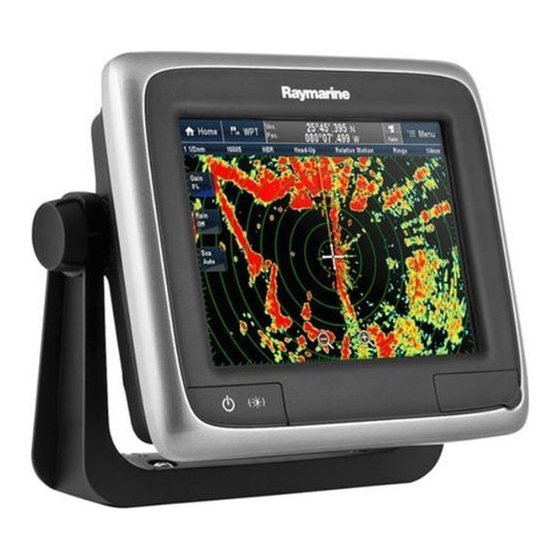
Important Information Intended Use The A65 is a GPS Chartplotter display unit that can be upgraded to include optional Fishfinder functionality. This handbook contains important information on the installation of your A65 display and RS12 GPS Antenna. To get the best results in operation and performance, please take the time to thoroughly read the accompanying Owner’s... -
Page 6: Emc Conformance
EMC Conformance All Raymarine equipment and accessories are designed to the best industry standards for use in the recreational marine environment. Their design and manufacture conforms to the appropriate Electromagnetic Compatibility (EMC) standards, but correct installation is required to ensure that performance is not compromised. -
Page 7: Suppression Ferrites
The following illustration shows typical cable suppression ferrites sometimes used with Raymarine equipment. To ensure EMC compliance, always use these ferrites, if supplied by Raymarine for use with this equipment. If not supplied by Raymarine, a ferrite is not required for use with this equipment. - Page 8 Protective covers have been attached at the factory on the SONAR, AUX and NMEA connectors on the rear of the A65. If you are not using one or more of these ports, please keep the cover attached to the connector to protect it from the elements.
-
Page 9: Chapter 1: Introduction
This manual provides information and instructions for installing your A65 display and RS12 GPS sensor. 1.1 Selecting the Display Unit Location Your A65 can be mounted using the mounting bracket supplied, or console mounted using the optional flush mount kit. Before you install the display, plan its installation, considering: •... -
Page 10: What Comes In The Box
A65 Installation Manual 1.2 What Comes in the Box Unpack the display carefully, to prevent damage. Save the carton and packing, in case the unit has to be returned for service. Power/Data Cable, 3 pin, 1.5m Frame Screws, part no. R08003... -
Page 11: Optional Equipment
The following optional items are also available to complete your system: Part No. Description E63070 DSM25, Digital Sounder Module, 200/50KHz, 500W E36017 Flush Mount Kit, A65 R69086 Network Cable, A65, 3.5m E36015 Network Cable, A65, 8.5m E36016 Network Cable, A65, 15m... -
Page 12: Unit Size
A65 Installation Manual 1.4 Unit Size The dimensions for your A65 display are as follows: 9.61in (244mm) ENTER 6.81in CANCEL (173mm) 7.83in PAGE ACTIVE (199mm) WPTS DATA MENU 9.88in (251mm) 11.02in (280mm) 2.56in 2.40in (61mm) (65mm) .866in (22mm) 3.43in 3.11in... -
Page 13: Chapter 2: Installing The Display Unit
Chapter 2: Installing the Display Unit The A65 display unit is waterproof to IPX-7 and can be installed either above or below deck using either the mounting bracket or by flush mounting into the console. 2.1 Mounting Note: The mounting bracket and the mount frame to which the bracket attaches must be removed prior to flush mounting. -
Page 14: Flush Mounting
A65 Installation Manual 5. Use the screws and nuts supplied to securely attach the bracket to the mount- ing surface. D7899-1 6. Attach the display unit to the bracket. 7. Adjust the unit angle for clear vision and tighten the knobs. -
Page 15: Cable Runs
Chapter 2: Installing the Display Unit CAUTION: Installation Make sure there are no hidden electrical wires or other items behind the selected location before proceeding. Make sure there is sufficient rear access for mounting AND CABLING. 1. Check the selected location for the unit. A clear, flat area with suitable clear- ance behind the panel, is required. -
Page 16: Making The Cable Connections
A65 Installation Manual 12V Power Supply RS12 A65 Display DSM25 Sounder Fluxgate Compass SONAR NMEA POWER Power Power Fishfinder NMEA Transducer Making the Cable Connections The cable connections are located on the back of the display unit as shown below:... -
Page 17: Power Supply
No insulation Power Supply The A65 is intended for use on boat’s DC power systems rated from 10.7 to 18 VDC. The power connection to the unit should be made at either the output of the battery isolator switch or at a DC power distribution panel. Power should be... -
Page 18: Nmea Cable (R08004)
A65 to reduce overall wire length. Only use enough wire to connect the unit to the power source, including a service loop. Note: When the A65 has been powered off using the PWR key but is still electrically con- nected to the power supply, the GPS continues to draw current. -
Page 19: Chapter 3: Installing The Gps Antenna
Chapter 3: Installing the GPS Antenna The RS 12 package contains the following items: 1. Low profile GPS Receiver, with 10 m (33 ft) cable 2. Flush mount gasket 3. Mounting studs (x2) and thumb nuts (x2) 4. Pole mount kit * Note: * If you intend to mount the receiver on a pole, you will need to obtain a suitable pole with 1 inch 14 TPI thread. -
Page 20: Cabling Route
A65 Installation Manual Cabling Route When planning the location for the unit, consider the best route for running the cable between the receiver and GPS display unit or to the rest of an integrated system. Ideally, you should try to route the cable so it is: •... -
Page 21: Surface Mounting
Chapter 3: Installing the GPS Antenna D8689-1 Surface Mounting 1. Use the template supplied in this handbook to mark the two 6 mm (0.25 in) mounting holes. 2. OPTION A: If the cable is going to pass through the mounting surface drill a 19 mm (0.75 in) center hole. -
Page 22: Making The Cable Connections
A65 Installation Manual Top view Underside view D8690-1 Making the Cable Connections Connect the cable to the connector Labeled GPS on the back of the display unit as shown below: RS12 A65 Display SONAR NMEA POWER www.Busse-Yachtshop.de email: info@busse-yachtshop.de... -
Page 23: Chapter 4: Maintenance
Chapter 4: Maintenance 4.1 Introduction This chapter provides information on maintaining and troubleshooting your A65 GPS Chartplotter and on how to get assistance from Raymarine. At regular intervals, carry out the following servicing procedures: • Routine checks. • Cleaning the Display. -
Page 24: Cleaning The Display
Settings Reset: using hardware keys or via the System Setup Menu. To carry out a Settings Reset using the hardware keys: 1. With the A65 powered OFF, press and hold the left hand soft key. 2. Press and release the POWER key to power ON the display, but continue to hold in the soft key. -
Page 25: Settings And Data Reset
4.3 Troubleshooting All Raymarine products are, prior to packing and shipping, subjected to comprehensive test and quality assurance programs. However, if your A65 should develop a fault, this section will help you to identify the most likely cause and show the corrective action required to restore normal operation. -
Page 26: Common Problems And How To Solve Them
A65 Installation Manual Common Problems and How to Solve Them Problem Solution Display is blank 1. Make sure that the power supply cable is sound and that all connections are tight and free from corrosion. 2. Check relevant fuses. 3. Make sure that Brightness level i s not set too low. -
Page 27: Upgrading The Display
1. Download the update file from the Raymarine website to your CompactFlash card, according to the instructions on the website. 2. With the A65 powered OFF, insert the CF card into the A65 chart card reader. 3. Power the A65 on. The following screen appears. - Page 28 6. Press Continue to confirm. When complete, the following message appears: “Upgrade Completed. Press ANY KEY to Continue”. 7. Press a key on the A65. The UPGRADE and REBOOT soft keys now replace the text. 8. Install any other upgrades as needed, using procedures listed above.
-
Page 29: Technical Support
If the answer you are seeking is not available, click the Ask Raymarine tab to submit your own question to our technical support staff, who will reply to you by e-mail. -
Page 30: Accessories And Parts
A65 Installation Manual Accessories and Parts You can obtain many Raymarine accessories and parts directly from your authorized Raymarine dealer. However, if your dealer does not have the item you want, contact Raymarine Technical Services at: 1-800-539-5539 extension 2333, or 1-603-881-5200 extension 2333. -
Page 31: Contacting Raymarine In Europe
Chapter 4: Maintenance Contacting Raymarine in Europe You can obtain Technical Support, service and accessories from your authorized Raymarine dealer, or by contacting: Raymarine plc Anchorage Park, Portsmouth PO3 5TD, England Tel +44 (0)23 9271 4713 Fax +44 (0)23 9269 4642 www.Busse-Yachtshop.de... - Page 32 A65 Installation Manual www.Busse-Yachtshop.de email: info@busse-yachtshop.de...
-
Page 33: Appendix: Specifications
Appendix: Specifications A65 LCD Color Display General Approvals CE - conforms to EN60945:2002 Mounting Bracket with dash (flush) mount option Size (H x W x D) 7.8 x 11.0 x 3.1 in (199 x 280x 79 mm), bracket mounted 6.8 x 9.6 x 2.4 in (173 x 244 x 61 mm), dash mounted Weight 3.09 lbs (1.40 kg), bracket mounted... -
Page 34: Chartplotter Features
A65 Installation Manual General Interfaces RS12 GPS Antenna DSM25 Sounder NMEA0183, receive and transmit CompactFlash card slot Waypoints 1000 waypoints entered via cursor, lat/long or at boat’s posi- tion. 16 character name can be assigned. 6 different waypoint symbols available... -
Page 35: Rs12 Gps Sensor
RS12 GPS Sensor Approvals CE - conforms to 1999/5/EC Dimensions: diameter: 3.7 in (95 mm) height: 1.2 in (30 mm); 2.4 in (62 mm) with pole mount Weight: 15.3 oz (0.435 kg) Cable length: 33 ft (10 m) Receiver type: SD-GPS, WAAS/EGNOS/MSAS ready, 12 parallel chan- nels Operating conditions:... - Page 36 A65 Installation Manual www.Busse-Yachtshop.de email: info@busse-yachtshop.de...
-
Page 37: Index
Flush mounting 14 Connections, A65 16 Fuse 17 Supply, A65 17 Installation 13 Problem solving 26 Specifications 33 Reset 24 Bracket mounting, A65 13 RS12 Cable connections 22 Cable Pole mounting 20 Connections, A65 16 Specifications 35 Connections, RS12 22... - Page 38 A65 Installation Manual www.Busse-Yachtshop.de email: info@busse-yachtshop.de...