Yamaha QY100 Service Manual
Music sequencer
Hide thumbs
Also See for QY100:
- Owner's manual (292 pages) ,
- Bedienungsanleitung (292 pages) ,
- Data list (72 pages)
Table of Contents
Advertisement
Quick Links
This document is printed on chlorine free (ECF) paper with soy ink.
SY
011558
20001220-59000
SERVICE MANUAL
CONTENTS
Midi Data Format ............................................................ 45
Midi Implementation Chart ......................................... 70
OVERALL CIRCUIT DIAGRAM
................................................ 3/5
.................................... 7
............................ 9
............... 10
............................ 11
.............................. 13
................................. 15
........................................ 18
............................ 21/30
....................... 39/42
HAMAMATSU, JAPAN
1.494K-408 K
Printed in Japan 2000.12
QY100
1
Advertisement
Table of Contents

Related Manuals for Yamaha QY100


Summary of Contents for Yamaha QY100
- Page 1 QY100 SERVICE MANUAL CONTENTS SPECIFICATIONS ..........3/5 PANEL LAYOUT ........7 BLOCK DIAGRAM ......9 CIRCUIT BOARD LAYOUT ....10 DISASSEMBLY PROCEDURE ......11 LSI PIN DESCRIPTION ......13 IC BLOCK DIAGRAM ......... 15 CIRCUIT BOARDS ........18 TEST PROGRAM ......
- Page 2 IMPOR TANT NOTICE This manual has been provided for the use of authorized Yamaha Retailers and their service personnel. It has been assumed that basic service procedures inherent to the industry, and more specifically Yamaha Products, are already known and under- stood by the users, and have therefore not been restated.
-
Page 3: Specifications
QY100 SPECIFICATIONS Sequencer block Data capacity approximately 32,000 notes Note resolution 480 clocks per quarter note Polyphony 64 notes Tempo 25-300 Modes SONG mode (SONG, SONG VOICE, SONG EFFECT) PATTERN mode (PATTERN, PATTERN VOICE, PATTERN EFFECT) Record modes Realtime replace, Realtime overdub, Step, Multi... -
Page 4: Power Supply
* Specifications and descriptions in this owner’s manual are for information purposes only. Yamaha Corp. reserves the right to change or modify products or specifications at any time without prior notice. Since specifications, equipment or options may not be the same in... - Page 5 QY100...
- Page 6 QY100...
-
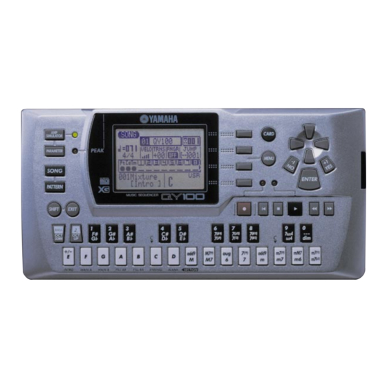
Page 7: Panel Layout
QY100 PANEL LAYOUT Front Panel Left Side Panel Rear Panel POWER Switch LCD Display & CONTRAST Control [SONG] Button [PATTERN] Button [SHIFT] Button [EXIT] Button Cursor Buttons [-1/NO] and [+1/YES] Buttons [MENU] and Function Buttons [ENTER] Button Sequencer Buttons Micro Keyboard... - Page 8 QY100 Rear Panel Right Side Panel DC IN Jack MIDI IN & OUT Connectors LINE OUT/PHONES Jack TO HOST Connector & HOST SELECT Switch FOOT SW Jack GUITAR/MIC INPUT Jack CARD Slot...
- Page 9 (CN2-5~11, 12~19) Port x7(SW7x8) (CN2-4~10,11~19) Host-sel monitor Battery monitor CARD LCD UNIT 1MHz clock out HOST SELECT 128 X 64dots P.bat monitor 8.4672MHz (CN1-7,8) PEAK SMART CONTRAST IC22 TO HOST TxD0, RxD0 MEDIA Battery backup transceiver (CN1-2) (CN1-4~19) IC23 Port x3 (CN1-1~5) RxD1 main CPU...
-
Page 10: Circuit Board Layout
QY100 CIRCUIT BOARD LAYOUT LCD Ass'y WIRING LCD unit to Battery DC IN 28CA2-8817683... -
Page 11: Disassembly Procedure
QY100 DISASSEMBLY PROCEDURE Bottom Cover 1-1. Remove the four (4) screws marked [80] and one (1) screw marked [70]. The Bottom cover can then be removed. (Fig. 1) [80] [70] [80] [80] [80] [70]: Bind Head Screw 2.6 X 8 MFZN2Y (EG320030) [80]: Bind Head Tapping Screw-P 2.6 X 8 MFZN2BL (EP620120) - Page 12 QY100 PN Circuit Board 3-1. Remove the bottom cover. (See Procedure1.) 2-2. Remove the DM circuit board. (See Procedure2.) 3-3. Remove the nine (9) screws marked [T80] and then remove the shield bracket. (Fig. 3) 3-4. Remove the six (6) screws marked [T60]. The PN circuit board can then be removed.
-
Page 13: Lsi Pin Description
QY100 LSI PIN DESCRIPTION HG73C205AFD (XU947C00) SWX00B TONE GENERATOR DM: IC1, IC2 NAME FUNCTION NAME FUNCTION Initial clear CMA3 Program address bus RFCLKI PLL Clock CMA8 Program address bus PLL Control CMA2 Program address bus AVDD_PLL Power supply read signal... - Page 14 QY100 T6963C (XL166A00) CPU (LCD Controller) DM: IC8 NAME FUNCTION NAME FUNCTION /HALT "H" : Normal "L" : Clock oscillation stopped (Home address and data of area digit number are Read/write signal output terminal to display preserved.) memory ("H" -> Read, "L" -> Write) /RESET "H"...
- Page 15 QY100 µ PD63200GS-E1 (XP867A00) DAC (Digital to Analog Converter) NAME FUNCTION NAME FUNCTION 4/8F 4/8 Fs selection R. REF Channel R voltage reference D. GND Digital ground L. REF Channel L voltage reference 16 BIT L. OUT 16 bit/18 bit selection Channel L output D.
-
Page 16: Ic Block Diagram
QY100 IC BLOCK DIAGRAM HD29051FP(XV708A00) TC74HC374FPEL(XL342A00) TC74LV164AFPEL(IS016400) DM: IC22 DM: IC10 DM: IC44 Line Transceiver Octal 3-Stage D-FF Shift Resister OUTPUT SIRIAL CONTROL INPUT D CK OUTPUTS D CK OUTPUTS CLEAR CLEAR D CK CLOCK D CK CLOCK SC7SU04FEL(XI348A00) M5291FP-600C(XR858A00) - Page 17 QY100 TC74VHC273F(EL)(XY254A00) TC74VHC244F(XT800A00) TC7W74FU(XN243A00) TC74VHCT244AF-EL(XU230A00) DM: IC13, 19 DM: IC39 Octal D-FF D-FF DM: IC12, 41 Buffer CLEAR VD(Vcc) CLOCK (GND)Vss M5216FP-600C(XP263A00) TC7WH32FU(XY36A00) TC74VHC32F(EL)(XY537A00) TC74VHCT32AFT-EL(XZ372A00) DM: IC30 DM: IC14, 15, 36, 40, 45 Operating Amplifier DM: IC14, 15, 36, 40, 45...
-
Page 18: Circuit Boards
QY100 CIRCUIT BOARDS DM Circuit Board VOLUME ON STANDBY to Battery LINE OUT/ PHONES DC IN GAIN GUITAR/ INPUT CONTRAST FOOT SW MIDI CN1: to LCD unit CN2: to PN-CN1 TO HOST HOST SELECT PC-2 PC-1 MIDI 3.3V CARD Component side... - Page 19 QY100 Pattern side...
- Page 20 QY100 PN Circuit Board CARD SIMULATOR PARAMETER MENU SONG ENTER PATTERN SHIFT EXIT BASS 7(#9) 7( 13) 7(#11) 7SUS4 7( 9) 7(13) 7(#5) SUS4 DOWN add9 M7(9) 7(9) add9 m7(9) m7(11) m7( 5) INTRO MAIN MAIN FILL FILL ENDING BLANK SECTION...
-
Page 21: Test Program
QY100 TEST PROGRAM Item Judgment conditions, etc. Starting test program Normal testing procedure & testing procedure in case of NG Testing procedure when judged as NG System RAM test OK/NG RAM battery check OK/NG Power battery check OK/NG LCD test... - Page 22 When testing in the MANUAL mode is initiated, the screen [SONG] keys simultaneously, turn on the power to the main of the display unit appears as shown below. unit. Then the screen of the display unit appears as shown QY100 TEST MANUAL below. MAIN ROM Ver #.## SUB CPU Ver #.##...
- Page 23 QY100 3. POWER BATTERY TEST Display of Test Results Initial Display 01: RAM R/W QY100 TEST MANUAL MAIN ROM Ver=#.## SUB CPU Ver=#.## 01: RAM R/W 03:Power Battery [ENTER]:Test Start [-1,+1]:INC,DEC Test End [F4]:Exit Testing ends after the test result is displayed. Press the...
- Page 24 6. PANEL SWITCH TEST Vertical stripes at every other dot are displayed followed by Initial Display black/white inverted blinking of the dot display at about 1 QY100 TEST MANUAL second intervals. Check LCD dots for this operation visually. MAIN ROM Ver=#.## Check that the contrast can be varied for the easy-to-see SUB CPU Ver=#.##...
- Page 25 For what to be done HOST SELECT TEST when an NG judgment is made during testing, refer to B. Initial Display HOW TO PROCEED TESTING. QY100 TEST MANUAL 7. MIDI IN/OUT TEST MAIN ROM Ver=#.## Initial Display SUB CPU Ver=#.##...
- Page 26 Distortion of 1.0% or less (Load 33 ohm JIS C filter) Initial Display When the volume is at the minimum: LCD Display -70dBm or less (Load 33 ohm JIS C filter) QY100 TEST MANUAL Test end MAIN ROM Ver=#.## AUO mode: Pressing the [+1] key will end the sound output SUB CPU Ver=#.##...
- Page 27 14. STYLE ROM TEST AUO mode: Pressing the [+1] key will end the sound output Initial Display and “13. SMART MEDIA” test will be executed. QY100 TEST MANUAL MANUAL mode: Pressing the [F4] key will end the sound MAIN ROM Ver=#.## output and the program will be in the test number input SUB CPU Ver=#.##...
- Page 28 OUTPUT R: -50dBm or less (Load 33ohm JIS C filter) 17. FOOT SW TEST Initial Display Test End QY100 TEST MANUAL AUTO mode: Pressing the [+1] key will end testing and “16. MAIN ROM Ver=#.## EFFECT RAM R” test will be executed.
- Page 29 QY100 Factory setting of the following data will be executed when 19. EXIT the [YES] key is pressed. Initial Display • System data QY100 TEST MANUAL • Song data MAIN ROM Ver=#.## • Sequence data SUB CPU Ver=#.## No factory setting will be executed when the [NO] key is pressed.
- Page 30 QY100...
- Page 31 QY100...
- Page 32 QY100...
- Page 33 QY100...
- Page 34 QY100...
- Page 35 QY100...
- Page 36 QY100...
- Page 37 QY100...
- Page 38 QY100...
-
Page 39: Error Messages
When a song or style file is loaded and previous data in the destination song or style file will be erased. NotEnough Memory A song file or style file could not be loaded because the QY100's inter- nal memory is not enough. -
Page 40: Memory Card
No Card This message will appear if you press the [CARD] button when no memory card is in the QY100 CARD slot (or a card has not been prop- erly inserted). Make sure a memory card is properly inserted in the CARD slot before pressing the [CARD] button. - Page 41 Cannot Open The specified file cannot be loaded. Wrong ID You have attempted to load a file that was not saved using the QY100 format. SMF Error[00] You have attempted to load an SMF file but the file to be loaded does not have the proper SMF format.
- Page 42 QY100...
- Page 43 QY100...
- Page 44 QY100...
-
Page 45: Midi Data Format
QY100 MIDI DATA FORMAT Tone generator part (1) TRANSMIT FLOW MIDI < NOTE ON/OFF PITCH BEND EnH, MODURATION WHEEL BnH,01H SYSTEM EXCLUSIVE MESSAGE <BULK DUMP> XG SYSTEM F0H 43H 0nH 4CH bbH bbH aaH aaH aaH ddH..ddH ccH F7H MULTI EFFECT F0H 43H 0nH 4CH bbH bbH aaH aaH aaH ddH..ddH ccH F7H... - Page 46 QY100 DATA ENTRY DEC BnH,61H NRPN VIBRATO RATE BnH,63H,01H,62H,08H,06H,mmH VIBRATO DEPTH BnH,63H,01H,62H,09H,06H,mmH VIBRATO DELAY BnH,63H,01H,62H,0AH,06H,mmH FILTER CUTOFF FREQ. BnH,63H,01H,62H,20H,06H,mmH FILTER RESONANCE BnH,63H,01H,62H,21H,06H,mmH AEG ATTACK TIME BnH,63H,01H,62H,63H,06H,mmH AEG DECAY TIME BnH,63H,01H,62H,64H,06H,mmH AEG RELEASE TIME BnH,63H,01H,62H,66H,06H,mmH DRUM INST CUTOFF FREQ. BnH,63H,14H,62H,rrH,06H,mmH FILTER RESONANCE BnH,63H,15H,62H,rrH,06H,mmH...
- Page 47 QY100 (3) TRANSMIT/RECEIVE DATA (3-1) CHANNEL VOICE MESSAGES (3-1-1) NOTE OFF STATUS 1000nnnn (8nH) n = 0 ~ 15 VOICE CHANNEL NUMBER NOTE NUMBER 0kkkkkkk k = 0 (C-2) ~ 127 (G8) VELOCITY 0vvvvvvv v is ignored Received only. (3-1-2) NOTE ON/OFF...
- Page 48 QY100 (3-1-6) CONTROL CHANGE STATUS 1011nnnn (BnH) n = 0 ~ 15 VOICE CHANNEL NUMBER CONTROL NUMBER 0ccccccc CONTROL VALUE 0vvvvvvv * The CONTROL NUMBER to be transmitted. c = 0 BANK SEL MSB ; v = 0 :XG NORMAL,...
- Page 49 The following Bank Select related operations will all occur when a Program Change is received. Bank Select MSB:60h-6Fh are not sounded on models which do not support GMx, but since on the QY100 these are for future expansion of melodic voices, they will be sounded for the present by MSB00h.
- Page 50 QY100 (3-2-4) OMNI MODE OFF (CONTROL NUMBER = 7CH , DATA VALUE = 0) Performs the same processing as when ALL NOTE OFF is received. Sets the VOICE RECEIVE CHANNEL to OMNI OFF and CHANNEL = 1. (3-2-5) OMNI MODE ON (CONTROL NUMBER = 7DH , DATA VALUE = 0) Performs the same processing as when ALL NOTE OFF is received.
- Page 51 QY100 01H 20H mmH — FILTER CUTOFF FREQUENCY 00H - 40H - 7FH (-64 - 0 - +63) 01H 21H mmH — FILTER RESONANCE 00H - 40H - 7FH (-64 - 0 - +63) 01H 63H mmH — EG ATTACK TIME...
- Page 52 QY100 (3-6-3) PARAMETER CHANGE (3-6-3-1) MIDI MASTER TUNING F0H 43H 1nH 27H 30H 00H 00H mmH llH ccH F7H Modifies the MASTER TUNE value. The values of mm and ll are used as the MIDI Master Tuning. (n and cc values are ignored.)
- Page 53 QY100 00000000 Data 0ccccccc ccccccc Check-sum 11110111 End of Exclusive For Addresses and Byte Counts, refer to the attached tables. Check sum is the value which produces a lower 7 bits of zero when the Byte Count, Start Address, Data, and the Check-sum itself are added.
- Page 54 QY100 (4) Diagram of connections between the Keyboard/ Switch block, Sequencer block, and Tone Generator block MIDI IN KEYBOARD (TO HOST) Selected Track Filter REC SEQUENCER PLAY SEQUENCER MIDI OUT TONE GENERATOR (TO HOST) When PC1, PC2 or, Mac is selected with the HOST SELECT switch, data will be transmitted and received via the TO HOST connector.
- Page 55 QY100 Sequencer part (1) TRANSMIT FLOW MIDI < CHANNEL VOICE MESSAGE NOTE ON/OFF KEY’S AFTER TOUCH CONTROL CHANGE PROGRAM CHANGE CHANNEL AFTER TOUCH PITCH BEND CHANGE CHANNEL MODE MESSAGE ALL SOUND OFF BnH 78H RESET ALL CONTROLLERS BnH 79H LOCAL CONTROL...
- Page 56 MONO MODE ON BnH 7EH POLY MODE ON BnH 7FH (3-3) SYSTEM COMMON MESSAGE These are transmitted and received as Control Messages for QY100 functions. They are not recorded as SEQUENCE DATA. (3-3-1) SONG POSITION POINTER STATUS 11110010 (F2H) 0vvvvvvv...
- Page 57 QY100 (2) RECEIVE FLOW MIDI > <CHANNEL VOICE MESSAGE> NOTE OFF NOTE ON/OFF KEY’S AFTER TOUCH CONTROL CHANGE PROGRAM CHANGE CHANNEL AFTER TOUCH PITCH BEND CHANGE CHANNEL MODE MESSAGE ALL SOUND OFF BnH 78H RESET ALL CONTROLLERS BnH 79H LOCAL CONTROL...
- Page 58 MONO MODE ON BnH 7EH POLY MODE ON BnH 7FH (3-3) SYSTEM COMMON MESSAGE These are transmitted and received as Control Messages for QY100 functions. They are not recorded as SEQUENCE DATA. (3-3-1) SONG POSITION POINTER STATUS 11110010 (F2H) 0vvvvvvv...
- Page 59 (3-6-1) UNIVERSAL NON REALTIME MESSAGE (3-6-1-1) IDENTITY REQUEST (Received only) F0H 7EH 0nH 06H 01H F7H (n is device number however, the QY100 receives when in OMNI.) (3-6-1-2) IDENTITY REPLY (Transmitted only) F0H 7EH 7FH 06H 02H 43H 00H 41H ddH ddH 00H 00H 00H 01H F7H dd;Device Number Code...
- Page 60 QY100 (3-6-3-2) Bulk Dump DATA The format for transmission and reception of SETUP DATA, SONG INFORMATION and PATTERN INFORMATION. Refer to <Table 1-9> for Address and Data size. 11110000 Exclusive status 01000011 YAMAHA ID 00000000 substatus 01011111 model ID 0bbbbbbb...
- Page 61 QY100 <Table 1-1> Parameter Base Address Parameter Change Address (H) (M) (L) Description SYSTEM System Drum Setup Reset XG System On All Parameter Reset INFORMATION System Information EFFECT 1 Effect1 (Reverb,Chorus,Variation ) Reserved MULTI PART Multi Part 1 Multi Part 32 Reserved →...
- Page 62 QY100 < Table 1-4 > MIDI Parameter Change table ( EFFECT 1) Address Size Data Parameter Name Description Default value 02 01 00 00..7F Reverb Type MSB Refer to Effect Type List 01 (=HALL1) 00..7F Reverb Type LSB 00 : basic type 00..7F...
- Page 63 QY100 Address Size Data Parameter Name Description Default value 00..7F Variation Param 7 MSB Refer to Ef. Parameter List depends on vari. type 00..7F Variation Param 7 LSB Refer to Ef. Parameter List depends on vari. type 00..7F Variation Param 8 MSB Refer to Ef.
- Page 64 QY100 In the Bit Map Data, only the specified elements can also be received. At this time, other elements are displayed in their previous condition. Parameter changes for DISPLAY DATA can be constantly transmitted from the specified region. < Table 1-6 >...
- Page 65 QY100 Address Size Data Parameter Name Description Default value nn 35 00..01 Not Used nn 36 00..01 Not Used nn 37 00..01 Not Used nn 38 00..01 Not Used nn 39 00..01 Not Used nn 3A 00..01 Not Used nn 3B 00..01...
- Page 66 QY100 nn = PartNumber For the Drum Part, the following parameters have no effect. • Bank Select LSB • Portamento • Soft Pedal • Mono/Poly • Scale Tuning • Pitch EG < Table 1-7 > MIDI Parameter Change table ( DRUM SETUP )
- Page 67 QY100 CHORUS TYPE TYPE MSB TYPE LSB [00]No Effect No Effect No Effect [01]Chorus 1 [02]Chorus 2 [03]Chorus 3 [04]Chorus 4 [05]Celeste 1 [06]Celeste 2 [07]Celeste 3 [08]Celeste 4 [09]Flanger 1 [10]Flanger 2 [11]Flanger 3 No Effect No Effect No Effect...
- Page 68 QY100 < Table 1-9 > SEQUENCER PARAMETER ADDRESS Address Size Description QY100 (P=1) QY70(P=0) Recv Trans Recv SYSTEM bulk mode on/off BULK DUMP SONG song 1 song 2 song (nn+1) song 20 song all BULK DUMP PATTERN user pattern 1...
- Page 69 QY100 Decimal↔Hexadecimal↔Binary Correspondence List Many MIDI messages listed in the MIDI Data Format section are expressed in hexadecimal or binary numbers. Hexadecimal numbers may include the letter “H” as a suffix. The letter “n” indicates a certain whole number. The chart below lists the corresponding decimal number for each hexadecimal/binary number.
-
Page 70: Midi Implementation Chart
QY100 YAMAHA [ Music Sequencer --- voice part Date:06-OCT-2000 Model QY100 MIDI Implementation Chart Version : 1.0 +----------------------------------------------------------------------+ Transmitted Recognized Remarks Function ... | |-------------------+----------------+----------------+----------------| |Basic Default | 1 - 16 | 1 - 16 | Memorized |Channel Changed | 1 - 16... - Page 71 QY100 YAMAHA [ Music Sequencer --- sequencer part Date:06-OCT-2000 Model QY100 MIDI Implementation Chart Version : 1.0 +----------------------------------------------------------------------+ Transmitted Recognized Remarks Function ... | |-------------------+----------------+----------------+----------------| |Basic Default | 1 - 16 | 1 - 16 | Memorized |Channel Changed |-------------------+----------------+----------------+----------------|...
-
Page 72: Parts List
PARTS LIST CONTENTS OVERALL ASSEMBLY ..........2 ELECTRICAL PARTS ..........4 Notes : DESTINATION ABBREVIATIONS A : Australian model M : South African model B : British model O : Chinese model C : Canadian model Q : South-east Asia model D : German model T : Taiwan model E : European model... - Page 73 QY100 OVERALL ASSEMBLY T20b T20d T20c T20d T100 T20a...
- Page 74 QY100 PART NO. DESCRIPTION REMARKS REF NO. RANK QY100 Overall Assembly (V674560) Overall Assembly (V675130) Top Assembly (V671080) V 6 5 5 6 5 0 0 Bottom Cover V 6 5 6 1 8 0 0 Spring C V 6 5 6 1 9 0 0...
- Page 75 QY100 ELECTRICAL PARTS PART NO. DESCRIPTION REMARKS REF NO. RANK ELECTRICAL PARTS V 6 5 9 6 2 0 0 Circuit Board (XZ117D0) V 6 5 9 6 3 0 0 Cirucit Board (XZ241D0) V 6 5 9 6 2 0 0...
- Page 76 QY100 PART NO. DESCRIPTION REMARKS REF NO. RANK US064100 Ceramic Cap.-B (chip) 0.0100 50V K US062680 Ceramic Cap.-SL (chip) 680P 50V J UF037100 Electrolytic Cap. (chip) 10 16V UF037470 Electrolytic Cap. (chip) 47 16V US063220 Ceramic Cap.-B (chip) 2200P 50V K US064100 Ceramic Cap.-B (chip)
- Page 77 QY100 PART NO. DESCRIPTION REMARKS REF NO. RANK IC33 XS346A00 SI-8501L +5V 1.0A REGULATOR +5V IC34 XN883A00 TC7W14FU INVERTER IC35 X I 3 4 8 A 0 0 SC7SU04FEL INVERTER IC36 XZ372A00 TC74VHCT32AFT-EL OR-GATE IC37 XS775A00 TC7SH04FU INVERTER IC39 XN243A00...
- Page 78 QY100 PART NO. DESCRIPTION REMARKS REF NO. RANK RD357470 Carbon Resistor (chip) 47K 63M J RD156180 Carbon Resistor (chip) 1.8K 1/4 J RD156180 Carbon Resistor (chip) 1.8K 1/4 J RD355150 Carbon Resistor (chip) 150 63M J RD357100 Carbon Resistor (chip)
- Page 79 QY100 PART NO. DESCRIPTION REMARKS REF NO. RANK R168 RD356470 Carbon Resistor (chip) 4.7K 63M J R169 RD356470 Carbon Resistor (chip) 4.7K 63M J R170 RD355220 Carbon Resistor (chip) 220 63M J R171 RD355220 Carbon Resistor (chip) 220 63M J...
- Page 80 QY100 OVERALL CIRCUIT DIAGRAM ( DM , PN ) QY100 INVERTER INVERTER (from G5) INVERTER (to N3) INVERTER INVERTER (to H9) INVERTER SYSTEM RESET (from I4) ROM 16M BUFFER (from G2) INVERTER BUFFER (from K2) LINE TRANSCEIVER INVERTER (from E2)