Jenn-Air PRG3010 series Service
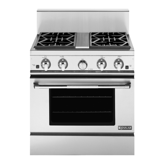
Gas range
Hide thumbs
Also See for Jenn-air PRG3010 series:
- User manual (48 pages) ,
- Installation manual (18 pages) ,
- Installation manual (56 pages)
Table of Contents
Advertisement
Quick Links
Service
This manual is to be used by qualified appliance
technicians only. Maytag does not assume any
responsibility for property damage or personal
injury for improper service procedures done by
an unqualified person.
Gas
Range
This Base Manual covers general information
Refer to individual Technical Sheet
for information on specific models
This manual includes, but is
not limited to the following:
PRG3010*
PRG3610*
PRG4810*
16022882
December 2004
Advertisement
Chapters
Table of Contents
Troubleshooting

Related Manuals for Jenn-Air Jenn-air PRG3010 series


Summary of Contents for Jenn-Air Jenn-air PRG3010 series
- Page 1 Service This manual is to be used by qualified appliance technicians only. Maytag does not assume any responsibility for property damage or personal injury for improper service procedures done by an unqualified person. This Base Manual covers general information Refer to individual Technical Sheet...
-
Page 2: Important Information
Important Notices for Servicers and Consumers Maytag will not be responsible for personal injury or property damage from improper service procedures. Pride and workmanship go into every product to provide our customers with quality products. It is possible, however, that during its lifetime a product may require service. -
Page 3: Table Of Contents
Testing Procedures ..........16 - 17 Griddle Ignitor ............22 Griddle Thermal Valve .......... 22 Griddle Thermostat ..........22 Dual Valve ............23 Single Thermal Valve ..........23 Appendix A Installation Instructions ........A-2 16022882 Rev. 0 ©2004 Maytag Services... -
Page 4: Safety Information
14 inches W.C.P. WARNING To avoid risk of electrical shock, property damage, personal injury or death; verify wiring is correct, if components were replaced. Verify proper and complete operation of unit after servicing. 16022882 Rev. 0 ©2004 Maytag Services... -
Page 5: Safety Practices For Servicer
Electrical Code. Do not use an extension cord with this appliance. • Insure all packing materials are removed from the range before operating it, to prevent fire or smoke damage should the packing material ignite. 16022882 Rev. 0 ©2004 Maytag Services... -
Page 6: Oven
Do not let a potholder touch the flame. Do not use a towel or a bulky cloth as a potholder. • Never leave range unattended while cooking. Boilovers can cause smoking and may ignite. 16022882 Rev. 0 ©2004 Maytag Services... -
Page 7: Baking, Broiling, And Roasting
These items may ignite causing a fire. CAUTION Do not store items of interest to children in cabinets above range. Children may climb on oven to reach these items and become seriously injured. 16022882 Rev. 0 ©2004 Maytag Services... -
Page 8: Electrical Requirements
Larger slot on adapter must be aligned with larger slot in the wall receptacle to provide proper polarity. 16022882 Rev. 0 ©2004 Maytag Services... -
Page 9: Product Safety Devices
If any ground wire, screw, strap, nut, etc. is removed for service, or any reason, it must be reconnected to its original position with original fastener before the appliance is put into operation again. Failure to do so can create a possible shock hazard. 16022882 Rev. 0 ©2004 Maytag Services... -
Page 10: General Information
Cooking Nomenclature Style ® PRO-STYLE Brand Jenn-Air Fuel Type Liquid Propane Natural Gas Product Type Range Features Feature Level Feature Level Unit Fuel Dual Fuel Unit Size Range (30") Range (36") Range (48") 16022882 Rev. 0 ©2004 Maytag Services... -
Page 11: Rating Label
Therefore, 120 VAC should never be applied directly to heat generated by the heater, which causes the bi-metal the oven valve terminals. The glow bar is the power to bend. source for the oven valve. 16022882 Rev. 0 ©2004 Maytag Services... -
Page 12: Specifications
• For product in Canada call 1-866-587-2002 or visit the Web Sites at www.jennair.com Warranty service must be performed by an authorized servicer. We also recommend contacting an authorized servicer, if service is required after warranty expires. 16022882 Rev. 0 ©2004 Maytag Services... -
Page 13: Troubleshooting Procedures
• Check 120 VAC to ignitor, if no No voltage from control ....... No oven operation in bake or broil. voltage, replace control. • Verify all connections are clean Loose wire connection or broken wire..and tight, replace broken wire. 16022882 Rev. 0 ©2004 Maytag Services... - Page 14 Fan motor does not operate. next step. Failed fan motor or winding or frozen shaft. • Check motor winding for continuity. Check for a frozen motor shaft. Check for broken wiring between motor and neutral terminal block. 16022882 Rev. 0 ©2004 Maytag Services...
-
Page 15: Troubleshooting Procedures
Oven smokes/odor first few usage. times of usage • Ventilate area well and perform self-clean cycle. • See Testing Procedures for Electronically Controlled......Failure Codes diagnostic checks. 16022882 Rev. 0 ©2004 Maytag Services... -
Page 16: Testing Procedures
Approximately 1100 Ω at room Temperature sensor Measure resistance. temperature 80 º Convection motor fan Verify supply voltage ......120 VAC Measure continuity at the following points: Terminal to terminal......Continuity Terminal to ground ......Infinite 16022882 Rev. 0 ©2004 Maytag Services... - Page 17 Unplug switch harness. Test for 120 VAC continuity at wire terminals. Switch in any position......Continuity Top surface burner Verify gas is supplied ......Check for obstructions in burner ports. Verify burner cap is positioned correctly. 16022882 Rev. 0 ©2004 Maytag Services...
-
Page 18: Disassembly Procedures
9. Remove screws securing side panels to chassis. NOTE: All screws on the rear on each side, all screws on front, and one screw located on each front inside corner of the maintop facing the sides (if equipped). 16022882 Rev. 0 ©2004 Maytag Services... -
Page 19: Burner Switch
6. Remove valve clamp. NOTE: Check for leaks before installing control panel. 7. Reverse procedure to reassemble. NOTE: When reinstalling, ensure valve and gasket is seated on manifold and tighten down valve clamp evenly. 16022882 Rev. 0 ©2004 Maytag Services... -
Page 20: Dual Feed Burner Base
6. Gently lower fan and place on the oven bottom. 7. Disconnect and label wire terminals on fan. NOTE: When reinstalling, install screws into center holes on convection fan to assist in aligning corner holes. 16022882 Rev. 0 ©2004 Maytag Services... -
Page 21: Selector Switch
NOTE: In the event that the oven door is off of the oven compressed together again for proper door and hinges are not closed together, the hinges installation. will need to be compressed and copper clip needs to be closed. 16022882 Rev. 0 ©2004 Maytag Services... -
Page 22: Oven Ignitor
5. Lift griddle assembly straight upward to gain access to thermostat capillary tube. 6. Slide the thermostat capillary tube out of the griddle plate channel and place to the side. 7. Remove griddle assembly from the unit. 8. Reverse procedure to reassemble. 16022882 Rev. 0 ©2004 Maytag Services... -
Page 23: Dual Valve
6. Remove screw securing burner, located at the rear of the burner. 7. Disconnect gas line from the single valve. 8. Remove nuts securing single valve to mounting bracket. 9. Reverse procedure to reassemble. 16022882 Rev. 0 ©2004 Maytag Services... - Page 24 Disassembly Procedures To avoid risk of electrical shock, personal injury or death; WARNING disconnect power to unit before servicing. This page intentionally left blank. 16022882 Rev. 0 ©2004 Maytag Services...
- Page 25 Appendix A 16022882 Rev. 0 A–1 ©2004 Maytag Services...
- Page 26 Professional 48², 36², 30² Gas Range Models 403 WEST FOURTH STREET, NORTH · NEWTON, IA 50208 Retain this manual for future reference. (17663 Rev. B) 8101P601-60 (05-04-03) A–2 16022882 Rev. 0 ©2004 Maytag Services...
- Page 27 30² GAS RANGE MODEL 36² GAS RANGE MODEL MODEL PRG3010 MODEL PRG3610 48² GAS RANGE MODEL MODEL PRG4810 16022882 Rev. 0 A–3 ©2004 Maytag Services...
- Page 28 Follow the gas supplier’s instruction. If you cannot reach your gas supplier, call the fire department. Installation and service must be performed by a qualified installer, service agency, or the gas FIGURE 1 supplier. A–4 16022882 Rev. 0 ©2004 Maytag Services...
-
Page 29: Step 1: Ventilation Requirements
(24² Deep x Unit Width) (30² Deep x 36² At Bottom) BLOWER 48² RANGE - 800-1000 CFM 800-1000 CFM 600-800 CFM 36² RANGE - 600-800 CFM 30² RANGE - 500 CFM 500 CFM 16022882 Rev. 0 A–5 ©2004 Maytag Services... -
Page 30: Step 2: Cabinet Preparation
13². projecting, depending on the countertop depth. See (PRG3610) (PRG3010) FIGURE 2A FIGURE 2B (PRG4810) FIGURE 2C A–6 16022882 Rev. 0 ©2004 Maytag Services... - Page 31 FIGURE 3A FIGURE 3B TABLE 2 DIMENSIONS PRG4810 27-7/16² 44-11/16² 12² 21-1/4² 29-15/16² 28-3/16² 10² 2-1/2² PRG3610 27-7/16² 44-11/16² 12² 21-1/4² 29-15/16² 28-3/16² 10² 2-1/2² PRG3010 26-3/4² 44-1/4² 9² 21-1/4² 29-15/16² 28-3/16² 9-3/8² 1-3/4² 16022882 Rev. 0 A–7 ©2004 Maytag Services...
-
Page 32: Step 3: Unpacking, Moving And Placing The Range
Figure 6). Flex Line to Range Manual Shut-Off Valve must be Easily Accessible Range Must be Uniformly Supported on Braces 2² Maximum Protrusion from Wall for Gas Supply FIGURE 4 Leveling Legs FIGURE 6 A–8 16022882 Rev. 0 ©2004 Maytag Services... -
Page 33: Griddle Adjustments
Replace the kick panel and oven doors by desired slope. The center screw is for shipping and reversing the procedure described previously. should be removed. 16022882 Rev. 0 A–9 ©2004 Maytag Services... -
Page 34: Anti-Tip Installation Instructions
(2) screws used to secure the · FOLLOW ALL INSTALLATION kick plate (Figure 5). INSTRUCTIONS. NOTE: Ensure that power is disconnected from the range before the kick plate is removed. A–10 16022882 Rev. 0 ©2004 Maytag Services... -
Page 35: Step 4: Electrical Connections
(AGA, CGA, or U.L.). Never use a hose made of rubber or other synthetic material, as the heat may cause the hose to melt and develop leaks. 16022882 Rev. 0 A–11 ©2004 Maytag Services... -
Page 36: Step 6: Backguard Installation
* Improper or lack of adjustments will void your warranty. This must be done before using the range for the first time and with proper ventilation. A–12 16022882 Rev. 0 ©2004 Maytag Services... -
Page 37: Installer Final Check List
Griddle is level. Drip trays are properly in place and pull out freely. Oven door hinges seated and door opens and closes properly. Burner grates correctly positioned, level, and do not rock. 16022882 Rev. 0 A–13 ©2004 Maytag Services...