Xerox Phaser 8860 Service Manual
Hide thumbs
Also See for Phaser 8860:
- System administrator manual (133 pages) ,
- Service documentation (15 pages) ,
- Voluntary product accessibility template (11 pages)
Table of Contents
Advertisement
Quick Links
Advertisement
Chapters
Table of Contents
Troubleshooting

Related Manuals for Xerox Phaser 8860

Summary of Contents for Xerox Phaser 8860
- Page 1 Phaser 8860/8860MFP Service Documentation 705P01205 September 2007...
- Page 2 United States and/or other countries. service personnel only. Xerox does not warrant or represent that such documentation is com- plete, nor does Xerox represent or warrant that it will notify or provide to such customer any SWOP® is a trademark of SWOP, Inc.
-
Page 3: Table Of Contents
Service Safety Summary....................Moving the System......................Symbology and Nomenclature ..................Electrostatic Discharge Precautions ................Regulatory Specifications....................Phaser 8860/8860MFP Overview ................... System Configurations ....................Parts of the 8860MFP ..................... 8860MFP Control Panel Layout ..................Parts of the 8860......................8860 Control Panel Layout.................... - Page 4 Introduction Initial Issue 09/2007 Phaser 8860/8860MFP Service Manual...
-
Page 5: About This Manual
About This Manual Organization The Phaser 8860/8860MFP Service Manual is the primary document used for diagnosing, The titles of the sections and a description of the information contained in each section are repairing, maintaining, and troubleshooting these systems. The Service Manual is the control- contained in the following paragraphs: ling publication for a service call. -
Page 6: Power Safety
• Do not use aerosol cleaners. The use of supplies that are not approved may cause poor performance and could create a hazardous condition. Introduction Initial Issue 09/2007 Power Safety, Service Safety Summary Phaser 8860/8860MFP Service Manual... - Page 7 CAUTION Use of other than Genuine Xerox Solid Ink may affect print and copy quality and system reli- ability. It is the only ink designed and manufactured under strict quality controls by Xerox for specific use with this system. The Xerox Warranty, Service Agreements, and Total Satisfaction Guarantee do not cover damage, malfunction, or degradation of performance caused by use of non-Xerox supplies or consumables, or the use of Xerox supplies not specified for this system.
-
Page 8: Moving The System
When shipping the system, repack the system using the original packing material and boxes or a Xerox repackaging kit. Instructions for repacking the system are included in the kit. If you do not have all the original packaging, or are unable to repackage the system, contact your local... -
Page 9: Symbology And Nomenclature
The following sections have additional specific warning information. Table 2 Additional Warnings REP 2.0.2 Printhead Assembly Figure 3 Hot Surface Symbol REP 2.0.8 Left and Right Printhead Restraints Initial Issue Introduction 09/2007 Symbology and Nomenclature Phaser 8860/8860MFP Service Manual... - Page 10 The instructions for using the ESD Field Service Kit can be found in ESD Field Service Kit Usage in the General Procedures section of the Service Documentation. Introduction Initial Issue 09/2007 Symbology and Nomenclature Phaser 8860/8860MFP Service Manual...
-
Page 11: Electrostatic Discharge Precautions
United States (FCC Regulations) The Phaser 8860/8860MFP has been tested and found to comply with the limits for a Class A Be sure the power is off to the chassis or circuit board, and observe all other safety precau- digital device pursuant to Part 15 of the FCC Rules. -
Page 12: Phaser 8860/8860Mfp Overview
Italy Spain After a predefined period of time since its last activity, the Phaser 8860/8860MFP enters a power saving standby mode. All communications interfaces remain active and have the ability In the event of a problem you should contact your authorized local dealer in the first instance. -
Page 13: System Configurations
• System Cart Standard Features Additional Trays The Phaser 8860/8860MFP offers these standard features: Trays 1 and 2 are standard on all configurations. The following additional tray combinations are supported: • Maximum print speed (pages per minute) based on letter-size plain paper: •... -
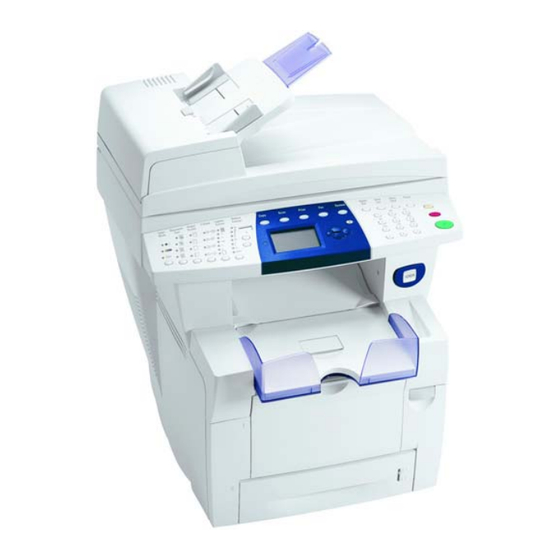
Page 14: Parts Of The 8860Mfp
Output Tray Exit Cover Control Panel Duplex Automatic Document Feeder (DADF) Front Cover DADF 10. Interface Cover 11. Drum Maintenance Kit and Waste Tray access 12. Front Door Latch Introduction Initial Issue 09/2007 Parts of the 8860MFP Phaser 8860/8860MFP Service Manual... - Page 15 The optional Hard Drive mounts on the rear panel. NOTE: When replacing the electronics module, transfer these components to the new module. • • Configuration Card • NVRAM Device • Hard Drive or Flash Disk Initial Issue Introduction 09/2007 Parts of the 8860MFP Phaser 8860/8860MFP Service Manual...
-
Page 16: 8860Mfp Control Panel Layout
Output Quality selects the output quality mode for copies: fast color, standard, enhanced, or high-resolution/photo. Phaser 8860/8860MFP products use a new formulation of Ink having unique properties. The Ink Loader on these products is keyed to accept this Ink shape only. The use of Ink not specif- 2-Sided selects either one or 2-sided for the original and one- or 2-sided for the output. - Page 17 Red indicates a startup or operational error condition. • Blinking indicates a warm-up or busy condition. NOTE: To enter Service Diagnostics, press the BACK and ? buttons before the Xerox logo stops scrolling and until Beginning Service Mode appears. Initial Issue...
-
Page 18: Parts Of The 8860
Control Panel • Hard Drive or Flash Disk Exit Cover Release Front Door Release Exit Cover Ink Loader 10. Output Tray Extension 11. Interface Cover 12. Side Door Introduction Initial Issue 09/2007 Parts of the 8860 xviii Phaser 8860/8860MFP Service Manual... - Page 19 Consumables CAUTION Phaser 8860/8860MFP products use a new formulation of Ink having unique properties. The Ink Loader on these products is keyed to accept this Ink shape only. The use of Ink not specif- ically designed for this product can result in system failures.
-
Page 20: 8860 Control Panel Layout
Printer goes to the ready state without waiting for temperatures to Ready) reach operating values. On power-up, when the Xerox splash screen displays, press and release the Up Arrow button, then press the Down Arrow button. If the printer detects ink on the drum, the display indicates a warming-up status. -
Page 21: 8860 Menu Map
8860 Menu Map NOTE: Maps vary by model. Figure 2 8860 Menu Map (2/2) Figure 1 8860 Menu Map (1/2) Initial Issue Introduction 09/2007 8860 Menu Map Phaser 8860/8860MFP Service Manual... -
Page 22: System Specifications
The DADF accommodates sizes from 114 x 140 mm (4.5 x 5.5 in.) to 216 x 356 mm (8.5 x 14.0 in.). The weight range includes 60-120 g/m2 (16-32 lb. Bond) (22-45 lb. Cover). Introduction Initial Issue 09/2007 System Specifications xxii Phaser 8860/8860MFP Service Manual... - Page 23 2 seconds (performed prior to copier and scan operations) Power Saver Mode Scanner and DADF are switched OFF. Also, lamps automati- cally turn off after 20 minutes. Initial Issue Introduction 09/2007 System Specifications Phaser 8860/8860MFP Service Manual xxiii...
- Page 24 The intensity and length of exposure to visible light on paper items should be reduced as much as possible. • Maintain constant temperatures and relative humidity • Avoid light, heat, and dampness. Introduction Initial Issue 09/2007 System Specifications xxiv Phaser 8860/8860MFP Service Manual...
- Page 25 On the Control Panel, press the System button. Select Information, and then press the OK button. Select Information Pages, and then press the OK button. Select Paper Tips, and then press the OK button to print. See also: Recommended Media List at www.xerox.com/paper Initial Issue Introduction 09/2007...
- Page 26 Introduction Initial Issue 09/2007 System Specifications xxvi Phaser 8860/8860MFP Service Manual...
- Page 27 1 Service Call Procedures Service Call Procedures....................Initial Actions ........................Routine Maintenance Activities ..................Cleaning Procedures....................... Final Actions........................Initial Issue Service Call Procedures 09/2007 Phaser 8860/8860MFP Service Manual...
- Page 28 Service Call Procedures Initial Issue 09/2007 Phaser 8860/8860MFP Service Manual...
-
Page 29: Service Call Procedures
5.5mm (magnetic) P/N 600T2123 Serial Adaptor Cable 600T80374 Network Cross-over cable Tech Scanner Calibration page P/N 109K01910 Toner Vac Toner and general cleaning Multimeter Volts, Ohms, Current Initial Issue Service Call Procedures 09/2007 Service Call Procedures Phaser 8860/8860MFP Service Manual... -
Page 30: Initial Actions
Try to duplicate the problem by running the same jobs that the customer ran once repairs are complete to verify repairs are effective. Go to General Procedures to further investigate the problem. Service Call Procedures Initial Issue 09/2007 Service Call Procedures, Initial Actions Phaser 8860/8860MFP Service Manual... -
Page 31: Routine Maintenance Activities
Clean the Document Cover. DADF Check the paper path for debris or damage. Clean the rolls with a clean cloth and Film Remover as required. Initial Issue Service Call Procedures 09/2007 Routine Maintenance Activities, Cleaning Proce- Phaser 8860/8860MFP Service Manual... -
Page 32: Final Actions
Issue copy credits as needed. Discuss the service call with the customer to ensure that the customer understands what has been done and is satisfied with the results of the service call. Service Call Procedures Initial Issue 09/2007 Final Actions Phaser 8860/8860MFP Service Manual... - Page 33 19,0XX.4x Printhead Calibration Faults ................2-32 19,0XX.6x Waveform Program Faults................2-33 21,000.69 Diagnostic Firmware Version Mismatch............2-33 22,0XX.6x Jam Fault....................... 2-34 23,0XX.6x NVRAM Faults....................2-34 23,133.4x RAM Faults..................... 2-35 Initial Issue Error Messages and Codes 09/2007 Phaser 8860/8860MFP Service Manual...
- Page 34 Error Messages and Codes Initial Issue 09/2007 Phaser 8860/8860MFP Service Manual...
-
Page 35: Power On Self Tests
For problems associated with an error message or code, see Error Message Control Panel is initialized. Troubleshooting. Troubleshooting tips are available at: www.xerox.com/support. The following table defines the blink patterns associated with a failure: Check the main menu for current data and historical error data. - Page 36 15.04 Flutter then 15 blinks Hard CPU interrupt error 15.05 Flutter then 15 blinks Hard CPU interrupt error 15.06 Flutter then 15 blinks Hard CPU interrupt error Error Messages and Codes Initial Issue 09/2007 Power On Self Tests Phaser 8860/8860MFP Service Manual...
-
Page 37: Nvram Reset
Transmission Report Color Balance -> Magenta Color Balance Starting Rate Super G3 Color Balance -> Yellow Color Balance Color Balance -> Black Color Balance Laser Original Prescan Glass Initial Issue Error Messages and Codes 09/2007 NVRAM Reset Phaser 8860/8860MFP Service Manual... - Page 38 Table 2 System Parameters Not Affected by an NVRAM Reset Custom Units Inches/mm No Parameter Comment Cleaning Page Source Highest Metric Defaults MAC Address Set by the Configuration Card Serial Number Model number Error Messages and Codes Initial Issue 09/2007 NVRAM Reset Phaser 8860/8860MFP Service Manual...
-
Page 39: Error Message Troubleshooting
NOTE: A CPU exception can either be caused by hardware or firmware error. Refer to the infoSMART Knowledge Base for descriptions of the most common faults. Initial Issue Error Messages and Codes 09/2007 NVRAM Reset, Error Message Troubleshooting Phaser 8860/8860MFP Service Manual... -
Page 40: 1,00X.4X 525-Sheet Feeder Faults
Does the Pick Clutch operate correctly? Test the Lift Motor. Run the Service Diagnostics Lift Motor test for the affected tray. Does the Lift Motor operate correctly? Error Messages and Codes Initial Issue 09/2007 1,00X.4x Phaser 8860/8860MFP Service Manual... -
Page 41: 1,000.6X 525-Sheet Feeder Program Faults
Replace the I/O between P/J840 on the I/O Board and the error persists, Board (REP 5.0.13). on the Electronics Module. replace the I/O Is the wiring defective? Board. Initial Issue Error Messages and Codes 09/2007 1,000.6x, 2,00X.xx Phaser 8860/8860MFP Service Manual... -
Page 42: 2,006.Xx I/O Board Program Faults
Does the problem persist? Does the problem persist? Check ground integrity. Replace the NVRAM Reconnect the sys- Are the system grounds connected? device (REP 5.0.9). tem grounds. Error Messages and Codes Initial Issue 09/2007 2,006.xx, 2,0XX.6x 2-10 Phaser 8860/8860MFP Service Manual... -
Page 43: 3,0Xx.6X Ipc Program Faults
Heaters tests with all heaters On. 5.0.5). Do the heaters function properly? Check the harness to the failed heater. Replace the har- Replace the failed Is the harness damaged? ness. component. Initial Issue Error Messages and Codes 09/2007 3,0XX.6x, 4,0xx.4x Phaser 8860/8860MFP Service Manual 2-11... -
Page 44: 4,024.42 Wiper Alignment Fault
Did the test fail? Run the Service Diagnostics Head Main- Exit Module Maintenance Clutch tenance Clutch test. Media Drive Assy (REP 4.0.4). Does the clutch function correctly? Wiper Blade Error Messages and Codes Initial Issue 09/2007 4,024.42, 4,025.46 2-12 Phaser 8860/8860MFP Service Manual... -
Page 45: 4,0Xx.6X Process Control Program Faults
Test Y-Axis Belt tension. Go to Step 6. Replace the Y-Axis Run the Service Diagnostics Y-Axis Belt Belt (REP 2.0.4). Tension test. Did the test pass? Initial Issue Error Messages and Codes 09/2007 4,0xx.6x, 5,0xx.4x Phaser 8860/8860MFP Service Manual 2-13... -
Page 46: 5,0Xx.6X Y-Axis Sub-System Program Faults
Does the problem persist? Check ground integrity. Reset NVRAM. If the Reconnect the sys- Are the system grounds connected? error persists, tem grounds. replace the NVRAM device (REP 5.0.9). Error Messages and Codes Initial Issue 09/2007 5,0xx.4x, 5,0xx.6x 2-14 Phaser 8860/8860MFP Service Manual... -
Page 47: 6,0Xx.4X X-Axis Fault
Does the problem persist? Check ground integrity. Reset NVRAM. If the Reconnect the sys- Are the system grounds connected? error persists, tem grounds. replace the NVRAM device (REP 5.0.9). Initial Issue Error Messages and Codes 09/2007 6,0xx.4x, 6,0xx.6x Phaser 8860/8860MFP Service Manual 2-15... -
Page 48: 7,002.44 Process Drive Fault
Do the Transfix Cam operate correctly? persists, replace the 7,010.xx fault codes. mended actions for Transfix Cam Shaft error codes and (REP 2.0.10). reboot the printer. Error Messages and Codes Initial Issue 09/2007 7,002.44, 7,006.4x 2-16 Phaser 8860/8860MFP Service Manual... -
Page 49: 7,007.49 Process Drive Fault
Test the Tilt Axis Drive. Go to Step 7. Replace the Pro- Run the Service Diagnostics Tilt Axis cess Drive (REP Drive test. 4.0.7). Did the test pass? Initial Issue Error Messages and Codes 09/2007 7,007.49, 7,008.41 Phaser 8860/8860MFP Service Manual 2-17... -
Page 50: 7,009.42 Printhead Restraint Fault
Test the Head Maintenance Clutch Go to Step 7. Replace the clutch Run the Service Diagnostics Head Main- (REP 4.0.4). tenance Wiper Clutch test. Does the clutch operate correctly? Error Messages and Codes Initial Issue 09/2007 7,008.41, 7,009.42 2-18 Phaser 8860/8860MFP Service Manual... -
Page 51: 7,01X.4X Process Faults
Does the error persist? Check the Printhead Lock Arms. Go to Step 3. Repair or replace the Do the arms rotate correctly? Printhead Restraints (REP 2.0.8). Initial Issue Error Messages and Codes 09/2007 7,009.42, 7,01X.4x Phaser 8860/8860MFP Service Manual 2-19... -
Page 52: 7,0Xx.6X Program Faults
Did the test pass? Test the Process Drive. Complete. Replace the Pro- Run the Service Diagnostics Process cess Drive (REP Motor test. 4.0.7). Does the Process Drive operate correctly? Error Messages and Codes Initial Issue 09/2007 7,01X.4x, 7,0xx.6x 2-20 Phaser 8860/8860MFP Service Manual... -
Page 53: 8,0Xx.4X Wiper Or Media Drive Faults
Media Drive. under the Printhead. Did this correct the problem? Is the Wiper, Media Drive, and Printhead clear or ink or obstructions? Initial Issue Error Messages and Codes 09/2007 8,0XX.4x Phaser 8860/8860MFP Service Manual 2-21... -
Page 54: 8,0Xx.6X Media Drive Program Faults
Does the problem persist? Check ground integrity. Reset NVRAM. If the Reconnect the sys- • Check that the Ink Sticks are genuine Xerox. Are the system grounds connected? error persists, tem grounds. • Check for obstructions in the Ink Wells. -
Page 55: 9,009.44 And 9,00X.6X Ink Loader Program Faults
Check ground integrity. Reset NVRAM. If the Reconnect the sys- Are the system grounds connected? error persists, tem grounds. replace the NVRAM device. (REP 5.0.9). Initial Issue Error Messages and Codes 09/2007 9,0XX.4x, 9,009.44 and 9,00X.6x Phaser 8860/8860MFP Service Manual 2-23... -
Page 56: 11,0Xx.xx Electronics Module Interface Faults
Left Side Harness (1/2) - Figure 6 Electronics Module, PL 5.0 Electronics Module - Figure 8 Optional Feeder, PL 3.0 Left Side Harness (1/2) - Figure 6 Error Messages and Codes Initial Issue 09/2007 11,0XX.xx 2-24 Phaser 8860/8860MFP Service Manual... -
Page 57: 11,100.60 Electronics Module Temperature Fault
Check that the air ducts are free of Replace the Elec- Replace the defec- 5.0.5). obstructions and the fans are operating tronics Module (REP tive fan. correctly. 5.0.5). Are the fans operating correctly? Initial Issue Error Messages and Codes 09/2007 11,100.60, 11,300.6x Phaser 8860/8860MFP Service Manual 2-25... -
Page 58: 12,000.60 Program Faults
Reseat all system connections to the Replace the Print- Complete. Printhead and check that the harnesses head (REP 2.0.2). are properly dressed. Does the error persist? Error Messages and Codes Initial Issue 09/2007 12,000.60, 13,000.48 2-26 Phaser 8860/8860MFP Service Manual... -
Page 59: 13,003.42 And 13,007.46 Thermal Faults
Does the fan operate correctly? Test the Electronics Module Fan. Go to Step 7. Replace the Elec- Does the Fan operate correctly? tronics Module Fan (REP 4.0.15). Initial Issue Error Messages and Codes 09/2007 13,003.42 and 13,007.46, 13,008.47 Phaser 8860/8860MFP Service Manual 2-27... -
Page 60: Drum Temp Sensor Faults
Check the Drum Heater Sensor harness. Replace the Drum Repair the wiring. Is the harness free from defects or dam- Temperature Sen- age? sor. (REP 6.0.4). Error Messages and Codes Initial Issue 09/2007 13,008.47, 13,067.43, 13,069.45, 13,071.47 2-28 Phaser 8860/8860MFP Service Manual... -
Page 61: 13,Xxx.4X Preheater Thermal Faults
2.0.2). Check Preheater connections and wiring. Replace the Pre- Repair or replace the undamaged? Are the connections secure and the wiring heater (REP 2.0.17). wiring. undamaged? Initial Issue Error Messages and Codes 09/2007 13,XXX.4x, 13,1XX.4x Phaser 8860/8860MFP Service Manual 2-29... -
Page 62: 13,2Xx.4X Right Jetstack Thermal Faults
Repair the wiring. Are the connections secure and the wiring head (REP 2.0.2). Are the connections secure and the wiring head (REP 2.0.2). undamaged? undamaged? Error Messages and Codes Initial Issue 09/2007 13,2XX.4x, 13,XXX.xx Printhead Reservoir 2-30 Phaser 8860/8860MFP Service Manual... -
Page 63: 13,Xxx.xx Ink Loader Thermal Faults
Electronics Module - Figure 8 I/O Board, PL 5.0 I/O Board (2/2) - Figure 12 Electronics Module, PL 5.0 Electronics Module - Figure 8 Right Combined Cable, PL 5.0 Initial Issue Error Messages and Codes 09/2007 13,XXX.xx Phaser 8860/8860MFP Service Manual 2-31... -
Page 64: 13,00X.6X Thermal Program Faults
Does the problem persist? the error persists, Are the system grounds connected? error persists, tem grounds. replace the Electron- replace the NVRAM ics Module (REP device (REP 5.0.9). 5.0.5). Error Messages and Codes Initial Issue 09/2007 13,00x.6x, 19,0XX.4x 2-32 Phaser 8860/8860MFP Service Manual... -
Page 65: 19,0Xx.6X Waveform Program Faults
Media Drive Motor and Y- replace the NVRAM Axis Assembly. Also check the ground clip device (REP 5.0.9). at the Tray 2 Pick Clutch. Are the system grounds connected? Initial Issue Error Messages and Codes 09/2007 19,0XX.6x, 21,000.69 Phaser 8860/8860MFP Service Manual 2-33... -
Page 66: 22,0Xx.6X Jam Fault
Check that the Pick Rollers are clean and in good condition. Troubleshooting Procedure Locate the code in the Jam Codes listing and follow the procedure, if available Error Messages and Codes Initial Issue 09/2007 22,0XX.6x, 23,0XX.6x 2-34 Phaser 8860/8860MFP Service Manual... -
Page 67: 23,133.4X Ram Faults
Go to Step 2. Complete. tronics Module. Does the problem persist? Replace SDRAM. Replace the Elec- Complete. Does the problem persist? tronics Module (REP 5.0.5 PL 5.1 (8860)). Initial Issue Error Messages and Codes 09/2007 23,133.4x, 26,0XX.6x Phaser 8860/8860MFP Service Manual 2-35... -
Page 68: 27,0Xx.6X Profile Library
Does the problem persist? Check ground integrity. Reset NVRAM. If the Reconnect the sys- Are the system grounds connected? error persists, tem grounds. replace the NVRAM device (REP 5.0.9). Error Messages and Codes Initial Issue 09/2007 27,0XX.6x, 29,0XX.6x 2-36 Phaser 8860/8860MFP Service Manual... -
Page 69: 31,001.40 Mechanical Initialization Jam
Repair or replace Remove the Media Drive Assembly and Drive Assembly rollers. check each roller for binding or drag. (REP 4.0.14). Do the rollers rotate correctly? Initial Issue Error Messages and Codes 09/2007 31,001.40, 31,0XX.6x Phaser 8860/8860MFP Service Manual 2-37... -
Page 70: 33,00X.4X Tray 1 Width Sensor Faults
Are the connections secure and the cable undamaged? Replace the Printhead (REP 2.0.2). Replace the Elec- Complete. Does the error persist? tronics Module (REP 5.0.5). Error Messages and Codes Initial Issue 09/2007 33,00X.4x, 34,00X.4x 2-38 Phaser 8860/8860MFP Service Manual... -
Page 71: 34,01X Ink Level Sense Faults
WARNING the initialization process immedi- Allow adequate time for the system to cool before servicing the printer. ately after the Xerox logo is replaced Initial Actions by the words “Warming Up” by hold- ing down the Up Arrow button while •... -
Page 72: 36,000.40 Drum Maintenance Faults
Test the Drum Maintenance drive. Complete. Replace the Pro- Run the Service Diagnostics Drum Main- cess Drive (REP tenance Drive test. 4.0.7) Does the drive operate correctly? Error Messages and Codes Initial Issue 09/2007 34,01X, 36,000.40 2-40 Phaser 8860/8860MFP Service Manual... -
Page 73: 36,001.67 Drum Maintenance Drive Faults
Replace the Pro- Run the Service Diagnostics Drum Main- Maintenance Pivot cess Drive (REP tenance Drive test. Plate and Shaft 4.0.7) Does the drive operate correctly? (REP 2.0.16). Initial Issue Error Messages and Codes 09/2007 36,001.67, 36,002.44 Phaser 8860/8860MFP Service Manual 2-41... -
Page 74: 37,0Xx.xx Pest Heater Faults
Does the affected component reach oper- ating temperature? Check wiring to the affected component. Repair or replace the Replace the affected Is the wiring damaged? harness. component. Error Messages and Codes Initial Issue 09/2007 37,0XX.xx, 37,01X.41 2-42 Phaser 8860/8860MFP Service Manual... -
Page 75: 37,016.43 Pest 50 Volt Supply Fault
Module (REP Unplug all connections to the Electronics 5.0.5). Module. Turn the system On. Do the PE and PS indicators (near the Power Switch) flash momentarily? Initial Issue Error Messages and Codes 09/2007 37,016.43 Phaser 8860/8860MFP Service Manual 2-43... -
Page 76: 37,0Xx.4X Pest Clutch/Solenoid Faults
Does the component operate correctly? Check wiring to the affected component. Repair or replace the Replace the affected Is the wiring damaged? harness. component. Error Messages and Codes Initial Issue 09/2007 37,0XX.4x, 37,024.48 2-44 Phaser 8860/8860MFP Service Manual... -
Page 77: 37,026.44 Pest Purge Pump Fault
Is the connection secure and the harness Check wiring to the affected component. Repair or replace the Replace the Relay undamaged? Is the wiring damaged? harness. Board (REP 5.0.19). Initial Issue Error Messages and Codes 09/2007 37,026.44, 37,02X.4x Phaser 8860/8860MFP Service Manual 2-45... -
Page 78: 37,03X.4X Pest X-Axis Motor Faults
Does the motor operate correctly? Check wiring to the motor. Repair or replace the Replace the Y-Axis Is the wiring damaged? harness. Motor (REP 4.0.11). Error Messages and Codes Initial Issue 09/2007 37,03X.4x, 37,035.44 and 37,036.45 2-46 Phaser 8860/8860MFP Service Manual... -
Page 79: 37,037.46 And 37,038.47 Pest Media Drive Faults
Does the motor operate correctly? Check wiring to the motor. Repair or replace the Replace the Pro- Is the wiring damaged? harness. cess Drive (REP 4.0.7). Initial Issue Error Messages and Codes 09/2007 37,037.46 and 37,038.47, 37,039.48 and 37,040.40 Phaser 8860/8860MFP Service Manual 2-47... -
Page 80: 37,0Xx.4X Pest Power Supply Faults
The troubleshooting table lists parts and wiring referenced in the troubleshooting procedure. Table 1 37,0XX.4x Troubleshooting Reference Table Applicable Parts Wiring and Plug/Jack References Electronics Module, PL 5.0 Error Messages and Codes Initial Issue 09/2007 37,0XX.4x 2-48 Phaser 8860/8860MFP Service Manual... -
Page 81: 39,002.40 And 39,003.41 Scanner Subsystem Test Faults
Complete. Go to Step 2. Does this correct the problem? Replace the Scanner Assembly (REP Complete. 1.0.11). Replace the Scanner Assembly (REP Complete. 1.0.11). Initial Issue Error Messages and Codes 09/2007 39,002.40 and 39,003.41, 39,004.42 Phaser 8860/8860MFP Service Manual 2-49... -
Page 82: 39,005.43 Scanner Missing Fault
With the Exit Module motors discon- Replace the DADF Go to Step 5. nected, disconnect the DADF from the (REP 1.0.15). Scanner. Does the Status LED stop blinking and remain On? Error Messages and Codes Initial Issue 09/2007 39,005.43 2-50 Phaser 8860/8860MFP Service Manual... -
Page 83: 39,010.8 Document Feeder Disconnected Or Missing
(REP 1.0.15). Complete. Does the problem persist? Cycle system power and retest. Complete. Replace the DADF Does this correct the problem? (REP 1.0.15). Initial Issue Error Messages and Codes 09/2007 39,010.8 , 39,011.40 and 39,012.40 Phaser 8860/8860MFP Service Manual 2-51... -
Page 84: 39,013.42 Document Feeder Jam
Does the problem persist? Remove all media, open and close the Complete. Replace the DADF DADF Front Cover, and retest. (REP 1.0.15). Does this correct the problem? Error Messages and Codes Initial Issue 09/2007 39,013.42 , 39,014.43 2-52 Phaser 8860/8860MFP Service Manual... -
Page 85: Jam Codes
Verify all doors and covers are fully closed and not moving during printing. Deskew flag sensor event during head purge. Deskew sensor in an unexpected state during a Transfix Roller oiling. Initial Issue Error Messages and Codes 09/2007 Jam Codes Phaser 8860/8860MFP Service Manual 2-53... - Page 86 Run the Paper Lead Edge Times test using Service Diagnostics. Check system grounds. Test the Deskew Clutch using Service Diagnostics. Replace the Stripper Carriage Assembly (REP 2.0.12), then retest. Error Messages and Codes Initial Issue 09/2007 Jam Codes 2-54 Phaser 8860/8860MFP Service Manual...
- Page 87 Check system grounds. Test the Exit Sensor using Service Diagnostics. Run the Paper Lead Edge Times test using Service Diagnostics. Replace the problem component, then retest. Initial Issue Error Messages and Codes 09/2007 Jam Codes Phaser 8860/8860MFP Service Manual 2-55...
- Page 88 (REP 4.0.11). Run the Voltages test, replace the Electronics Module if necessary (REP 5.0.5). Y-Axis motor event during imaging. Probably a software fault. Check system grounds. Error Messages and Codes Initial Issue 09/2007 Jam Codes 2-56 Phaser 8860/8860MFP Service Manual...
- Page 89 Run the Check Drum Y-Axis Encoder test. Remove the Preheater (REP 2.0.17), and check the Preheater flag for ink or paper interference. Replace the Preheater (REP 2.0.17). Initial Issue Error Messages and Codes 09/2007 Jam Codes Phaser 8860/8860MFP Service Manual 2-57...
- Page 90 Run the Monitor Sensors test using Service Diagnostics. Check the Paper Size Switch. Replace if necessary (REP 6.0.7). Replace the 525-Sheet Feeder. Replace the Pivot Arm. Replace the Pivot Arm. Error Messages and Codes Initial Issue 09/2007 Jam Codes 2-58 Phaser 8860/8860MFP Service Manual...
- Page 91 Check that the media guides are adjusted correctly. Run the Monitor Sensors test to test the Tray 4 Paper Size Switch. Replace the Tray 4 525-Sheet Feeder. Replace the pivot arm. Initial Issue Error Messages and Codes 09/2007 Jam Codes Phaser 8860/8860MFP Service Manual 2-59...
- Page 92 Error Messages and Codes Initial Issue 09/2007 Jam Codes 2-60 Phaser 8860/8860MFP Service Manual...
- Page 93 IQ33 Image is Offset or Cut-Off ..................3-24 IQ34 Poor Ink Adhesion, Poor Image Durability ............. 3-25 IQ35 Massive Jet Loss ....................3-25 Analyzing Service Test Prints ..................3-26 Jet Substitution Mode...................... 3-31 Initial Issue Image Quality 09/2007 Phaser 8860/8860MFP Service Manual...
- Page 94 Image Quality Initial Issue 09/2007 Phaser 8860/8860MFP Service Manual...
-
Page 95: Iq1 Iot Image Quality Entry Rap
Table 2 Scanner Image Quality Problems Symptom Dark Streaks on the Scanned Image Skewed Scan Image Scanned Image is Lighter or Darker than the Original IQ10 Scan Image Colors Do Not Match Original IQ11 Initial Issue Image Quality 09/2007 Phaser 8860/8860MFP Service Manual... -
Page 96: Iq2 Dark Streaks On Copied Image
(ADJ 1.15.1). Does the problem persist? Replace the DADF (REP 1.0.15). Replace the Complete. Does the problem persist? Scanner Assem- (REP 1.0.11). Figure 1 DADF Calibration Strip Image Quality Initial Issue 09/2007 IQ2, IQ3 Phaser 8860/8860MFP Service Manual... -
Page 97: Iq4 Skewed Copy Image
Does the problem persist? Scan a copy of the page printed in Step 2. Replace the Scan- Replace the DADF Does the problem persist? ner Assembly (REP 1.0.15). (REP 1.0.11). Initial Issue Image Quality 09/2007 IQ4, IQ6 Phaser 8860/8860MFP Service Manual... -
Page 98: Iq5 Copy Image Is Lighter Or Darker Than The Original
Replace the Scan- Replace the Elec- Print Engine. ner Assembly tronics Module. If Is the cabling damaged? (REP 1.0.11). the problem per- sists, replace the Scanner Assem- (REP 1.0.11). Image Quality Initial Issue 09/2007 IQ5, IQ7 Phaser 8860/8860MFP Service Manual... -
Page 99: Iq8 Dark Streaks On Copied Image
Perform the DADF to Scanner Calibration Replace the Scan- Complete. adjustment procedure (ADJ 1.15.1). (REP 1.0.11). adjustment procedure (ADJ 1.15.1). ner Assembly Does the problem persist? Does the problem persist? (REP 1.0.11). Initial Issue Image Quality 09/2007 IQ8, IQ9 Phaser 8860/8860MFP Service Manual... -
Page 100: Iq10 Copy Image Is Lighter Or Darker Than The Original
Replace the Scan- Replace the Elec- Print Engine. ner Assembly tronics Module Is the cabling damaged? (REP 1.0.11). (REP 5.0.5). If the problem persists, replace the Scan- ner Assembly. Image Quality Initial Issue 09/2007 IQ10, IQ11 Phaser 8860/8860MFP Service Manual... -
Page 101: Iq12 Fuzzy Text Or Image
Scan a copy of the page printed in Step 2. Replace the Scan- Replace the DADF Does the problem persist? ner Assembly (REP 1.0.15). (REP 1.0.11). Figure 2 Discolored Jets on the Light Stripes Page Initial Issue Image Quality 09/2007 IQ12, IQ13 Phaser 8860/8860MFP Service Manual... -
Page 102: Iq14 Predominate Light Stripes
Air bubbles can be ingested into the Printhead as a result of a strong shock, such as a tray slam, or during ink cooling and solidification. Image Quality Initial Issue 09/2007 IQ13, IQ14 3-10 Phaser 8860/8860MFP Service Manual... -
Page 103: Iq15 Smudges Or Smears
Check the Drum Maintenance Pivot Plate and Replace the Pre- Complete Cam Rollers for damage or debris. heater (REP Replace any defective parts. 2.0.17). Does the problem persist? Initial Issue Image Quality 09/2007 IQ15, IQ16 Phaser 8860/8860MFP Service Manual 3-11... -
Page 104: Iq17 No Image Is Printed
5.0.5). If the Figure 1 Example of Uneven or Incorrect Color Output Does the problem persist? problem persists, replace the Print- NOTE: Using non-Xerox ink may cause unpredictable color results. head (REP 2.0.2). Initial Actions Check that supported media is being used. -
Page 105: Iq19 Streaks Or Lines Down The Print
Complete. Drum Maintenance Kit, Printhead and the Stripper Blade to see that nothing is in con- tact with the Drum. Clean the Stripper Blade. Does the problem persist? Initial Issue Image Quality 09/2007 IQ18, IQ19 Phaser 8860/8860MFP Service Manual 3-13... -
Page 106: Iq20 Scratches Or Marks Parallel To The Long Axis Of Printing
Does the problem persist? sists, go to Step 3. Using transparency media, print from Tray 1. Go to Step 4. Go to Step 5. Does the problem persist? Image Quality Initial Issue 09/2007 IQ19, IQ20 3-14 Phaser 8860/8860MFP Service Manual... -
Page 107: Iq21 Ink On The White Portion Of The Printed Page
Does the problem persist? sists, go to Step 3. Clean the Stripper Blade. Go to Step 4. Complete. Run the Service Diagnostics Remove Print Smears routine. Does the problem persist? Initial Issue Image Quality 09/2007 IQ20, IQ21 Phaser 8860/8860MFP Service Manual 3-15... -
Page 108: Iq22 Fuzzy Text
Try printing using a smoother, higher quality Go to Step 2. Complete. paper, some recycled papers are too coarse. Watermarked or punched paper could also cause latent images. Does the problem persist? Image Quality Initial Issue 09/2007 IQ21, IQ22 3-16 Phaser 8860/8860MFP Service Manual... -
Page 109: Iq23 Poor Primary Color Fill
Test the Y-Axis Encoder. Replace the Drum Complete. Run the Service Diagnostics Encoder test. Assembly (REP Does the problem persist? 2.0.3). If the prob- lem persists, go to Step 3. Initial Issue Image Quality 09/2007 IQ22, IQ23 Phaser 8860/8860MFP Service Manual 3-17... -
Page 110: Iq24 Ghosting
Transfix Roller ghosting is inherent to the sys- tem. This type of ghosting is most pro- nounced on the first 2-sided print. Ghosting should fade on subsequent prints. Does the problem persist? Image Quality Initial Issue 09/2007 IQ23, IQ24 3-18 Phaser 8860/8860MFP Service Manual... -
Page 111: Iq25 Poor Small Text Resolution
Does the problem persist? sists, got to Step 3. Check the X-Axis Drive installation and lubri- Replace the X-Axis Complete. cation? Motor (REP 4.0.5). Does the problem persist? Initial Issue Image Quality 09/2007 IQ24, IQ25 Phaser 8860/8860MFP Service Manual 3-19... -
Page 112: Iq26 Vertical Lines Appear Wavy
Clean the Stripper Blade and Exit Guides. Go to Step 5. Complete. Run the Service Diagnostics Drum Mainte- found. Does the problem persist? nance tests. Does the problem persist? Image Quality Initial Issue 09/2007 IQ26, IQ27 3-20 Phaser 8860/8860MFP Service Manual... -
Page 113: Iq28 Incomplete Image Transfer
Run the Service Diagnostics Drum tempera- Temperature Sen- ture tests. (REP 6.0.4). If Check the Drum Temperature Sensor. the problem per- Does the problem persist? sists, go to Step 3. Initial Issue Image Quality 09/2007 IQ27, IQ28 Phaser 8860/8860MFP Service Manual 3-21... -
Page 114: Iq29 Ink Smears On First Side Of Duplex Print
Replace the Pre- Complete. Run the Service Diagnostics Preheater tests. heater (REP Does the problem persist? 2.0.17). If the prob- lem persists, replace the Elec- tronics Module (REP 5.0.5). Image Quality Initial Issue 09/2007 IQ28, IQ29 3-22 Phaser 8860/8860MFP Service Manual... -
Page 115: Iq30 Repeating Print Defects
X posi- Assembly (REP motion of the Printhead? tion indicates a defect on the Drum. 2.0.3). Does the problem persist? Clean the Drum. Does the problem persist? Initial Issue Image Quality 09/2007 IQ30, IQ31 Phaser 8860/8860MFP Service Manual 3-23... -
Page 116: Iq32 Wrinkling
Kit. Does the problem persist? Check the Transfix components. Replace in this order: Complete. Does the problem persist? Transfix Roller Transfix Camshaft Transfix Load Arms Transfix Load Module Image Quality Initial Issue 09/2007 IQ32, IQ33 3-24 Phaser 8860/8860MFP Service Manual... -
Page 117: Iq34 Poor Ink Adhesion, Poor Image Durability
Inspect the Printhead for Ink overflow, blockage of the Purge Hose, or accumulations of ink underneath the Printhead. Procedure If ink has been overflowing the Printhead reserviors, replace the Printhead. Initial Issue Image Quality 09/2007 IQ34, IQ35 Phaser 8860/8860MFP Service Manual 3-25... -
Page 118: Analyzing Service Test Prints
Turn the system off for 4 to 6 hours (or overnight, if practical). Then perform a clean/purge cycle again. There may be a problem in the Purge Pump assembly or the wiper assembly may not be compliant. Verify that the printer is using Xerox ink. Follow the instructions on the “Printhead Troubleshooting Checklist”. - Page 119 Some print artifacts visible on the print do not show when projected. Like- wise, some defects do not show until projected. Causes: Confirm that you are using the transparency that is supported for this system. Clean or replace the paper release blade. Initial Issue Image Quality 09/2007 Phaser 8860/8860MFP Service Manual 3-27...
- Page 120 This print is used by manufacturing and Engineering only. Paper Path This print is used by Manufacturing and Engineering only. Head to Drum Check These prints indicate if the gap between the printhead and the drum is correct. Image Quality Initial Issue 09/2007 3-28 Phaser 8860/8860MFP Service Manual...
- Page 121 These prints can be used to determine if the drum or Transfix Roller have a defect. Drum defects do not move in the X-position print-to-print; but it does move into the Y-position print-to-print; drum defects do not repeat down the page. Initial Issue Image Quality 09/2007 Phaser 8860/8860MFP Service Manual 3-29...
- Page 122 This page is automatically printed following a purge. It is used to flush the jet nozzles of any possible contamination or color mixed jets. It can also be printed on its own. Image Quality Initial Issue 09/2007 3-30 Phaser 8860/8860MFP Service Manual...
-
Page 123: Jet Substitution Mode
Saved & Stored jobs stored on the hard drive will not print correctly because they were ren- dered before the Jet Substitution was made. Figure 11 Cleaning Page Figure 1 Jet Substitution Exceptions Initial Issue Image Quality 09/2007 Jet Substitution Mode Phaser 8860/8860MFP Service Manual 3-31... - Page 124 Scroll to Turn Jet Substitution Mode Off, and then press OK. Print the Eliminate Light Stripes Test page to verify that Substitution Mode is disabled for all jets. Image Quality Initial Issue 09/2007 Jet Substitution Mode 3-32 Phaser 8860/8860MFP Service Manual...
- Page 125 REP 3.0.18 Pick and Retard Rollers ................4-48 REP 3.1.13 Exit Module (8860)..................4-49 REP 4.0.3 Scanner Power Supply Fan (8860MFP) ............4-50 REP 4.0.4 Head Maintenance Clutch ................4-50 REP 4.0.5 X-Axis Motor ....................4-51 Initial Issue Repairs and Adjustments 09/2007 Phaser 8860/8860MFP Service Manual...
- Page 126 Repairs and Adjustments Initial Issue 09/2007 Phaser 8860/8860MFP Service Manual...
-
Page 127: Disassembly Overview
Plastic refers to a metal, self-tapping screw used to secure parts onto plastic. Metal refers to metal, fine-threaded screws used to secure parts onto metal. Figure 1 Procedural System Orientation Initial Issue Repairs and Adjustments 09/2007 Disassembly Overview Phaser 8860/8860MFP Service Manual... - Page 128 2. Removal procedures include dimensional specifications for screws being removed. CAUTION Many parts are secured by plastic tabs or hooks. Do not over Flex or force these parts. Repairs and Adjustments Initial Issue 09/2007 Disassembly Overview Phaser 8860/8860MFP Service Manual...
-
Page 129: Rep 1.0.1 Front Door / Tray 1 Assembly
Release the wiring from cable retainers. Remove the Front Door (Tray 1/MPT) by releasing the left hinge pin from the frame and sliding the door to the right. Initial Issue Repairs and Adjustments 09/2007 REP 1.0.1, REP 1.0.6 Phaser 8860/8860MFP Service Manual... -
Page 130: Rep 1.0.7 Left Side Cover (8860Mfp)
Pull outward on the front of the cover to release it from the frame. Replacement Insert the 3 tabs along the bottom edge of the cover into the slots in the frame before snapping the cover into place. Repairs and Adjustments Initial Issue 09/2007 REP 1.0.6, REP 1.0.7 Phaser 8860/8860MFP Service Manual... -
Page 131: Rep 1.0.8 Scanner Hinges (8860Mfp)
Slide the Scanner towards the back, and then lift to remove it from the printer. Remove the 4 (plastic T-20) screws that secure each hinge to the assembly. Initial Issue Repairs and Adjustments 09/2007 REP 1.0.8 Phaser 8860/8860MFP Service Manual... -
Page 132: Rep 1.0.9 Control Panel (8860Mfp)
NOTE: Failure to adequately secure the Scanner cable connection to the Rear Panel can result in sporadic Scanner errors. Seat the Scanner connector completely using the connector’s two thumbscrews. Repairs and Adjustments Initial Issue 09/2007 REP 1.0.9, REP 1.0.11 Phaser 8860/8860MFP Service Manual... -
Page 133: Rep 1.0.13 Dadf Front Cover (8860Mfp)
Remove 3 (plastic, T-20) screws that secure the DADF Front Cover. Figure 1 DADF Front Cover Fasteners Close and latch the DADF Input Chute. Figure 2 DADF Front Cover Removal Lift the DADF Front Cover to remove. Initial Issue Repairs and Adjustments 09/2007 REP 1.0.13 Phaser 8860/8860MFP Service Manual... -
Page 134: Rep 1.0.15 Duplex Automatic Document Feeder (8860Mfp)
NOTE: Failure to adequately secure the DADF cable connection to the Scanner Assembly can result in sporadic DADF errors. Seat the DADF connector completely using the connector’s two thumbscrews. Repairs and Adjustments Initial Issue 09/2007 REP 1.0.15, REP 1.0.19 4-10 Phaser 8860/8860MFP Service Manual... -
Page 135: Rep 1.0.20 Rear Cover (8860Mfp)
Insert the 3 tabs, located along the bottom edge of the cover, into the slots provided in the frame before snapping the cover into place. Initial Issue Repairs and Adjustments 09/2007 REP 1.0.20, REP 1.0.21 Phaser 8860/8860MFP Service Manual 4-11... -
Page 136: Rep 1.1.5 Control Panel Cover (8860)
CAUTION Figure 1 Removing the Control Panel Cover Use care during reassembly to avoid damaging the connections on the underside of of the Control Panel. Repairs and Adjustments Initial Issue 09/2007 REP 1.1.5, REP 1.1.6 4-12 Phaser 8860/8860MFP Service Manual... -
Page 137: Rep 1.1.7 Exit Cover (8860)
Transfer the Ink Sticks to the replacement Ink Loader. the Exit Cover before inserting the cover hinge pins into the pivot points in the printer frame. Initial Issue Repairs and Adjustments 09/2007 REP 1.1.7, REP 1.1.8 Phaser 8860/8860MFP Service Manual 4-13... -
Page 138: Rep 1.1.9 Left Side Cover (8860)
Pull forward to release the tab located near the AC connection and release the front tab while pulling outward at the top. Figure 1 Removing the Left Side Cover Figure 1 Removing the Right Side Cover Repairs and Adjustments Initial Issue 09/2007 REP 1.1.9, REP 1.1.10 4-14 Phaser 8860/8860MFP Service Manual... -
Page 139: Rep 2.0.1 Ink Loader (8860Mfp)
Ink Loader to remove the Ink Loader. Replacement Perform these steps while replacing the Ink Loader. Raise the Media Path Elevator before inserting the assembly. Initial Issue Repairs and Adjustments 09/2007 REP 2.0.1 Phaser 8860/8860MFP Service Manual 4-15... -
Page 140: Rep 2.0.2 Printhead
(REP 2.0.1). Place several sheets of paper between the Printhead and Drum to protect the Drum. Unlock the Printhead Wiper Assembly by raising the Lock. Repairs and Adjustments Initial Issue 09/2007 REP 2.0.1, REP 2.0.2 4-16 Phaser 8860/8860MFP Service Manual... - Page 141 Figure 2 Lowering the Printhead Wiper Assembly Move the Printhead Tilt Spring from its position on the Printhead and hook it behind itself as shown in Figure Initial Issue Repairs and Adjustments 09/2007 REP 2.0.2 Phaser 8860/8860MFP Service Manual 4-17...
- Page 142 12. Remove the left and right Printhead Restraints. To remove the restraints, remove 1 (plas- tic, T-20) screw that secures each restraint, and then shift the restraint inwards toward the Printhead while lifting toward the rear of the printer. Repairs and Adjustments Initial Issue 09/2007 REP 2.0.2 4-18 Phaser 8860/8860MFP Service Manual...
- Page 143 P/J3 and free the harness from the restraint. Figure 6 Removing the Printhead Restraints 13. Remove the Roll Block on the left end of the Printhead Shaft. Initial Issue Repairs and Adjustments 09/2007 REP 2.0.2 Phaser 8860/8860MFP Service Manual 4-19...
- Page 144 Figure Figure 9 Printhead Cradle Notch Location NOTE: Unlock the connectors before disconnecting the ribbon cables. Repairs and Adjustments Initial Issue 09/2007 REP 2.0.2 4-20 Phaser 8860/8860MFP Service Manual...
- Page 145 11. Set the X-Axis Bias Hook and spring on the left end of the Printhead Shaft. See Figure Ensure the point of the hook is centered in the shaft and the rest of the hook floats freely. Initial Issue Repairs and Adjustments 09/2007 REP 2.0.2 Phaser 8860/8860MFP Service Manual 4-21...
-
Page 146: Rep 2.0.3 Drum Assembly
Figure 1 Drum Fan Mounting Ground Plate behind the fan 15. Unplug the Drum Heater Harness P/J200 from the Relay Board and free the harness from the retaining hook. Repairs and Adjustments Initial Issue 09/2007 REP 2.0.3 4-22 Phaser 8860/8860MFP Service Manual... - Page 147 Drum Assembly and torque the screw to 25 in.-lbs. Install the remaining (metal, T-20) screws and washers into the left side of the Drum Assembly and torque to 25 in.-lbs. Initial Issue Repairs and Adjustments 09/2007 REP 2.0.3 Phaser 8860/8860MFP Service Manual 4-23...
- Page 148 13. Inset and torque to 12 in-lbs. the 6 Exit Module screws. On 8860 models, the Exit Module is secured with 4 screws torqued to 12 in-lbs. Figure 4 8860MFP Exit Module Right Side Fasteners Repairs and Adjustments Initial Issue 09/2007 REP 2.0.3 4-24 Phaser 8860/8860MFP Service Manual...
- Page 149 27. Reposition the Media Drive Assembly and seat the roller shafts. Insert the 6 (plastic, T-20) screws, and torque the screws to 12 in-lbs. 28. Install the Ink Loader. 29. Install the Lower Duplex Guide. 30. Install the Preheater. Initial Issue Repairs and Adjustments 09/2007 REP 2.0.3 Phaser 8860/8860MFP Service Manual 4-25...
-
Page 150: Rep 2.0.4 Y-Axis Belt
38. Turn system power On and print a Configuration page to test operation. Figure 1 Removing the Y-Axis Belt Hold tension with one hand while removing the Y-Axis Belt with the other. Repairs and Adjustments Initial Issue 09/2007 REP 2.0.3, REP 2.0.4 4-26 Phaser 8860/8860MFP Service Manual... -
Page 151: Rep 2.0.5 Printhead Wiper Blade And Wiper Belt
Perform the Head Tilt Gear Homing procedure (ADJ 4.13.1). Perform the Process Drive Homing Procedure (ADJ 4.7.1). Turn system power On to check wiper operation. Figure 1 Removing the Printhead Wiper Initial Issue Repairs and Adjustments 09/2007 REP 2.0.5 Phaser 8860/8860MFP Service Manual 4-27... -
Page 152: Rep 2.0.7 Purge Pressure Pump
Place several sheets of paper between the Printhead and Drum to protect the Drum. Unlock the Wiper Assembly by raising the Wiper Assembly Lock. Figure 1 Removing the Purge Pressure Pump Figure 1 Releasing the Printhead Restraints Repairs and Adjustments Initial Issue 09/2007 REP 2.0.7, REP 2.0.8 4-28 Phaser 8860/8860MFP Service Manual... - Page 153 Figure 2 Lowering the Printhead Wiper Blade Hold the Printhead away from the Drum and push down on the left and right Printhead Restraint Arms to release the Printhead Tilt Spring tension. Initial Issue Repairs and Adjustments 09/2007 REP 2.0.8 Phaser 8860/8860MFP Service Manual 4-29...
- Page 154 12. Remove 1 (plastic, T-20) screw that secures each Printhead Restraint, and then shift the restraint inwards toward the Printhead while lifting toward the rear of the printer. Figure 6 Removing the Printhead Restraints Repairs and Adjustments Initial Issue 09/2007 REP 2.0.8 4-30 Phaser 8860/8860MFP Service Manual...
-
Page 155: Rep 2.0.10 Transfix Camshaft
Slide the camshaft to the right, making sure the bearing slides over to the gear. Move the camshaft down and slightly to the right, and then up to the left to remove it from the chas- sis. Initial Issue Repairs and Adjustments 09/2007 REP 2.0.8, REP 2.0.10 Phaser 8860/8860MFP Service Manual 4-31... -
Page 156: Rep 2.0.11 Drum Maintenance Camshaft
1. Align the hole in the white Head Tilt Gear with the arrow on the chassis to put the Head Tilt Gear in home position. Repairs and Adjustments Initial Issue 09/2007 REP 2.0.10, REP 2.0.11 4-32 Phaser 8860/8860MFP Service Manual... -
Page 157: Rep 2.0.12 Stripper Carriage Assembly
Loosen 1 (plastic, T-20) screw that secures an I/O Board ground strap and the Transfix Roller Shaft Restraint, then remove the restraint. Initial Issue Repairs and Adjustments 09/2007 REP 2.0.11 , REP 2.0.12 Phaser 8860/8860MFP Service Manual 4-33... -
Page 158: Rep 2.0.13 Transfix Roller
NOTE: Make sure the I/O Board Ground Straps are properly positioned and the I/O Board is behind the chassis retainers before installing the 2 I/O Board screws. Repairs and Adjustments Initial Issue 09/2007 REP 2.0.12, REP 2.0.13 4-34 Phaser 8860/8860MFP Service Manual... - Page 159 Carriage Assembly. 11. Lift the Stripper Carriage Assembly and Transfix Roller up and out of the chassis. 12. Remove the Transfix Roller from the Stripper Carriage Assembly. Initial Issue Repairs and Adjustments 09/2007 REP 2.0.13 Phaser 8860/8860MFP Service Manual 4-35...
-
Page 160: Rep 2.0.14 Y-Axis Spring
Remove the Y-Axis Spring using either a spring hook or pliers, Brace the printer to prevent Shaft, and the 2 Transfix Load Arms are removed as a single assembly. movement while removing the spring. Repairs and Adjustments Initial Issue 09/2007 REP 2.0.14, REP 2.0.15 4-36 Phaser 8860/8860MFP Service Manual... - Page 161 Figure 2 Removing the Transfix Load Arm Clevis Pins 12. Disconnect the Preheater Lift Solenoid P/J202 from the harness. 13. Remove the screw that secures the Preheater Lift Solenoid to the Transfix Load Module. Initial Issue Repairs and Adjustments 09/2007 REP 2.0.15 Phaser 8860/8860MFP Service Manual 4-37...
- Page 162 The Transfix Load Module fits tightly in the chassis. Some force is needed to remove it. Figure 6 Removing the Transfix Load Module Repairs and Adjustments Initial Issue 09/2007 REP 2.0.15 4-38 Phaser 8860/8860MFP Service Manual...
-
Page 163: Rep 2.0.16 Drum Maintenance Pivot Plate
Remove the KL- Clip on the right end of the shaft and remove the shaft from the chassis by pulling it out from the right side, Figure 1 Removing the Pivot Plate Shaft Initial Issue Repairs and Adjustments 09/2007 REP 2.0.15, REP 2.0.16 Phaser 8860/8860MFP Service Manual 4-39... -
Page 164: Rep 2.0.17 Preheater And Deskew Assembly
Slide the latches in and forward to release the Preheater as shown in Figure Head Tilt Gear (ADJ 4.13.1), and Process Drive Alignment (ADJ 4.7.1) adjustments before restoring system power Repairs and Adjustments Initial Issue 09/2007 REP 2.0.16, REP 2.0.17 4-40 Phaser 8860/8860MFP Service Manual... -
Page 165: Rep 2.0.21 X-Axis Bias Spring
Do not rotate the spring more than one-quarter turn. Perform the Head Tilt Gear (ADJ 4.13.1), and Process Drive Alignment (ADJ 4.7.1) adjustments before restoring system power. Initial Issue Repairs and Adjustments 09/2007 REP 2.0.17, REP 2.0.21 Phaser 8860/8860MFP Service Manual 4-41... -
Page 166: Rep 2.0.22 Preheater Lift Solenoid
Position the fingers on the Inner Simplex Guide over the segmented roller. Install the guide by snapping the left side to the retaining post, then the right side. Figure 1 Removing the Preheater Solenoid Repairs and Adjustments Initial Issue 09/2007 REP 2.0.22, REP 3.0.1 4-42 Phaser 8860/8860MFP Service Manual... -
Page 167: Rep 3.0.2 Lower Duplex Guide
Rotate the shaft forward, and then remove it to the right. Figure 1 Removing the Lower Duplex Guide Initial Issue Repairs and Adjustments 09/2007 REP 3.0.2, REP 3.0.3 Phaser 8860/8860MFP Service Manual 4-43... -
Page 168: Rep 3.0.4 Duplex Roller
Figure 1 Removing the Duplex Roller Figure 1 Removing the Take Away Roller Repairs and Adjustments Initial Issue 09/2007 REP 3.0.3 , REP 3.0.4 4-44 Phaser 8860/8860MFP Service Manual... -
Page 169: Rep 3.0.5 Upper Duplex Guide And Solenoid
Disconnect the solenoid (P/J250) from the I/O Board and release the harness from the right side retainers to remove the guide from the printer. Figure 1 Removing the Upper Duplex Guide Initial Issue Repairs and Adjustments 09/2007 REP 3.0.5 Phaser 8860/8860MFP Service Manual 4-45... -
Page 170: Rep 3.0.6 Outer Duplex Guide
Remove the 4 (plastic, T-20) screws that secure the Outer Duplex Guide. Figure 1 Removing the Outer Duplex Guide Figure 1 Exit Module Right Side Fasteners Repairs and Adjustments Initial Issue 09/2007 REP 3.0.6, REP 3.0.7 4-46 Phaser 8860/8860MFP Service Manual... - Page 171 Head Maintenance Clutch (P/J130). Replacement • I/O Board connector (P/J680). Transfer the Front Exit Module Harness to the replacement part, and Perform ADJ 2.5.1 after replacing the Exit Module. Initial Issue Repairs and Adjustments 09/2007 REP 3.0.7 Phaser 8860/8860MFP Service Manual 4-47...
-
Page 172: Rep 3.0.14 System Stabilizer
Figure 1 Removing the System Stabilizer Figure 1 Replacing the Pick Roller Lift the Retard Roller to vertical, then pull the roller from the shaft in the tray. See Figure Repairs and Adjustments Initial Issue 09/2007 REP 3.0.14, REP 3.0.18 4-48 Phaser 8860/8860MFP Service Manual... -
Page 173: Rep 3.1.13 Exit Module (8860)
Seat the Exit Module on the chassis., torque the 4 screws to 15 in. lbs, and perform 2.5.1. The system may report error 7,009.4x if the Wiper Assembly is misaligned. Initial Issue Repairs and Adjustments 09/2007 REP 3.0.18, REP 3.1.13 Phaser 8860/8860MFP Service Manual 4-49... -
Page 174: Rep 4.0.3 Scanner Power Supply Fan (8860Mfp)
Figure 1 Removing the Scanner Power Supply Fan Replacement NOTE: Route the fan harness behind the mylar insulator as shown in Figure Figure 1 Removing the Head Maintenance Clutch Repairs and Adjustments Initial Issue 09/2007 REP 4.0.3, REP 4.0.4 4-50 Phaser 8860/8860MFP Service Manual... -
Page 175: Rep 4.0.5 X-Axis Motor
Perform the Head Tilt Gear (ADJ 4.13.1), and Process Drive Alignment (ADJ 4.7.1) adjustments before restoring system power. Initial Issue Repairs and Adjustments 09/2007 REP 4.0.4, REP 4.0.5 Phaser 8860/8860MFP Service Manual 4-51... -
Page 176: Rep 4.0.6 Drum Fan
Remove 3 (plastic, T-20) screws that secure the Process Drive to the chassis. Figure 1 Removing the Drum Fan Replacement NOTE: Check that the grounding strap contacts the Pivot Plate Shaft following installation. Repairs and Adjustments Initial Issue 09/2007 REP 4.0.6, REP 4.0.7 4-52 Phaser 8860/8860MFP Service Manual... - Page 177 Figure 1 Removing the Process Drive and Process Drive Gear Alignment Remove the Process Drive from the chassis. Disconnect the Process Drive from the harness. Initial Issue Repairs and Adjustments 09/2007 REP 4.0.7 Phaser 8860/8860MFP Service Manual 4-53...
-
Page 178: Rep 4.0.8 Exit Roller Motor (8860Mfp)
This state is indicated by the LED on the Exit Module Control Board flashing and media jams in the Exit Module. Repairs and Adjustments Initial Issue 09/2007 REP 4.0.8, REP 4.0.9 4-54 Phaser 8860/8860MFP Service Manual... -
Page 179: Rep 4.0.10 Tray 2 Lift Motor Gear
Push Nut so the fingers point away from the shaft. Place a 3/8 in. nut driver over the nut and press firmly to seat the nut on the shaft. Figure 1 Removing the Y-Axis Spring Initial Issue Repairs and Adjustments 09/2007 REP 4.0.10, REP 4.0.11 Phaser 8860/8860MFP Service Manual 4-55... - Page 180 Check that the grounding lugs are captured by the screws, the spacers are present, and wiring 10. Release the harness from the retainers in the chassis. is correctly routed. Repairs and Adjustments Initial Issue 09/2007 REP 4.0.11 4-56 Phaser 8860/8860MFP Service Manual...
-
Page 181: Rep 4.0.12 Tray 1 Pick Solenoid
Figure 1 Removing the Tray 1 Pick Solenoid Replacement Align the hole in the solenoid with the boss on the Media Drive Assembly before tightening the screw. Initial Issue Repairs and Adjustments 09/2007 REP 4.0.12, REP 4.0.13 Phaser 8860/8860MFP Service Manual 4-57... -
Page 182: Rep 4.0.14 Media Drive Assembly
Push Nut so the fingers point away from the shaft. Place a 3/8 in. nut driver over the nut and press firmly to seat the nut on the shaft. Repairs and Adjustments Initial Issue 09/2007 REP 4.0.13, REP 4.0.14 4-58 Phaser 8860/8860MFP Service Manual... - Page 183 Pick Clutch. Next, working upwards, rotate the Duplex Feed Roller until the Duplex Roller Shaft seats in it’s clutch. Check that the Media Drive Assembly is correctly positioned before tightening the screws. Initial Issue Repairs and Adjustments 09/2007 REP 4.0.14 Phaser 8860/8860MFP Service Manual 4-59...
-
Page 184: Rep 4.0.15 Electronics Module Cooling Fan
Remove the X-Axis Spring (REP 2.0.21). Remove 1 (metal, T-20) screw that secures the X-Axis Spring Retainer to the chassis. Figure 1 Removing the Electronics Module Cooling Fan Repairs and Adjustments Initial Issue 09/2007 REP 4.0.15, REP 4.0.16 4-60 Phaser 8860/8860MFP Service Manual... - Page 185 Replace the spring. Turn the Head Tilt Gear while inserting the spring to guide the spring to its proper position behind the gear. Figure 3 Removing the Waste Tray Cover Initial Issue Repairs and Adjustments 09/2007 REP 4.0.16 Phaser 8860/8860MFP Service Manual 4-61...
-
Page 186: Rep 4.0.18 Fax Speaker (8860Mfp)
Replace the KL-Clip on the end of the Head Tilt Gear Shaft. Perform the Head Tilt Gear (ADJ 4.13.1), and Process Drive Alignment (ADJ 4.7.1) adjustments before restoring system power. Repairs and Adjustments Initial Issue 09/2007 REP 4.0.16, REP 4.0.18 4-62 Phaser 8860/8860MFP Service Manual... -
Page 187: Rep 4.0.20 Head Tilt Solenoid
Release the hook to release the solenoid from the frame. Figure 2 Engaging the Head Tilt Solenoid Figure 1 Removing the Head Tilt Solenoid Initial Issue Repairs and Adjustments 09/2007 REP 4.0.20 Phaser 8860/8860MFP Service Manual 4-63... -
Page 188: Rep 5.0.1 Exit Module Control Board (8860Mfp)
Remove 4 (metal, T-20) screws that secure the Scanner Power Supply to the Back Frame. Figure 1 Removing the Exit Module Control Board Figure 1 Removing the Scanner Power Supply Repairs and Adjustments Initial Issue 09/2007 REP 5.0.1, REP 5.0.2 4-64 Phaser 8860/8860MFP Service Manual... -
Page 189: Rep 5.0.4 Wave Amplifier
Amplifier following installation. Perform the Head Tilt Gear (ADJ 4.13.1), and Process Drive Alignment (ADJ 4.7.1) adjustments before restoring system power. Figure 1 Removing the Electronics Module Initial Issue Repairs and Adjustments 09/2007 REP 5.0.4 , REP 5.0.5 Phaser 8860/8860MFP Service Manual 4-65... -
Page 190: Rep 5.0.7 Hard Drive
Disconnect the Hard Drive from the Electronics Module. Figure 2 Replacing the Hard Drive Figure 1 Removing the Hard Drive Replacement Connect the replacement drive and close the Back Cover. Repairs and Adjustments Initial Issue 09/2007 REP 5.0.7 4-66 Phaser 8860/8860MFP Service Manual... -
Page 191: Rep 5.0.8 Ram
Disconnect the RAM module from the Electronics Module. Exchange the NVRAM devices. Figure 1 Removing RAM Figure 1 Removing NVRAM Insert the replacement RAM and close the Back Cover. Initial Issue Repairs and Adjustments 09/2007 REP 5.0.8, REP 5.0.9 Phaser 8860/8860MFP Service Manual 4-67... -
Page 192: Rep 5.0.13 I/O Board
When replacing the I/O Board screws, torque to no more than 12 in.-lbs. Overtightening these fasteners can result in irreversible damage to the chassis. Position the corner of the board behind the Ground Tab before installing the screws. Repairs and Adjustments Initial Issue 09/2007 REP 5.0.13, REP 5.0.19 4-68 Phaser 8860/8860MFP Service Manual... -
Page 193: Rep 5.0.24 Back Frame (8860Mfp)
11. Remove the Printer Stabilizer (REP 3.0.14). 12. Remove 7 (metal, T-20) screws that secure the Back Frame to the chassis. Figure 1 Removing the Back Frame Initial Issue Repairs and Adjustments 09/2007 REP 5.0.19, REP 5.0.24 Phaser 8860/8860MFP Service Manual 4-69... -
Page 194: Rep 5.0.26 Fdi Board (8860Mfp Option)
Remove the 3 (2 metal, T-20, 1 plastic T-20) screws that secure the board to the chassis. Disconnect the sensor (CN851) from the harness. Figure 1 Removing the Scanner Detect Sensor Figure 1 Removing the FDI Board Repairs and Adjustments Initial Issue 09/2007 REP 5.0.26, REP 6.0.1 4-70 Phaser 8860/8860MFP Service Manual... -
Page 195: Rep 6.0.2 Front Door And Exit Door Interlock Switches
(REP 3.0.6). Figure 2 Removing the Exit Door Interlock Switch Remove the defective switch from the Outer Duplex Guide. Figure 1 Removing the Front Door Interlock Switch Initial Issue Repairs and Adjustments 09/2007 REP 6.0.2 Phaser 8860/8860MFP Service Manual 4-71... -
Page 196: Rep 6.0.4 Drum Temperature Sensor
Move the cover towards the rear to release the 2 tabs from the chassis. Pull the cover to the right to release the left hook and position the cover out of the way. Repairs and Adjustments Initial Issue 09/2007 REP 6.0.4, REP 6.0.6 4-72 Phaser 8860/8860MFP Service Manual... -
Page 197: Rep 6.0.7 Paper Size Switch
Figure 3 Removing the Waste Tray Detect Sensor. Replacement Perform the Head Tilt Gear (ADJ 4.13.1), and Process Drive Alignment (ADJ 4.7.1) adjust- ments before restoring system power. Initial Issue Repairs and Adjustments 09/2007 REP 6.0.6, REP 6.0.7 Phaser 8860/8860MFP Service Manual 4-73... -
Page 198: Rep 6.0.8 No Paper Sensor
Disconnect the Preheater Assembly (P/J0720 and P/J860) to make additional room to replace the sensor. Release the lock on P/J0720 to remove it from the Preheater Assembly. Repairs and Adjustments Initial Issue 09/2007 REP 6.0.7, REP 6.0.8 4-74 Phaser 8860/8860MFP Service Manual... -
Page 199: Rep 6.0.9 Paper Height Sensor
Disconnect the Preheater Assembly (P/J0720 and P/J860) to make additional room to replace the sensor. Release the lock on P/J0720 to remove it from the Preheater Assembly. Initial Issue Repairs and Adjustments 09/2007 REP 6.0.9, REP 6.0.11 Phaser 8860/8860MFP Service Manual 4-75... -
Page 200: Adj 1.15.1 Dadf To Scanner Calibration (8860Mfp)
Select Calibrate Scanner, and then press the Enter button. Place the Scanner Calibration page on the platen with the top edge to the left as shown in Figure Repairs and Adjustments Initial Issue 09/2007 REP 6.0.11, ADJ 1.15.1 4-76 Phaser 8860/8860MFP Service Manual... - Page 201 10. Place the Scanner Calibration page in the DADF face up so the top edge enters first. Adjust the paper guides so they fit against the page. Figure 3 Loading the Scanner Calibration Page into the DADF Initial Issue Repairs and Adjustments 09/2007 ADJ 1.15.1 Phaser 8860/8860MFP Service Manual 4-77...
-
Page 202: Adj 2.2.1 Printhead Parking
Figure 1 Printhead Wiper Blade Drive Rotate the Drum Maintenance Camshaft until the Printhead has moved to the parked position, which is the furthest point from the Drum. Repairs and Adjustments Initial Issue 09/2007 ADJ 2.2.1 4-78 Phaser 8860/8860MFP Service Manual... -
Page 203: Adj 2.5.1 Wiper Blade Alignment
Rotate the left and right Wiper Blade Idler Gears to lower the Wiper Blade to the bottom of its travel. As you lower the Wiper Blade, keep the blade parallel to the Drum. Initial Issue Repairs and Adjustments 09/2007 ADJ 2.2.1, ADJ 2.5.1 Phaser 8860/8860MFP Service Manual 4-79... -
Page 204: Adj 4.7.1 Process Drive Alignment
The hole in the Camshaft gear must align with the arrow on the chassis. • The hole in the Transfix Camshaft Gear must align with the hole in the chassis. Repairs and Adjustments Initial Issue 09/2007 ADJ 2.5.1, ADJ 4.7.1 4-80 Phaser 8860/8860MFP Service Manual... -
Page 205: Adj 4.13.1 Head Tilt Gear And Printhead Homing
NOTE: When the Head Tilt Gear is disengaged, the two arrows on the left side of the printer align as shown in Figure Figure 1 Head Tilt Gear Indicator Initial Issue Repairs and Adjustments 09/2007 ADJ 4.13.1 Phaser 8860/8860MFP Service Manual 4-81... - Page 206 6:00 position. Disengagement of the Head Tilt Gear is indicated by the alignment of the two arrows on the left side of the chassis as shown in Figure Repairs and Adjustments Initial Issue 09/2007 ADJ 4.13.1 4-82 Phaser 8860/8860MFP Service Manual...
- Page 207 PL 4.1 8860 Drive ......................5-10 8570MFP Electrical PL 5.0 8860MFP Electrical....................5-11 8570 Electrical PL 5.1 8860 Electrical ..................... 5-12 Sensors and Actuators PL 6.0 Sensors and Actuators ..................5-13 Xerox Supplies ........................ 5-14 Initial Issue Parts List 09/2007 Phaser 8860/8860MFP Service Manual...
- Page 208 Parts List Initial Issue 09/2007 Phaser 8860/8860MFP Service Manual...
-
Page 209: Parts List Overview
Serial Number Format The Parts List section identifies all part numbers and the corresponding location of all spared Changes to Xerox products are made to accommodate improved components. As subsystem components. improvements are made, part numbers may change from those appearing in this section. To get the latest part, provide the following information when ordering: Use of the Term “Assembly”... -
Page 210: Parts Lists
Maintenance Kit, Standard – 604K53810 Maintenance Kit, Extended 109K02110 Scanner Calibration Page 050K68070 MPT Tray Arm (P/O PL 1.0 Item 1) 059K63590 MPT Pick Roller (P/O PL 1.0 Item Initial Issue Parts List 09/2007 PL 1.0 Phaser 8860/8860MFP Service Manual... -
Page 211: Pl 1.1 8860 Covers
109R00736 Waste Tray 113R00736 Maintenance Kit, Standard – 604K53810 Maintenance Kit, Extended 050K68070 MPT Tray Arm (P/O PL 1.1 Item 1) 059K63590 MPT Pick Roller (P/O PL 1.1 Item Initial Issue Parts List 09/2007 PL 1.1 Phaser 8860/8860MFP Service Manual... -
Page 212: Pl 2.0 Imaging
Transfix Roller Shaft (Not Spared) – Drum Ground Plate (Not Spared) – Roll Block (Not Spared) – Transfix Roller Shaft Restraint (Not Spared) – Transfix Load Module Ground Strap (Not Spared) Initial Issue Parts List 09/2007 PL 2.0 Phaser 8860/8860MFP Service Manual... -
Page 213: Pl 3.0 8860Mfp Paper Path
(P/O PL 3.0 Item 15) 050E23570 525-Sheet Tray, Adjustable to Legal 604K42200 Pick Assembly and Retard Roller 604K31140 Separator Pad Kit – Belt Tensioner (P/O PL 3.0 Item 7) Initial Issue Parts List 09/2007 PL 3.0 Phaser 8860/8860MFP Service Manual... -
Page 214: Pl 3.1 8860 Paper Path
Exit Roller 022E32420 Take Away Roller 022E32410 Duplex Roller 604K31140 Separator Pad Kit 604K42200 Pick Assembly and Retard Roller 050E23080 Tray 059K58610 525-Sheet Feeder and Tray 133K27700 Exit Module Initial Issue Parts List 09/2007 PL 3.1 Phaser 8860/8860MFP Service Manual... -
Page 215: Pl 4.0 8860Mfp Drive
Tray Lift Motor 807E23090 Media Drive with 2 Clutches 133K25010 Electronics Module Fan 007K14590 Head Tilt Gear 130E12580 FAX Speaker – Head Tilt Gear Spring (Not Spared) 121K44480 Head Tilt Solenoid Initial Issue Parts List 09/2007 PL 4.0 Phaser 8860/8860MFP Service Manual... -
Page 216: Pl 4.1 8860 Drive
Head Tilt Gear – Lift Motor Gear (P/O PL 4.1 Item 6) 033E05190 Head Maintenance Clutch 127K53580 X-Axis Motor 127E16010 Drum Fan 005K12780 Process Drive 650442700 Ground Clip Initial Issue Parts List 09/2007 PL 4.1 Phaser 8860/8860MFP Service Manual 5-10... -
Page 217: Pl 5.0 8860Mfp Electrical
Cable., Y-Axis Motor Ground 117E29800 Harness, Left Side 117E29670 Cable, Exit Module Rear 801K33480 Back Frame – Flash Disk 050K67600 Foreign Device Interface 117E29680 Cable, Exit Module Front Initial Issue Parts List 09/2007 PL 5.0 Phaser 8860/8860MFP Service Manual 5-11... -
Page 218: Pl 5.1 8860 Electrical
117E29810 Cable, Right Combined 117E29830 Cable, I/O Board Power Control 117E28790 Cable, Right Umbilical 960K35170 Drum Heater Relay Board 117E28780 Cable, Front Door 117E35230 Cable,Control Panel (8860 only) Initial Issue Parts List 09/2007 PL 5.1 Phaser 8860/8860MFP Service Manual 5-12... -
Page 219: Pl 6.0 Sensors And Actuators
130K75230 Paper Size Switch 119640580 No Paper or Paper Height Sensor 130E11550 Paper Present Flag 130E12600 Output Tray Full Sensor (8860MFP only) 137E24290 Exit Module Flag (8860MFP only) Initial Issue Parts List 09/2007 PL 6.0 Phaser 8860/8860MFP Service Manual 5-13... -
Page 220: Xerox Supplies
650K26740 Wireless Network Adapter with NA power converter 110V 097S03740 Wireless Network Adapter with Euro power converter 220V 097S03741 Wireless Network Adapter with UK power converter 220V 097S03742 Parts List Initial Issue 09/2007 Xerox Supplies 5-14 Phaser 8860/8860MFP Service Manual... - Page 221 Remote Fax Does Not Ring .................... 6-47 Remote Fax Answers Then Fails ..................6-48 Fax Does Not Answer ..................... 6-48 Fax Answers Then Fails....................6-49 Printhead Troubleshooting Checklist ................6-49 Printhead Cleaning Cycle....................6-51 Initial Issue Diagnostics 09/2007 Phaser 8860/8860MFP Service Manual...
- Page 222 Diagnostics Initial Issue 09/2007 Phaser 8860/8860MFP Service Manual...
-
Page 223: System Power On Process
Scrolling “Xerox” logo. LEDs are off during the test. Control Panel displays “Phaser Power on Self Test”. 00:04 If POST diagnostics pass, the Control Panel displays the Xerox logo and turns on the Control Panel displays “Test Complete-Initializing..”. 00:11 green LED. - Page 224 Mechanical Engine Initialization Diagram Figure 1 Mechanical Engine Initialization (1/2) Figure 2 Mechanical Engine Initialization (2/2) Diagnostics Initial Issue 09/2007 System Power On Process Phaser 8860/8860MFP Service Manual...
-
Page 225: Hidden Service Menu
FDI. to the Control Panel. These parametric values are compared with Enable Metered Supplies Prompts for the PagePack PIN on metered systems. defined limits. Initial Issue Diagnostics 09/2007 Hidden Service Menu, Service Diagnostics Phaser 8860/8860MFP Service Manual... - Page 226 75 Clear ISC Fault 119 Report Status • DH - Doc Handler Module (DADF) subsystem Paper Drive Power Clear PS NVRAM 120 Report Line Status • FM - FAX Module subsystem Diagnostics Initial Issue 09/2007 Service Diagnostics Phaser 8860/8860MFP Service Manual...
- Page 227 Turn the system power On and wait for the Xerox logo to begin moving across the display Before the logo is centered on the display (stops moving), press and hold the Back and ? buttons on the Control Panel.
- Page 228 Figure 2 8860MFP Service Diagnostics Menu (2/3) Figure 1 8860MFP Service Diagnostics Menu (1/3) Diagnostics Initial Issue 09/2007 Service Diagnostics Phaser 8860/8860MFP Service Manual...
- Page 229 Each subsystem is tested sepa- rately, with an electronic reset performed when switching the testing focus from one sub- system to another. Initial Issue Diagnostics 09/2007 Service Diagnostics Phaser 8860/8860MFP Service Manual...
- Page 230 50 seconds to complete. The test exercises the lamp and the lamp control. • Capture • Lamp Reset Scanner Sub- This test forces a hardware reset of the Exit Module, Scanner, DADF system and FAX modules. Diagnostics Initial Issue 09/2007 Service Diagnostics 6-10 Phaser 8860/8860MFP Service Manual...
- Page 231 Helps to evaluate the AC supply, such as line voltage sags do to the start up of adjacent equipment. You can run this test overnight to record supply voltage set- tings. Initial Issue Diagnostics 09/2007 Service Diagnostics Phaser 8860/8860MFP Service Manual 6-11...
- Page 232 All Heaters Off • Toggle Printhead Heat- • Toggle Preheat Heater • Toggle Drum Heater • Toggle Ink Melt Heaters (The Ink Melt Heaters remain On for 4 sec- onds.). Diagnostics Initial Issue 09/2007 Service Diagnostics 6-12 Phaser 8860/8860MFP Service Manual...
- Page 233 Observable motion is another. Tests the selected component and reports the value of • Motors Menu the characteristic defined in the following tables. • Misc. Menu Initial Issue Diagnostics 09/2007 Service Diagnostics, Print Engine Check Menu Phaser 8860/8860MFP Service Manual 6-13...
- Page 234 Average High Push Power Reports the average power during the (Watts) constant portion of the part’s profile. Average Low Push Power Reports the low average power. (Watts) Diagnostics Initial Issue 09/2007 Print Engine Check Menu Tests 6-14 Phaser 8860/8860MFP Service Manual...
- Page 235 Peak Power (Watts) Reports the profile maximum power. could indicate a slipping clutch. Average Power (Watts) Report the average power during the constant portion of the part’s profile. Initial Issue Diagnostics 09/2007 Print Engine Check Menu Tests Phaser 8860/8860MFP Service Manual 6-15...
- Page 236 CCW On peak fe Reports peak effort needed to accelerate the wiper shaft load. A smaller value could indicate a slipping clutch. Diagnostics Initial Issue 09/2007 Print Engine Check Menu Tests 6-16 Phaser 8860/8860MFP Service Manual...
- Page 237 (such as paper dust increasing the effective diameter of a roller). Initial Issue Diagnostics 09/2007 Print Engine Check Menu Tests Phaser 8860/8860MFP Service Manual 6-17...
- Page 238 This value should be the same as R0 if non uniform contamination of a roller the pick shaft gear successfully latched. (causing a lump). Diagnostics Initial Issue 09/2007 Print Engine Check Menu Tests 6-18 Phaser 8860/8860MFP Service Manual...
-
Page 239: Print Engine Check Menu Tests
AC current during the specified heating interval. Average AC Voltage Delta Reports the average difference from (volts) baseline AC volts during the specified heating interval. Initial Issue Diagnostics 09/2007 Print Engine Check Menu Tests Phaser 8860/8860MFP Service Manual 6-19... - Page 240 Final Temperature (deg c) Reports the final temperature at a fixed (volts) baseline AC volts during the specified time following the peak temperature heating interval. time. Diagnostics Initial Issue 09/2007 Print Engine Check Menu Tests 6-20 Phaser 8860/8860MFP Service Manual...
- Page 241 These tests may be performed with any weight media, but typical values assume a nominal 20 lb. weight media time following the peak temperature time. Initial Issue Diagnostics 09/2007 Print Engine Check Menu Tests Phaser 8860/8860MFP Service Manual 6-21...
- Page 242 Reports average of the power over the Duplex Turnaround Interval Reports turnaround interval timing. duplex stage interval. Time Duplex Pick Interval Time Reports duplex pick interval timing. Diagnostics Initial Issue 09/2007 Print Engine Check Menu Tests 6-22 Phaser 8860/8860MFP Service Manual...
- Page 243 Exit Trailing Edge Interval Reports exit trailing edge interval timing. Time ing. Time Strip Bounce Interval Time Reports strip bounce interval timing. Duplex Operations Only Simplex Operations Only Initial Issue Diagnostics 09/2007 Print Engine Check Menu Tests Phaser 8860/8860MFP Service Manual 6-23...
- Page 244 R# Characteristic Typical Value Result Time to first contact (sec) Reports the time from the load command to the engine until the drum indicates pressure roller contact. Diagnostics Initial Issue 09/2007 Print Engine Check Menu Tests 6-24 Phaser 8860/8860MFP Service Manual...
- Page 245 This test activates the tilt mechanism to move the Printhead out of the way. Next, the Media Drive Assembly drives the Wiper Blade over it's range of motion. Initial Issue Diagnostics 09/2007 Print Engine Check Menu Tests Phaser 8860/8860MFP Service Manual 6-25...
- Page 246 12 Turnaround Recovery time Reports the time following the start of the (sec) turnaround motion that the motion drive error return to normal in the opposite direction. Diagnostics Initial Issue 09/2007 Print Engine Check Menu Tests 6-26 Phaser 8860/8860MFP Service Manual...
- Page 247 The Drum menu contains tests for different aspects of Drum operation and the Y-Axis sub- and the average of the Cosine Sum neg- system. ative peak values. Initial Issue Diagnostics 09/2007 Print Engine Check Menu Tests Phaser 8860/8860MFP Service Manual 6-27...
- Page 248 FFT frequency (not includ- tion. ing the drum or motor). HALVN Speed/Voltage Ratio Reports an approximation of the motor (in/sec/volt) Ke parameter during low speed opera- tion. Diagnostics Initial Issue 09/2007 Print Engine Check Menu Tests 6-28 Phaser 8860/8860MFP Service Manual...
- Page 249 Reports the time between the disen- gagement of the Stripper Solenoid and the reaction of the drum to the with- drawal of the blade fades back into the ripple. See R2. Initial Issue Diagnostics 09/2007 Print Engine Check Menu Tests Phaser 8860/8860MFP Service Manual 6-29...
- Page 250 Reports the motor following error aver- Motor drive power average Reports the motor drive power average age (ticks) age value of the recording interval. (watts) value of the recording interval. Diagnostics Initial Issue 09/2007 Print Engine Check Menu Tests 6-30 Phaser 8860/8860MFP Service Manual...
- Page 251 Reports the ability of the motor to Miscellaneous Menu respond to servo commands. This menu contains tests, which various reasons don't clearly belong to another group. Initial Issue Diagnostics 09/2007 Print Engine Check Menu Tests Phaser 8860/8860MFP Service Manual 6-31...
- Page 252 Extra drag in the wiper mechanism could also cause a stall. • Process Drive stalled before the Head Tilt Gear was unlatched. Diagnostics Initial Issue 09/2007 Print Engine Check Menu Tests 6-32 Phaser 8860/8860MFP Service Manual...
- Page 253 Typical Value Result (purge valve open). Tilt To Left Contact Distance Reports the approximate clearance (min) between the left side of the Printhead and the chassis. Initial Issue Diagnostics 09/2007 Print Engine Check Menu Tests Phaser 8860/8860MFP Service Manual 6-33...
-
Page 254: General Troubleshooting
Diagnostic Mode. The Diagnostic Fault History utility captures asynchronous (transient) events only. For static (continuous), or pre-existing events, rely on the Status utility. Diagnostics Initial Issue 09/2007 Print Engine Check Menu Tests, General Trouble- 6-34 Phaser 8860/8860MFP Service Manual... - Page 255 As an example, assume the Interlock Switch is suspect. The process to gain access to the switch will produce a number of events unrelated to switch function. Initial Issue Diagnostics 09/2007 General Troubleshooting Phaser 8860/8860MFP Service Manual 6-35...
-
Page 256: Electrical Troubleshooting
The following illustration shows the grounding points in the Print Engine. There is also a ground point on the Backframe. Check that these grounding points are in contact with the frame. Figure 1 System Grounds Diagnostics Initial Issue 09/2007 Electrical Troubleshooting 6-36 Phaser 8860/8860MFP Service Manual... - Page 257 Carefully test the system to ensure damage to the Electronics Module did not occur due to the shorted Printhead. Reassemble and retest the system. Initial Issue Diagnostics 09/2007 Electrical Troubleshooting Phaser 8860/8860MFP Service Manual 6-37...
- Page 258 Measure the resistance between the lowest pin on J7, and the lowest pin on the AC input connector (J8). If the meter measures 0 ohms, F3 has not been damaged. Diagnostics Initial Issue 09/2007 Electrical Troubleshooting 6-38 Phaser 8860/8860MFP Service Manual...
-
Page 259: Dadf Malfunction
If the system cannot re-establish com- munication with the document feeder the document feeder will be unable to feed paper. Replace the DADF (REP 1.0.15). Initial Issue Diagnostics 09/2007 Electrical Troubleshooting, DADF Malfunction Phaser 8860/8860MFP Service Manual 6-39... -
Page 260: Scanner Malfunction
If the +24 V Status LED is off, there could be a problem with the Scanner Power Supply or 10. Replace the Control Panel. the Electronics Module. Diagnostics Initial Issue 09/2007 Scanner Malfunction, Control Panel Malfunction 6-40 Phaser 8860/8860MFP Service Manual... -
Page 261: Exit Module Malfunction
Check that the pick roller is being rotated. Run the Paper Path test Replace the pick roller if damaged. 10. Inspect the rollers, bushings and gears of the paper path Initial Issue Diagnostics 09/2007 Exit Module Malfunction, Media Path and Transport Phaser 8860/8860MFP Service Manual 6-41... -
Page 262: Operating System And Application Problems
Print an internal test print from the system’s control panel to ensure the problem is not system Replace the Preheater and check for excessive media skews. related. There is additional help available at www.xerox.com/office/support. You can access PhaserSMART Technical Support, Technical Support via email, driver downloads, and much Check for ink shards on top of the Preheater next to the flag. -
Page 263: Network Problems
Printer’s Address text area. Click on the Printer Configuration pull-down menu, and then puter’s IP address, subnet mask, and gateway. select XEROX. A scrolling list should display. Pick the correct Xerox Phaser 8860/ Print the Configuration page to verify that TCP/IP is enabled and obtain the current TCP/ 8860MFP configuration. - Page 264 The logs are stored on the Hard Drive so only new data is stored each time the system’s power is cycled. There is a Connection Setup page, Configuration page, and a network reset available for trou- bleshooting Network problems. Diagnostics Initial Issue 09/2007 Network Problems 6-44 Phaser 8860/8860MFP Service Manual...
-
Page 265: Usb Port Testing
Speed Dial directories, are lost when a Reset Fax command is issued. CenterWare can back- up the Individual Speed Dial directory to a file for restoration following the repair. Initial Issue Diagnostics 09/2007 USB Port Testing, Fax Troubleshooting Phaser 8860/8860MFP Service Manual 6-45... - Page 266 MPS or EOP or EOM or Post-message commands (PRI-MPS) or (PRI-EOP) or (PRI-EOM) (CRP) (PPS-NULL) Post-message command for a partial (PPR) page: from the transmitter to the receiver (RNR) (CRP) Diagnostics Initial Issue 09/2007 Fax Troubleshooting 6-46 Phaser 8860/8860MFP Service Manual...
-
Page 267: Remote Fax Does Not Ring
Use the Pause button to insert a pause tion. (represented by a comma) in the fax num- ber. Does the remote machine ring? Initial Issue Diagnostics 09/2007 Fax Troubleshooting, Remote Fax Does Not Ring Phaser 8860/8860MFP Service Manual 6-47... -
Page 268: Remote Fax Answers Then Fails
Replace the Elec- Does the transmission complete? Send a test Fax from a local machine. ity. tronics Module (REP Does the system answer? 5.0.5). Diagnostics Initial Issue 09/2007 Remote Fax Answers Then Fails, Fax Does Not An- 6-48 Phaser 8860/8860MFP Service Manual... -
Page 269: Fax Answers Then Fails
This checklist provides the procedure for troubleshooting Printhead problems. Complete this checklist as part of the Printhead replacement process. Initial Actions Phaser 8860/8860MFP Printhead Troubleshooting Checklist • Check that Fax is enabled and configured properly for the local phone line. - Page 270 Figure 2 Printhead Checklist Page 2 Figure 3 Printhead Checklist Page 3 Diagnostics Initial Issue 09/2007 Printhead Troubleshooting Checklist 6-50 Phaser 8860/8860MFP Service Manual...
-
Page 271: Printhead Cleaning Cycle
NOTE: An Adobe PDF version of this checklist is included on the EDOC CD. Print and com- plete this checklist as part of the Printhead replacement process. Initial Issue Diagnostics 09/2007 Printhead Troubleshooting Checklist, Printhead Phaser 8860/8860MFP Service Manual 6-51... - Page 272 Diagnostics Initial Issue 09/2007 Printhead Troubleshooting Checklist, Printhead 6-52 Phaser 8860/8860MFP Service Manual...
- Page 273 7 Wiring Data How to use the Plug/Jack Location List ................Plug/Jack Locations ......................Wire Routing ........................7-10 Wiring Diagrams......................7-14 Initial Issue Wiring Data 09/2007 Phaser 8860/8860MFP Service Manual...
- Page 274 Wiring Data Initial Issue 09/2007 Phaser 8860/8860MFP Service Manual...
-
Page 275: How To Use The Plug/Jack Location List
Connects the Elevator Position Sensor to the Front Exit Mod- Figure 12 F-107 Connects the Control Panel to the Front Door Interlock ule Harness. Figure 9 B-107 Connects the Waste Tray Detect Sensor to the I/O Board. Initial Issue Wiring Data 09/2007 Phaser 8860/8860MFP Service Manual... - Page 276 Connects the left Output Tray Full Sensor to the Exit Module harness. CN851 Figure 1 F-102 Connects the Scanner Detect Sensor to the Exit Module Harness. Figure 1 8860MFP Left Side P/J Locations Wiring Data Initial Issue 09/2007 Plug/Jack Locations Phaser 8860/8860MFP Service Manual...
-
Page 277: Plug/Jack Locations
Figure 2 8860MFP Right Side P/J Locations Figure 3 8860MFP Front Side P/J Locations Initial Issue Wiring Data 09/2007 Plug/Jack Locations Phaser 8860/8860MFP Service Manual... - Page 278 Figure 4 Right Side Electronics Module P/J Locations Figure 5 Left Side Electronics Module P/J Locations Wiring Data Initial Issue 09/2007 Plug/Jack Locations Phaser 8860/8860MFP Service Manual...
- Page 279 Figure 6 Top Electronics Module P/J Locations Figure 7 8860MFP Exit Module Control Board P/J Locations Initial Issue Wiring Data 09/2007 Plug/Jack Locations Phaser 8860/8860MFP Service Manual...
- Page 280 Figure 8 8860MFP Scanner Power Supply P/J Locations Figure 9 I/O Board P/J Locations Wiring Data Initial Issue 09/2007 Plug/Jack Locations Phaser 8860/8860MFP Service Manual...
- Page 281 Figure 10 Drum Heater Relay Board P/J Locations Figure 11 Underside of the Preheater Board P/J Locations Initial Issue Wiring Data 09/2007 Plug/Jack Locations Phaser 8860/8860MFP Service Manual...
-
Page 282: Wire Routing
Wire Routing Figure 1 8860MFP Back Frame Wire Routing Figure 12 Control Panel P/J Locations Wiring Data Initial Issue 09/2007 Plug/Jack Locations, Wire Routing 7-10 Phaser 8860/8860MFP Service Manual... - Page 283 Figure 2 Right Side Wire Routing (1/2) Figure 3 Right Side Wire Routing (2/2) Initial Issue Wiring Data 09/2007 Wire Routing Phaser 8860/8860MFP Service Manual 7-11...
- Page 284 Figure 4 Left Side Wire Routing (1/2) Figure 5 Left Side Wire Routing (2/2) Wiring Data Initial Issue 09/2007 Wire Routing 7-12 Phaser 8860/8860MFP Service Manual...
- Page 285 Figure 6 Front Wire Routing Figure 7 Top Wire Routing (1/2) Initial Issue Wiring Data 09/2007 Wire Routing Phaser 8860/8860MFP Service Manual 7-13...
-
Page 286: Wiring Diagrams
Wiring Diagrams Figure 1 8860MFP Scanner/DADF Block Diagram Figure 2 8860MFP System Block Diagram (1/2) Wiring Data Initial Issue 09/2007 Wiring Diagrams 7-14 Phaser 8860/8860MFP Service Manual... - Page 287 Figure 4 8860 System Block Diagram (1/2) Figure 3 8860MFP System Block Diagram (2/2) Initial Issue Wiring Data 09/2007 Wiring Diagrams Phaser 8860/8860MFP Service Manual 7-15...
- Page 288 Figure 6 Left Side Harness (1/2) Figure 5 8860 System Block Diagram (2/2) Wiring Data Initial Issue 09/2007 Wiring Diagrams 7-16 Phaser 8860/8860MFP Service Manual...
- Page 289 Figure 7 Left Side Harness (2/2) Figure 8 Electronics Module Initial Issue Wiring Data 09/2007 Wiring Diagrams Phaser 8860/8860MFP Service Manual 7-17...
- Page 290 Figure 10 Right Side Harness / I/O Control Figure 9 Electronics Module Power Wiring Data Initial Issue 09/2007 Wiring Diagrams 7-18 Phaser 8860/8860MFP Service Manual...
- Page 291 Figure 11 I/O Board (1/2) Figure 12 I/O Board (2/2) Initial Issue Wiring Data 09/2007 Wiring Diagrams Phaser 8860/8860MFP Service Manual 7-19...
- Page 292 Figure 13 8860MFP Exit Module Control Board Wiring Data Initial Issue 09/2007 Wiring Diagrams 7-20 Phaser 8860/8860MFP Service Manual...
- Page 293 8 Theory of Operation System Overview ......................Image Input Terminal ...................... System Electronics......................Image Output Terminal ....................Initial Issue Theory of Operation 09/2007 Phaser 8860/8860MFP Service Manual...
- Page 294 Theory of Operation Initial Issue 09/2007 Phaser 8860/8860MFP Service Manual...
-
Page 295: System Overview
System Overview Image Input Terminal The Phaser 8860 in either the printer (8860) or multifunction (8860MFP) version uses a Print- The IIT generates the image data for copies and scans and is made up of two major sub- head and new ink formulation to produce color or black and white output. With the exception of... - Page 296 This calibration ensures that the system detects the response to a given calibration spot and determines the effects of lamp temperature and age on the image quality of the system. Theory of Operation Initial Issue 09/2007 Image Input Terminal Phaser 8860/8860MFP Service Manual...
- Page 297 Scanhead moves back to the home position flag, out, and back in to confirm operation. Scanhead moves under the calibration target until the CCD achieves a predetermined image quality and stability. Initial Issue Theory of Operation 09/2007 Image Input Terminal Phaser 8860/8860MFP Service Manual...
-
Page 298: System Electronics
Figure 1 Electronics Locations NVRAM to the replacement Electronics Module. Memory Two PC3200 compatible DDR SDRAM memory connectors are available supporting a minimum of 256 MB and maximum of 1 GB. Theory of Operation Initial Issue 09/2007 System Electronics Phaser 8860/8860MFP Service Manual... - Page 299 + 5 V, + 2.5 V, and + 1.8 V. The power supply outputs + 3.3 V in power saver mode. Fuse F1 provides protection for the switching power supply in the DC section. Initial Issue Theory of Operation 09/2007 System Electronics Phaser 8860/8860MFP Service Manual...
-
Page 300: Image Output Terminal
The Media Drive motor also drives the Wiper assembly and the headlock mechanism through a gear train and solenoid on the Exit Module. Theory of Operation Initial Issue 09/2007 Image Output Terminal Phaser 8860/8860MFP Service Manual... - Page 301 Pick roller creates the buckle for the deskew process not reverse during duplex printing. • Pick roller drive disengages when the door is opened and closed • Pivoting separator pad to prevent it from binding Initial Issue Theory of Operation 09/2007 Image Output Terminal Phaser 8860/8860MFP Service Manual...
- Page 302 From a non-rotating deskew nip, the print continues through the paper Preheater and transfix system to the exit tray in the same manner as a single-sided print. Figure 4 Duplex Drive Components Theory of Operation Initial Issue 09/2007 Image Output Terminal 8-10 Phaser 8860/8860MFP Service Manual...
- Page 303 Sensor Types The types of sensors used vary with function. In general, there are three types in use: • Photo Sensors • Microswitches • Temperature Sensors Initial Issue Theory of Operation 09/2007 Image Output Terminal Phaser 8860/8860MFP Service Manual 8-11...
- Page 304 If either the gearbox or cam gears is out of home during installa- tion, the system does not function properly. Figure 7 Process Drive Assembly Figure 6 System Drive Component Locations Theory of Operation Initial Issue 09/2007 Image Output Terminal 8-12 Phaser 8860/8860MFP Service Manual...
- Page 305 Drum Maintenance Pivot Plate, forcing the oil roller and blade against the Drum. The Drum is rotated against the oil saturated roller. Figure 8 Media Drive Assembly Initial Issue Theory of Operation 09/2007 Image Output Terminal Phaser 8860/8860MFP Service Manual 8-13...
- Page 306 The melted ink drips into the ink reser- voirs of the Printhead underneath. Sensors in the Ink Loader alert the customer to install more ink sticks before the current sticks are completely consumed. Theory of Operation Initial Issue 09/2007 Image Output Terminal 8-14 Phaser 8860/8860MFP Service Manual...
- Page 307 The jet array is bonded to a cast aluminum ink reservoir. The reservoir supplies the molten ink to the jet array. Heaters in the reservoir and the jet array keep the ink in a liquid state. Initial Issue Theory of Operation 09/2007 Image Output Terminal Phaser 8860/8860MFP Service Manual 8-15...
- Page 308 Print position (0 degrees): the Printhead is forward and resting against the right and left head-to-drum buttons. The head-to-drum buttons define the space between the jet stack and the drum. Theory of Operation Initial Issue 09/2007 Image Output Terminal 8-16 Phaser 8860/8860MFP Service Manual...
- Page 309 Process Drive. The Head Tilt Solenoid is actuated and deactuated when the Head Tilt Gear rotates to the respective engaged and dis- engaged positions. Initial Issue Theory of Operation 09/2007 Image Output Terminal Phaser 8860/8860MFP Service Manual 8-17...
- Page 310 Transfix Roller back to its original position, except when printing from Tray 1 or on envelopes. The transfix load springs and double lever arms increase the force when the cam- shaft is engaged. Theory of Operation Initial Issue 09/2007 Image Output Terminal 8-18 Phaser 8860/8860MFP Service Manual...
- Page 311 An EEPROM, built-in to the Drum Maintenance Kit, stores the number of oiling cycles per- formed by the drum maintenance system to track consumable life. At startup, four oiling cycles are performed to condition the Drum. Initial Issue Theory of Operation 09/2007 Image Output Terminal Phaser 8860/8860MFP Service Manual 8-19...
- Page 312 Figure 21 Printhead Wiper Blade Theory of Operation Initial Issue 09/2007 Image Output Terminal 8-20 Phaser 8860/8860MFP Service Manual...
- Page 313 The Transfix Roller nip applies the load necessary to transfer the image. Once the image is transferred, the Drum stops rotating and the Transfix Roller is lifted by the Process Drive. Figure 22 Transfix Components Initial Issue Theory of Operation 09/2007 Image Output Terminal Phaser 8860/8860MFP Service Manual 8-21...
- Page 314 Elevator motor drives the Exit Module rollers until the media exits ending the print cycle. Figure 23 Exit Path Theory of Operation Initial Issue 09/2007 Image Output Terminal 8-22 Phaser 8860/8860MFP Service Manual...
- Page 315 Seconday WINS Server address is not written to the NVRAM chip. Ethernet Speed HTTP HTTP Information Forwarding HTTP SMTP Server Automatic HTTP Legal Settings HTTP Admin_Password HTTP Admin_Username Initial Issue Theory of Operation 09/2007 Image Output Terminal Phaser 8860/8860MFP Service Manual 8-23...
- Page 316 1. “Parallel” and “USB”, “On” and “Enabled” parameters have not been identified as personality parameters. They are not tied to networking. 2. NCL = Nest Configuration Library Theory of Operation Initial Issue 09/2007 Image Output Terminal 8-24 Phaser 8860/8860MFP Service Manual...