Table of Contents
Advertisement
Advertisement
Chapters
Table of Contents

Related Manuals for A.O. Smith 510 Outdoor


Summary of Contents for A.O. Smith 510 Outdoor
- Page 1 CONFIDENTIAL 510 Indoor / 510 Outdoor Service Manual Ver. 1.00 510 Direct Vent Indoor and Outdoor Models On-Demand Water Heater Service Manual 510 Indoor 510 Outdoor A.O. Smith Water Products Company 500 Tennessee Waltz Parkway Ashland City, TN 37015 Toll Free: 1-877-737-2840...
-
Page 2: Table Of Contents
CONFIDENTIAL 510 Indoor / 510 Outdoor Service Manual Ver. 1.00 Table of Contents 1. Specifications………………………………………...…...………….……………………...………………………… 3 2. Exterior view……………………...…….……………………………………………………………………………..4 3. Interior view…………………………….……………………………………………………………………………….. 6 4. List of main components in the interior view…….…………………………………………………….… 8 5. Schematic diagram……………………………………………………………………………………………………. 10 6. Wiring diagram…………………………………………………………………………………………………………. 11 7. -
Page 3: Specifications
Ceramic heaters and Auto-firing system Self-combustion Air-Fuel Ratio Detection System improvement Easy-Link system Yes (Up to 4 units) Multiple-system *The 510 Direct Vent Indoor means the 510 Indoor in the text. **The manifold pressure measurement is based on conditions without front cover. -
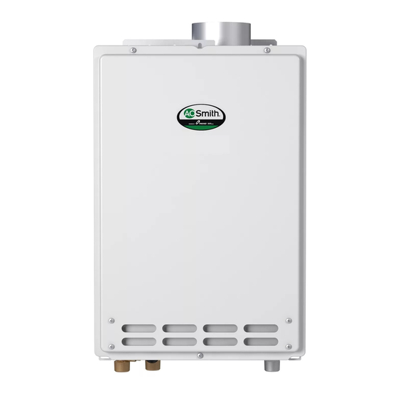
Page 4: Exterior View
CONFIDENTIAL 510 Indoor / 510 Outdoor Service Manual Ver. 1.00 2. Exterior view 510 Indoor Side view Front view Top view Bottom view... - Page 5 CONFIDENTIAL 510 Indoor / 510 Outdoor Service Manual Ver. 1.00 510 Outdoor Side view Front view Bottom view Top view...
-
Page 6: Interior View
CONFIDENTIAL 510 Indoor / 510 Outdoor Service Manual Ver. 1.00 3. Interior view 510 Indoor... - Page 7 CONFIDENTIAL 510 Indoor / 510 Outdoor Service Manual Ver. 1.00 510 Indoor...
-
Page 8: List Of Main Components In The Interior View
CONFIDENTIAL 510 Indoor / 510 Outdoor Service Manual Ver. 1.00 4. List of main components in the interior view Items# in Common parts Description components Part # for other models diagram 319143-151 (510 Indoor) Case assembly 319143-211 (510 Outdoor) 319143-046 (LP model) - Page 9 CONFIDENTIAL 510 Indoor / 510 Outdoor Service Manual Ver. 1.00 Items# in Common parts Description components Part # for other models diagram Outlet drain plug 319143-199 110, 310, 910 Air-fuel ratio rod (AFR rod) 319143-035 Flame rod 319143-035 Igniter rod...
-
Page 10: Schematic Diagram
The diagram below refers to both the 510 Indoor and 510 Outdoor. 1. When a hot water tap is opened, cold water enters the 510 Indoor or 510 Outdoor. 2. The water flow sensor detects this water flow and sends this information to computer. -
Page 11: Wiring Diagram
CONFIDENTIAL 510 Indoor / 510 Outdoor Service Manual Ver. 1.00 6. Wiring diagram The diagram below refers to both the 510 Indoor and 510 Outdoor. H2 B1 9007603005... -
Page 12: Wiring Diagram Checkpoints For Diagnosis
CONFIDENTIAL 510 Indoor / 510 Outdoor Service Manual Ver. 1.00 7. Wiring diagram check points for diagnosis The table below applies to both the 510 Indoor and 510 Outdoor. Check- Part and Description Color of wires Normal range point White – Black (A) - Page 13 CONFIDENTIAL 510 Indoor / 510 Outdoor Service Manual Ver. 1.00 Check- Part and Description Color of wires Normal range point 1 to 15 VDC (during operation) Gas proportional valve White - red 20 to 40 Ω Red - Black 4 to 5.5 VDC...
-
Page 14: Resistance Values Of The Temperature Thermistors
CONFIDENTIAL 510 Indoor / 510 Outdoor Service Manual Ver. 1.00 8. Resistance values of the temperature thermistors The 510 Indoor and 510 Outdoor use the same thermistors. Resistance values at different temperatures ºF Temperature ºC Resistance kΩ 23.76 19.08 15.43 12.56... -
Page 15: Operational Flow Chart
CONFIDENTIAL 510 Indoor / 510 Outdoor Service Manual Ver. 1.00 9. Operational flow chart The diagram below refers to both the 510 Indoor and 510 Outdoor. -
Page 16: Component Specifications
CONFIDENTIAL 510 Indoor / 510 Outdoor Service Manual Ver. 1.00 10. Component specifications 10-1. Burners……………………..………………………………………………………………………..………. 17 10-2. Gas manifold………….…………………………………………………………………………………..10-3. Fan motor………………………………………………………………………...…………………………… 19 10-4. Gas valve assembly………………..……………………….…………………………………………….. 20 10-5. Flame rod………………………………………………………….………………………………………….. 21 10-6. AFR rod…………………………………………………………………………………………………………. 22 10-7. Heat exchanger……………………………………………………………………………………………… 23 10-8. -
Page 17: Burners
Visual inspection: excessive dust deposit on the burner surface and/or Diagnostic unstable flame conditions during operation. Color/Number of wires The burner for the 510 Indoor and 510 Outdoor has the “46V” mark as shown below. Burner damper (#112 / 319143-156) The burner damper is not included in 319143-030. -
Page 18: Gas Manifold
CONFIDENTIAL 510 Indoor / 510 Outdoor Service Manual Ver. 1.00 10-2. Gas manifold Included 319143-046 (LP) Unit Part # AOS Part # Checkpoint in #102 319143-368 (NA) 1. The manifold distributes gas from the gas valves to the burners. The... -
Page 19: Fan Motor
CONFIDENTIAL 510 Indoor / 510 Outdoor Service Manual Ver. 1.00 10-3. Fan motor 319143-043 (510 Indoor) Unit Part # #103 AOS Part # Checkpoint 319143-217 (510 Outdoor) To provide combustion air into the combustion chamber and to exhaust flue Function gas. -
Page 20: Gas Valve Assembly
CONFIDENTIAL 510 Indoor / 510 Outdoor Service Manual Ver. 1.00 10-4. Gas valve assembly Included 319143-046 (LP) Unit Part # AOS Part # Checkpoint C,H1 in #102 319143-368 (NA) Opens and closes the gas pathways of the water heater (main and solenoid... -
Page 21: Flame Rod
CONFIDENTIAL 510 Indoor / 510 Outdoor Service Manual Ver. 1.00 10-5. Flame rod Unit Part # #108 AOS Part # 319143-035 Checkpoint To detect flames while the water heater is in operation. Function 1. Unable to detect flames when flames actually do occur. -
Page 22: Afr Rod
CONFIDENTIAL 510 Indoor / 510 Outdoor Service Manual Ver. 1.00 10-6. AFR rod Unit Part # #108 AOS Part # 319143-035 Checkpoint -Checks flame conditions during combustion. Function -When AFR rod detects unexpected flame conditions, the computer of the water heater makes adjustments in the fan motor speed to compensate. -
Page 23: Heat Exchanger
Color/Number of wires The heat exchanger of the 510 Indoor and 510 Outdoor has the “Pro” mark as shown below. 510 Indoor 510 Outdoor... -
Page 24: Flow Adjustment Valve
CONFIDENTIAL 510 Indoor / 510 Outdoor Service Manual Ver. 1.00 10-8. Flow adjustment valve Unit Part # #402 AOS Part # 319143-178 Checkpoint Controls water flow to properly control the output hot water temperature. Function 1. Water leakage from valve. -
Page 25: Flow Sensor
CONFIDENTIAL 510 Indoor / 510 Outdoor Service Manual Ver. 1.00 10-9. Flow sensor Unit Part # #402 AOS Part # 319143-178 Checkpoint Detects and measures water flow rate using a spinning impeller and Function magnetic pick-up. Unable to detect or measure any water flow rate. -
Page 26: Bypass Valve
CONFIDENTIAL 510 Indoor / 510 Outdoor Service Manual Ver. 1.00 10-10. Bypass valve Unit Part # #403 AOS Part # 319143-186 Checkpoint 1. Mixes hot water from the heat exchanger with cold water from the water inlet in order to modulate and control the water heater’s outlet water temperature. -
Page 27: Thermistors
CONFIDENTIAL 510 Indoor / 510 Outdoor Service Manual Ver. 1.00 10-11. Thermistors #407 (Inlet) 319143-085 (Inlet) E1 (Mixing) Unit Part # #408 (Mixing) AOS Part # 319143-190 (Mixing) Checkpoint E2 (Output) #411 (Output) 319143-096 (Output) E3 (Inlet) Measures cold/hot water temperatures in the water heater. -
Page 28: Hi-Limit Switch
"111" or "121" error code will display. Error codes when hi-limit The 510 Indoor / 510 Outdoor don't have the "141" error code that was used in switch fails our previous models. This error code is now replaced by the "111" and the "121"... -
Page 29: Overheat Cutoff Fuse
CONFIDENTIAL 510 Indoor / 510 Outdoor Service Manual Ver. 1.00 10-13. Overheat cut off fuse Unit Part # #413 AOS Part # 319143-149 Checkpoint -The overheat cutoff fuse contains solder with a melting point of 430˚F (221˚C). -Detects excessive temperatures within the water heater, especially around... -
Page 30: Freeze Protection Heaters
CONFIDENTIAL 510 Indoor / 510 Outdoor Service Manual Ver. 1.00 10-14. Freeze protection heaters #414 319143-200 Unit Part # AOS Part # Checkpoint #415 319143-078 Prevents the heat exchanger, water valves, and water pipes within the water Function heater from freezing. The heaters are but one of the freeze protection devices in the water heater. -
Page 31: Computer Board
CONFIDENTIAL 510 Indoor / 510 Outdoor Service Manual Ver. 1.00 10-15. Computer board Unit Part # #701 AOS Part # 319143-179 Checkpoint Controls the functions of most of the parts in the water heater. Function Malfunctioning computer Failure events -A component(s) may not operate within the water heater. In most cases... -
Page 32: Transformer
CONFIDENTIAL 510 Indoor / 510 Outdoor Service Manual Ver. 1.00 10-16. Transformer Unit Part # #702 AOS Part # 319143-182 Checkpoint A1,A2 -To transform input voltage from 120 to 100 VAC. -Every electrical component of the water heater is designed to only work... -
Page 33: Igniter
CONFIDENTIAL 510 Indoor / 510 Outdoor Service Manual Ver. 1.00 10-17. Igniter Unit Part # #711 AOS Part # 319143-052 Checkpoint -To ignite the gas/air mixtures when the water heater is ready to burn gas on Function its burner surface. -
Page 34: Freeze Protection Thermostat
CONFIDENTIAL 510 Indoor / 510 Outdoor Service Manual Ver. 1.00 10-18. Freeze protection thermostat #713 319143-185 (510 Indoor) Unit Part # AOS Part # Checkpoint #710 319143-210 (510 Outdoor) Temperature detecting device which prevents the pipes within the water heater from freezing. When this device detects temperatures below 36.5˚F Function (2.5˚C) inside the water r heater, power is supplied to the electric heaters to... -
Page 35: Surge Box
CONFIDENTIAL 510 Indoor / 510 Outdoor Service Manual Ver. 1.00 10-19. Surge box Unit Part # #703 AOS Part # 319143-168 Checkpoint A2,A3 Protects the unit from high voltage and/or high electric current caused by lightning. Function There are 2 types of surge absorbers in the water heater. Surge absorber A is activated by voltage higher than 220V, the other one is activated by voltage higher than 680V. -
Page 36: Fault Analysis & Specifications
CONFIDENTIAL 510 Indoor / 510 Outdoor Service Manual Ver. 1.00 11. Fault Analysis & Specifications Remarks: 1. Proper range of values of voltage & resistance shown below. 2. Please refer to the wiring diagram for checkpoint positions. Remove power to the water heater when checking for continuity, disconnections, resistance values, etc. - Page 37 CONFIDENTIAL 510 Indoor / 510 Outdoor Service Manual Ver. 1.00 Natural of Fault Diagnosis Checkpoint 5 Check that the filter on the cold water inlet is clean. The hot water is not 6 Check whether or not the unit is frozen.
- Page 38 CONFIDENTIAL 510 Indoor / 510 Outdoor Service Manual Ver. 1.00 Natural Checkpoint Diagnosis Fault 4 Fault of PCB in the water heater Fluctuation [1] No voltage to gas solenoid valve (SV of hot water Normal: 78 to 100 VDC between COM (blue) & #9 (green)
- Page 39 CONFIDENTIAL 510 Indoor / 510 Outdoor Service Manual Ver. 1.00 Error Code Diagnosis Checkpoint 8 Check if there is grease and dirt in burner and fan motor, when the water heater has been installed in restaurant. 9 Check the manifold pressure in the water heater.
- Page 40 CONFIDENTIAL 510 Indoor / 510 Outdoor Service Manual Ver. 1.00 Error Code Diagnosis Checkpoint 5 Disconnected/damaged O.H.C.F. (Refer to section 10-13) V isual inspection: connection/breakage of wires. Normal: 1 Ω or less between blue & blue 6 Disconnected/damaged hi-limit switch. (Refer to section 10-12) V isual inspection: connection/breakage of wires.
- Page 41 CONFIDENTIAL 510 Indoor / 510 Outdoor Service Manual Ver. 1.00 Error Code Diagnosis Checkpoint 4 Check for soot on the flame rod [1] Clean the flame rod [2] PCB fault During operation: more than 1 μA through the flame rod wire (orange) 5 Disconnected/damaged O.H.C.F.
- Page 42 CONFIDENTIAL 510 Indoor / 510 Outdoor Service Manual Ver. 1.00 Error Code Malfunction description Cancellation method Disconnected AFR rod Turn off the power or water supply Diagnosis Checkpoint 1 AFR rod fault (Refer to section 10-6) V isual inspection: connection/breakage of wires, soot on it.
- Page 43 CONFIDENTIAL 510 Indoor / 510 Outdoor Service Manual Ver. 1.00 Error Code Malfunction description Cancellation method Fan motor fault Turn off the power or water supply Diagnosis Checkpoint 1 PCB and fan motor fault (Refer to section 10-3 & 10-15)
- Page 44 CONFIDENTIAL 510 Indoor / 510 Outdoor Service Manual Ver. 1.00 Error Code Malfunction description Cancellation method 1 PCB fault [1] Fault of preparation for the mixing thermistor operation. Turn off the power or water supply [2] Fault of driving circuit for Gas Proportional...
- Page 45 CONFIDENTIAL 510 Indoor / 510 Outdoor Service Manual Ver. 1.00 Error Code Malfunction description Cancellation method Restoring proper cable connections among all the water heaters. When the Miscommunication between Parent and Child computer detects proper connections units for Easy Link systems.
-
Page 46: Controls And Settings
CONFIDENTIAL 510 Indoor / 510 Outdoor Service Manual Ver. 1.00 12. Controls and settings 12-1. Diagnosis using the 9007603005…………………………………………………………………….……………….. 12-2. The error-code button: Verifying functionality of computer board, Displaying error code history, and Clearing error code history memory…......………......12-3. Clearing the “101” and “991” error code……………………………………………………………………………... -
Page 47: Diagnosis Using The 9007603005
CONFIDENTIAL 510 Indoor / 510 Outdoor Service Manual Ver. 1.00 12-1. Diagnosis using the 9007603005 < Individual unit> 1. Press the "HOT" button and the "COLD" button simultaneously for at least 5 seconds to enter “Diagnostic mode”. “HOT” “TIME” 2. Scroll up or down to the needed information (mode #) of the 510 “COLD”... - Page 48 2. "0" will be displayed on the 9007603005. (See Fig. 1) 3. Scroll to the desired 510 Indoor or 510 Outdoor unit # in the easy-link system by pressing the "HOT" or the "COLD" buttons to scroll up or down. (Fig. 2 shows that unit #2 is being selecting) NOTE: The definition of the unit #’s:...
- Page 49 CONFIDENTIAL 510 Indoor / 510 Outdoor Service Manual Ver. 1.00 Description of mode numbers in “Diagnostics Mode” Mode # Whole multi-unit system information (#0) Unit information (#1 to #4) Total system flow 0 to 999 (×0.1 GPM) Total operation time...
-
Page 50: The Error-Code Button: Verifying Functionality Of Computer Board, Displaying Error Code History, And Clearing Error Code History Memory
1. Briefly press the “Error-call button” (do not hold down the button). 2. If the 510 Indoor or 510 Outdoor has had prior error codes, the 7-seg LED will display the most recent error code first. Pressing the button again will display the 2... -
Page 51: Clearing The "101" And "991" Error Code
CONFIDENTIAL 510 Indoor / 510 Outdoor Service Manual Ver. 1.00 12-3. Clearing the “101” and “991” error code The “101” and “991” error codes signify imperfect (abnormal) combustion, caused by insufficient intake air and/or obstructions in the exhaust. A. If the “101” and “991” error code occurs, please check the following: 1. -
Page 52: Afr Rod Function
CONFIDENTIAL 510 Indoor / 510 Outdoor Service Manual Ver. 1.00 12-4. AFR rod function <Function> The AFR rod checks flame conditions during combustion. When the AFR rod detects unexpected flame conditions, the computer board of the 510 adjusts the fan motor speed to ensure that air and fuel are always at a proper mixture ratio, minimizing emissions. -
Page 53: Dipswitch Settings
12-5. Dipswitch settings Upper bank of dipswitches The 510 Indoor shares the computer board with the 510 Outdoor. There are two banks of dipswitches (upper and lower bank) on the computer board. The upper bank has certain special functions as shown on the following table and generally should not need adjustment. - Page 54 CONFIDENTIAL 510 Indoor / 510 Outdoor Service Manual Ver. 1.00 The function of the lower bank of dipswitches Functions ON position OFF position Parent/Child setting for Easy-Link systems Parent Child (Default) Model type (Default) Disable 510 Indoor (Default) Disable 510 Outdoor...
-
Page 55: Assigning Unit Numbers In The Easy-Link System
3. Press and hold the "Increase" button on each unit in the new order of your choosing. The new unit numbers will be assigned in this order. Each 510 Indoor or 510 Outdoor in an Easy-link system is assigned a random unit #, except for the Parent unit, which is always assigned as unit #1. -
Page 56: A) On/Off Conditions: Overview
510 Indoor / 510 Outdoor Service Manual Ver. 1.00 12-7. (A) ON/OFF conditions: Overview The following table shows the ON/OFF conditions of the 510 Indoor or 510 Outdoor. ON/OFF Conditions The BTU requirement is more than 14,880 BTU/h Conditions needed to turn ON. -
Page 57: B) On/Off Conditions: Btu Requirements
510 Indoor / 510 Outdoor Service Manual Ver. 1.00 12-7.(B) ON/OFF conditions: BTU requirements A. Calculating the ON/OFF conditions of the 510 Indoor or 510 Outdoor Condition needed to turn the T-H2-DV or T-H2-OS ON – T ) × GPM × 500 > 14,880 Condition needed to turn the T-H2-DV or T-H2-OS OFF –... -
Page 58: A) Pump Control On/Off Conditions (Only For Single And Easy-Link System)
Ver. 1.00 12-8. (A) Pump control ON/OFF Conditions (Only for single and Easy-link system) To run circulation pumps efficiently and effectively, the 510 Indoor / 510 Outdoor offers mode of pump control. The following table shows the pump control ON/OFF conditions. -
Page 59: B) Pump Control On/Off Conditions: Btu Requirements
CONFIDENTIAL 510 Indoor / 510 Outdoor Service Manual Ver. 1.00 12-8.(B) Pump control ON/OFF conditions: BTU requirements A. Calculating the ON/OFF conditions of the pump Condition needed to turn the pump ON – T ) × GPM × 500 > 18,600... -
Page 60: Multi-Unit System On/Off Conditions
Ver. 1.00 12-9. Multi-unit system ON/OFF conditions In an Easy-Link system, the amount of 510 Indoor or 510 Outdoor called on to activate depends on the FLOW RATE and the SET TEMPERATURE. 1. Condition required to activate an additional 510 Indoor or 510 Outdoor: Flow rate required to activate additional 510 Indoor or 510 Outdoor = A ×... -
Page 61: High-Altitude Region Support Functions (Fm+, Fm++ And Fm+++)
CONFIDENTIAL 510 Indoor / 510 Outdoor Service Manual Ver. 1.00 12-10. High-Altitude Region Support Functions (FM+, FM++ and FM+++) Using these functions The high-altitude region support functions have four operation levels, with the appropriate level being set up by the installer until the abnormal sound problem is solved. -
Page 62: Relay Selection For The Pump Control Connection
12-11. Relay selection for the pump control connection The maximum current capacity of 510 Indoor or 510 Outdoor pump control connection is 1 amp. Before using any relay with the pump control, please check the specifications of that particular relay to ensure that the current value through the coil will not exceed 1 amp. -
Page 63: Adjusting Manifold Gas Pressure
4. Run water through the 510 Indoor or 510 Outdoor to activate its operation. If presence of a gas leak is detected, immediately shut off the 510 Indoor or 510 Outdoor and inspect the tube/manifold connection;... - Page 64 CONFIDENTIAL 510 Indoor / 510 Outdoor Service Manual Ver. 1.00 desired value. 6. After gas pressure has been set, deactivate the 510 Indoor or 510 Outdoor, remove the manometer tube, and replace the port screw. Figure 1 Manifold port Figure 2...
-
Page 65: Manually Adjusting The Fan Motor Speed
Adjusting maximum fan motor speed 1. While 510 Indoor or 510 Outdoor is in operation, set dipswitch No.3 to the “ON” position. (Figure 1) 2. On the temperature remote controller, display mode #3 (fan motor speed) by entering the “Diagnostics mode”... -
Page 66: Freeze Protection System
The three heating blocks focus on protecting the inlet and outlet piping inside the 510 Indoor or 510 Outdoor, as well as the front drum pipe. The conditions to activate either feature are different from each other. However, the two features are not mutually exclusive, because they focus on different areas of the 510 Indoor or 510 Outdoor. - Page 67 37°F and below 510 Outdoor installation After 25 minutes have elapsed since the 510 Indoor or 510 Outdoor’s previous firing operation, the computer will continually check the temperatures of the inlet and output thermistors. automatic firing system will not activate at all unless these 25 minutes have elapsed.
- Page 68 The blocks will only activate based on what the freeze protection thermostat senses. The thermostat is located on the fan motor, close in vicinity to the inlet and outlet pipes within the 510 Indoor or 510 Outdoor. Electrical power is required for this feature to operate.
-
Page 69: Draining The Unit And Cleaning The Inlet Water Filter
12-15. Draining and cleaning the inlet water filter Close the manual gas shut off valve. 2. Turn off power to the 510 Indoor or 510 Outdoor, wait a few seconds. And then turn on again. Wait 30 seconds for water valves starts to completely open. Then turn off power to the 510 Indoor or 510 Outdoor, yet again. -
Page 70: Components Diagrams
CONFIDENTIAL 510 Indoor / 510 Outdoor Service Manual Ver. 1.00 13. Components diagrams Case assembly 510 Indoor 510 Outdoor... -
Page 71: Burner Assembly
CONFIDENTIAL 510 Indoor / 510 Outdoor Service Manual Ver. 1.00 Burner assembly 510 Indoor/Outdoor Burner assembly Power control section 510 Indoor Manifold Fan motor section for IN models assembly 510 Outdoor Fan motor section for OS models... - Page 72 CONFIDENTIAL 510 Indoor / 510 Outdoor Service Manual Ver. 1.00 Computer 510 Indoor/Outdoor board assembly Water way assembly 510 Indoor/Outdoor Bypass section Exhaust section (OS model) Water outlet section Water inlet section...
-
Page 73: Parts List
CONFIDENTIAL 510 Indoor / 510 Outdoor Service Manual Ver. 1.00 14. Parts list Item # Part # Description Common parts for other models 319143-151 Case assembly (IN) 319143-211 Case assembly (Out) 319143-174 Front cover (IN) 319143-175 Front cover (Out) 319143-150 Air blockage plate... - Page 74 CONFIDENTIAL 510 Indoor / 510 Outdoor Service Manual Ver. 1.00 Item # Part # Description Common parts for other models 319143-043 Fan motor (IN) 520, 310, 910, 710 319143-217 Fan motor (Out) 319143-032 Burner holder gasket 520, 310, 910 319143-031 Burner gasket...
- Page 75 CONFIDENTIAL 510 Indoor / 510 Outdoor Service Manual Ver. 1.00 Item # Part # Description Common parts for other models 319143-197 Inlet drain plug 110, 310 319143-198 Inlet water filter 110, 310 319143-085 Inlet thermistor 520, 910, 710 319143-190 Mixing thermistor...
- Page 76 CONFIDENTIAL 510 Indoor / 510 Outdoor Service Manual Ver. 1.00 Item # Part # Description Common parts for other models 319143-141 AC 120V Power ON-OFF switch 520, 110, 310 319143-181 Switch wire 319143-188 Gas valve wire 110, 310 319143-189 Flame rod wire...
-
Page 77: Revisions
CONFIDENTIAL 510 Indoor / 510 Outdoor Service Manual Ver. 1.00 15. Revisions Version Description of changes Date 1.00 First edition 11/01/10...