Table of Contents
Advertisement
Quick Links
Service Manual
The components designated by a symbol (
significance to product safety. Should any component designated by a symbol need to be replaced, use only the part designated
in the parts List. Do not deviate from the resistance, wattage, and voltage ratings shown.
NOTE:
1.
Substitute parts may be supplied as the service parts.
2.
N.S.P.: Not available as service parts.
Design and specifications are subject to change without notice.
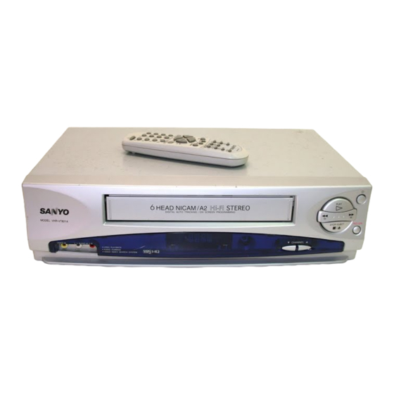
Video Cassette
Recorder
PRODUCT SAFETY NOTICE
) in this schematic diagram designates components whose value are of special
FILE NO.
VHR-VT821A
(Product Code: 1 682 333 57)
(Australia)
VHR-VT821A / NZ
(Product Code: 1 682 333 58)
(New Zealand)
REFERENCE No. SM2200001
Advertisement
Table of Contents

Related Manuals for Sanyo VHR-VT821A


Summary of Contents for Sanyo VHR-VT821A
- Page 1 Video Cassette VHR-VT821A Recorder (Product Code: 1 682 333 57) (Australia) VHR-VT821A / NZ (Product Code: 1 682 333 58) (New Zealand) PRODUCT SAFETY NOTICE The components designated by a symbol ( ) in this schematic diagram designates components whose value are of special significance to product safety.
-
Page 2: Servicing Notices On Checking
SERVICING NOTICES ON CHECKING 1. KEEP THE NOTICES 3. PUT PARTS AND WIRES IN THE ORIGINAL POSITION AFTER As for the places which need special attentions, ASSEMBLING OR WIRING they are indicated with the labels or seals on the cabinet, chassis and parts. Make sure to keep the There are parts which use the insulation indications and notices in the operation manual. -
Page 3: Table Of Contents
TABLE OF CONTENTS SERVICING NOTICES ON CHECKING ..................HOW TO ORDER PARTS ......................TAPE REMOVAL METHOD AT NO POWER SUPPLY ............TABLE OF CONTENTS ......................GENERAL SPECIFICATIONS ....................DISASSEMBLY INSTRUCTIONS 1. REMOVAL OF MECHANICAL PARTS AND P. C. BOARDS ..........2. -
Page 4: General Specifications
GENERAL SPECIFICATIONS System VHS Player / Recorder System Video System Hi-Fi STEREO NTSC PB(PAL60Hz) Deck DECK OVD-7 Loading System Front Motor Heads Video Head 4Head FM Audio Head 2Head Audio /Control Mono/Yes Erase(Full Track Erase) Tape SP/LP Speed NTSC Play SP/LP NTSC Fast Forward / Rewind Time (Approx.) - Page 5 GENERAL SPECIFICATIONS On Screen Menu Display Menu Type Character Timer Rec Set VCR Extension Auto Repeat On/Off Scene Repeat Audio Dubbing VCR Set-Up NICAM Auto/Off Audio Mix On/Off Color System Sharpness BBE On/Off CH Set-Up CH Tuning Auto Tuning CH Mapping Guide CH Set Pin Code Registration System Set-Up...
- Page 6 GENERAL SPECIFICATIONS G-12 Remote Unit RC-ED Control Glow in Dark Remocon Power Source Voltage(D.C) UM size x pcs UM-4 x 2 pcs Total Keys 32 Keys Keys Power 0 / AV CH / Tracking Up CH / Tracking Down Input Select Play Play / Up Play / Up / Slow...
- Page 7 GENERAL SPECIFICATIONS G-14 Accessories Owner's Manual Language English w/Guarantee Card Remote Control Unit Dew Cation Sheet Battery UM size x pcs UM-4 x 2 pcs Tape Rewinder Safety Tip Toll Free Insert Sheet Quick Set-Up Sheet Information Sheet 75 Ohm Coaxial Cable type Single shield U/V Mixer...
-
Page 8: Disassembly Instructions
DISASSEMBLY INSTRUCTIONS 1-3: DECK CHASSIS (Refer to Fig. 1-3) 1. REMOVAL OF MECHANICAL PARTS Remove the 3 screws 1. AND P.C. BOARDS Disconnect the 6P ribbon wire (CD1002) from Audio 1-1: TOP CABINET, FRONT CABINET AND head (H5001). OPERATION PCB (Refer to Fig. 1-1) Remove the Deck Chassis in the direction of arrow. -
Page 9: Removal Of Deck Parts
DISASSEMBLY INSTRUCTIONS 2. REMOVAL OF DECK PARTS NOTE In case of the Locker R installation, check if the two 2-1: TOP BRACKET (Refer to Fig. 2-1) positions of Fig.2-3-B are correctly locked. Extend the 2 supports 1. When you install the Cassette Side R, be sure to move Slide the 2 supports 2 and remove the Top Bracket. - Page 10 DISASSEMBLY INSTRUCTIONS 2-6: LOADING MOTOR/WORM (Refer to Fig. 2-6-A) Tension Arm Ass'y Remove the screw 1. Remove the Loading Motor. Remove the Worm. Fig. 2-7-A Loading Motor Worm Tension Connect Tension Band Main Chassis Tension Spring Tension Arm Ass'y Tension Holder •...
- Page 11 DISASSEMBLY INSTRUCTIONS 2-8: T BRAKE ARM/T BRAKE BAND (Refer to Fig. 2-8-A) Remove the T Brake Spring. Idler Gear Turn the T Brake Arm clockwise and bend the hook Idler Arm Ass'y section to remove it. Unlock the 2 supports 1 and remove the T Brake S Reel Band.
- Page 12 DISASSEMBLY INSTRUCTIONS 2-10: CASSETTE OPENER/PINCH ROLLER BLOCK/ P5 ARM ASS'Y (Refer to Fig. 2-10-A) Unlock the support 1 and remove the Cassette Opener. Remove the Pinch Roller Block and P5 Arm Ass'y. Cassette Opener Spring Position Fig. 2-11-B 2-12: FE HEAD (RECORDER ONLY) (Refer to Fig. 2-12) Pinch Roller Block Remove the screw 1.
- Page 13 DISASSEMBLY INSTRUCTIONS 2-14: CAPSTAN DD UNIT (Refer to Fig. 2-14-A) 2-15: MAIN CAM/PINCH ROLLER CAM/JOINT GEAR (Refer to Fig. 2-15-A) Remove the Capstan Belt. Remove the 3 screws 1. Remove the E-Ring 1, then remove the Main Cam. Remove the E-Ring 2, then remove the Pinch Roller Remove the Capstan DD Unit.
- Page 14 DISASSEMBLY INSTRUCTIONS NOTE 2-18: CASSETTE GUIDE POST/INCLINED BASE S/T UNIT/P4 CAP (Refer to Fig. 2-18-A) 1. When you install the Loading Arm S Unit, Loading Arm T Unit and Main Loading Gear, align each marker. Remove the P4 Cap. Unlock the support 1 and remove the Cassette Guide (Refer to Fig.
-
Page 15: Removal And Installation Of Flat Package Ic
DISASSEMBLY INSTRUCTIONS REMOVAL AND INSTALLATION OF When IC starts moving back and forth easily after desoldering completely, pickup the corner of the IC using FLAT PACKAGE IC a tweezers and remove the IC by moving with the IC desoldering machine. (Refer to Fig. 3-3.) REMOVAL NOTE Put the Masking Tape (cotton tape) around the Flat... - Page 16 DISASSEMBLY INSTRUCTIONS INSTALLATION When bridge-soldering between terminals and/or the soldering amount are not enough, resolder using a Thin- Take care of the polarity of new IC and then install the tip Soldering Iron. (Refer to Fig. 3-8.) new IC fitting on the printed circuit pattern. Then solder each lead on the diagonal positions of IC temporarily.
-
Page 17: Key To Abbreviations
KEY TO ABBREVIATIONS Audio/Control H.SW Head Switch Automatic Color Control Hertz Audio Erase Integrated Circuit Automatic Frequency Control Intermediate Frequency Automatic Fine Tuning Indicator AFT DET Automatic Fine Tuning Detect Inverter Automatic Gain Control Killer Amplifier Left Antenna Light Emitting Diode A.PB Audio Playback LIMIT AMP... - Page 18 KEY TO ABBREVIATIONS SYNC Synchronization SYNC SEP Sync Separator, Separation Transistor TRAC Tracking TRICK PB Trick Playback Test Point UNREG Unregulated Volt Voltage Controlled Oscillator Video Intermediate Frequency Vertical Pulse, Voltage Display V.PB Video Playback Variable Resistor V.REC Video Recording Visual Search Fast Forward Visual Search Rewind Voltage Super Source...
-
Page 19: Error Code List
ERROR CODE LIST If the error indications are appeared on the FIP, check the abnormal points by using the table below. Indications Error contents Reel mecha error Error : 01 Error : 02 Cylinder mecha error Error : 03 Mecha state error Error : 04 Capstan mecha error SERVICE MODE LIST... -
Page 20: Preventive Checks And Service Intervals
PREVENTIVE CHECKS AND SERVICE INTERVALS The following standard table depends on environmental conditions and usage. Parts replacing time does not mean the life span for individual parts. Also, long term storage or misuse may cause transformation and aging of rubber parts. The following list means standard hours, so the checking hours depends on the conditions. - Page 21 PREVENTIVE CHECKS AND SERVICE INTERVALS CLEANING NOTE 2. TAPE RUNNING SYSTEM After cleaning the heads with isopropyl alcohol, do not When cleaning the tape transport system, use the run a tape until the heads dry completely. If the heads gauze moistened with isopropyl alcohol. are not completely dry and alcohol gets on the tape, 3.
-
Page 22: When Replacing Eeprom (Memory) Ic
WHEN REPLACING EEPROM (MEMORY) IC If a service repair is undertaken where it has been required to change the MEMORY IC, the following steps should be taken to ensure correct data settings while making reference to TABLE 1. Table 1 Turn on the POWER. -
Page 23: Servicing Fixtures And Tools
SERVICING FIXTURES AND TOOLS (For 2 head 1 speed model, (For 2 head 2 speed model) JG002B Adapter JG005 Post Adjustment 4 head model) VHS Alignment Tape JG002E Dial Torque Gauge Screwdriver VHS Alignment Tape JG001C (VP S-LI6 ) (10~90gf•cm) Part No. -
Page 24: Mechanical Adjustments
MECHANICAL ADJUSTMENTS 1. CONFIRMATION AND ADJUSTMENT 1-2: CONFIRMATION AND ADJUSTMENT OF TENSION POST POSITION Read the following NOTES before starting work. Set to the PLAY mode. • Place an object which weighs between 450g~500g on Adjust the adjusting section for the Tension Arm the Cassette Tape to keep it steady when you want to position so that the Tension Arm top is within the make the tape run without the Cassette Holder. - Page 25 MECHANICAL ADJUSTMENTS 1-4: CONFIRMATION OF VSR TORQUE NOTE Install the Torque Gauge (JG002F) and Adapter (JG002B) If the torque is out of the range, replace the following on the S Reel. Set to the Picture Search (Rewind) mode. parts. (Refer to Fig.1-4-B) Replacement Part Check item Then, confirm that it indicates 120~180gf•cm.
- Page 26 MECHANICAL ADJUSTMENTS 2-2: CONFIRMATION AND ADJUSTMENT OF AUDIO/ 2-3: TAPE RUNNING ADJUSTMENT CONTROL HEAD (X VALUE ADJUSTMENT) When the Tape Running Mechanism does not work well, Confirm and adjust the height of the Reel Disk. adjust the following items. (Refer to item 1-1) Confirm and adjust the position of the Tension Post.
- Page 27 MECHANICAL ADJUSTMENTS 3. MECHANISM ADJUSTMENT PARTS LOCATION GUIDE 1. Tension Connect P4 Post 2. Tension Arm T Brake Spring 3. Guide Roller T Reel 4. Audio/Control Head S Reel 5. X value adjustment driver hole Adjusting section for the Tension Arm position...
-
Page 28: Electrical Adjustments
ELECTRICAL ADJUSTMENTS Read and perform this adjustment when repairing the 1-2: PB-Y LEVEL circuits or replacing electrical parts or PCB assemblies. CONDITIONS 1. BASIC ADJUSTMENT MODE-PLAYBACK Input Signal-Alignment Tape (JG001F) CAUTION INSTRUCTIONS When you exchange IC and Transistor for a heat sink, apply the silicon grease (YG6260M) on the contact Connect the oscilloscope to pin 5 of CP4503 through 75 section of the heat sink. - Page 29 ELECTRICAL ADJUSTMENTS 1-5: PB AUDIO LEVEL CONDITIONS MODE-Self (RECORD and PLAYBACK) Audio Signal: 1KHz, 500mVrms Input Signal- Video Signal: PAL Color Bar Input Select-AV INSTRUCTIONS Connect the color bar generator to pin 9 of CP4503. Connect the audio generator to pin 7 of CP4503 and pin 11 of CP4503.
- Page 30 ELECTRICAL ADJUSTMENTS 2. ELECTRICAL ADJUSTMENT PARTS LOCATION GUIDE (WIRING CONNECTION) AUDIO PCB J4503 CP4501 TP4001 AC IN CP4002 TP4002 S501 S502 CP4503 A/C HEAD TP1001 T501 J4507 J4506 J4505 CP651 SYSCON PCB OPERATION PCB CP601...
-
Page 31: Y/C/Audio/Head Amp
Y/C/AUDIO/HEAD AMP BLOCK DIAGRAM CP4001 X4001 4.433619MHz HF1 (R) HF_COM HF2 (L) SP-CH1 (R) X TAL VCO/OSD CR DET 2FSC SP_COM 2MLPF SP-CH2 (L) CTL TRAP 6db AMP FH HPF 6db AMP EP/LP-CH1 (R) EP/LP_COM CLPF C SQUELCH DELAY CLPF CLEAR EP/LP-CH2 (L) TRAP... -
Page 32: Y/C/Audio/Head Amp
SYSTEM CONTROL/SERVO/TIMER BLOCK DIAGRAM P. CON + 5V REEL SENS Q1003 SYSCON/SOFTWARE/SERVO IC IC1001 OEC7070B REEL SENS Q1001 REEL-S REEL-T REMOCON REMOCON XC IN X1002 KEY-A OPERATION KEY-A IC1003 32.768KHz XC OUT PST3231NR CH. UP_SW KEY-B SYSTEM 43 RESET EEP ROM IC IIC-SDA RESET IC IC1099... - Page 33 TUNER/Hi-Fi/21PIN/OSD/VPS/NICAM BLOCK DIAGRAM NICAM IC IC6601 TDA9874H X6601 24.576MHz VIDEO_IN EE/VV_V_OUT Y/C/AUDIO/ HEAD AMP 2FSC TU_V_OUT Q4802 BUFFER J4503 TU6001 OSD IC IC4801 OEC3031A CG_DATA CG_CLK CG_CS SYSCON/SERVO/ IIC_CLK TIMER IIC_DATA HI-FI/AUDIO/CANAL SW IC IC5501 TDA9605H HF_COM Y/C/AUDIO/ HEAD AMP NORMAL_A_IN NORMAL_A_OUT FRONT_V_IN...
-
Page 34: Power Block Diagram
OPERATION BLOCK DIAGRAM V651 LTG-Y2K22M-J 13 12 11 10 9 15 14 Q665 POWER GRID5 5G SW Q664 CH UP CH. UP_SW SEG10 SW SEG10 Q663 SEG9 SEG9 SW KEY-A SYSCON/SERVO/ CH-DOWN Q662 TIMER 4G SW GRID4 STOP/EJECT REMOCON OS651 Q661 SEG8 SW SEG8... - Page 36 PRINTED CIRCUIT BOARDS SYSCON (INSERTED PARTS) SOLDER SIDE V651 J4506 J4505 J4507 W072 IC1099 C4088 R678 X1001 W112 W066 W111 R1033 C6608 R1032 W872 R1024 R1027 L4804 W832 W065 W873 R1036 C1011 W128 W127 W874 Q1001 W087 W863 W851 W826 R1005 W864 L6601...
-
Page 37: Operation
AUDIO (INSERTED PARTS) SOLDER SIDE CP4501 W824 L501 SW651_1 SW652_1 Q511 CP651 R524 R525 X1001 W005 W032 R1086 W031 R1011 W001 W030 C1013 R1006 W010 D1006 C513 W045 R520_1 W009 C521 D512 D515 D510 R517 D509 W008 OPERATION D501 W007 SOLDER SIDE D1004 R1031... - Page 38 PRINTED CIRCUIT BOARDS SYSCON (CHIP MOUNTED PARTS) SOLDER SIDE C4037 R4011 C4011 R4012 R4005 C4007 R4028 R4017 C4019 Q4005 C4072 C512 R516 C505 R501 R513 R1008 C510 Q1010 R5502 C1025 Q1009 Q1008 R1048 R1041 R1038 IC1003_1 R1026 R1025 R1043 Q659 Q660 Q664 Q663...
- Page 39 AUDIO (CHIP MOUNTED PARTS) SOLDER SIDE VEA966A C4504 C4502 R4504 C4501 C4054 R4505 R4508 R5507 C5520 C4532 C4530 C4529 R5508 R5510 R4802 Q4003 R1009 D6601 C4802 R4807 C4814 IC4801...
- Page 40 Y/C/AUDIO/HEAD AMP SCHEMATIC DIAGRAM (SYSCON PCB) FROM/TO SYSCON/SERVO/TIMER V.H_SW PICTURE_CTL NA_REC-H DUMMY_V.SYNC SYNC A_MUTE/TRICK-H IIC_DATA IIC_CLK ENV.DET CTL+ CTL- V.REC_ST-H FROM/TO 21PIN/OSD/VPS V.ENV TP4002 C4068 2FSC C4019 VIDEO_IN 0.022 B C4071 Y/C/AUDIO/CCD EE/VV_V_OUT 0.001 B H.SW /HEAD AMP IC FRONT_V_IN 0.01 F TP4001 C4013...
- Page 41 SYSTEM CONTROL/SERVO/TIMER SCHEMATIC DIAGRAM (SYSCON PCB) FROM/TO POWER (S/S) (MOTOR) AT+5.8V P.CON+5V AT+5.8V_A POWER_ON-H TO OSD/VPS POWER_FAIL CAP_VCO CG_CS AT+12.6V CG_CLK CG_DATA R1028 W814 27K 1/4W C1029 FROM/TO Y/C/AUDIO/HEAD AMP 6.3V V.H_SW NC NC PICTURE_CTL NC NC NA_REC-H C1002 R1049 DUMMY_V.SYNC FROM/TO DECK 18P CH...
- Page 42 POWER SCHEMATIC DIAGRAM (SYSCON PCB) TO TUNER/HI-FI R514 D501 +32V 1SS244 470 1/4W D507 VCC+12V_A 1N4005-EIC P.CON+5V D503 1N4005-EIC 240V_50Hz D505 CD501_1 06469801 L503 1N4005-EIC BLUE S502 FH501 FH502 0R3A433F20 EYF-52BC EYF-52BC D504 BROWN S501 TRANSFORMER 1N4005-EIC SWITCHING W866 T501 TO OSD/VPS F501 8122017...
- Page 43 OPERATION SCHEMATIC DIAGRAM (SYSCON PCB) V651 LTG-Y2K22AM-J 1G SW Q651 2SA1037AK 5.06 1.97 SEG1 SW Q652 KRC103SRTK OS651 PIC-37043LO R659 SEG2 SW Vout Q653 3.26 KRC103SRTK R661 SEG3 SW 5G SW Q654 Q665 3.94 2SA1037AK KRC103SRTK R662 1.05 5.06 2G SW SEG10 SW FROM/TO SYSCON/SERVO Q664...
-
Page 44: Tuner/Hi-Fi
TUNER/Hi-Fi SCHEMATIC DIAGRAM (SYSCON PCB) TU6001 TCMB0601PD13D AT+5V W843 RF_CONV.A_OUT A.IN L6001 P.CON+5V 22uH 0305 C6007 RF_CONV.V V.IN R5504 R5509 6.3V +32V TU(MD) L5501 C5524 active s-by Vref Iref Supply 10.5 NORMAL_A_OUT passive s-by 100uH playback C5529 level amplification detector decoder 0305 NORMAL_A_IN... - Page 45 OSD/VPS SCHEMATIC DIAGRAM (SYSCON PCB) REAR_A/V_JACK(STEREO) J4503 KM04003M CP4501 CP4503 B2013H02-11P B2013H02-11P R4503 AUDIO_OUT-R AUDIO_OUT-R A_OUT_R R4504 A_OUT_L AUDIO_OUT-L AUDIO_OUT-L V_OUT VIDEO_OUT VIDEO_OUT W829 AUDIO_OUT-R R4505 AUDIO_IN-L A_IN_R AUDIO_IN-L AUDIO_IN-L 2.7K A_IN_L VIDEO_IN V_IN VIDEO_IN VIDEO_IN W835 AUDIO_OUT-L R4508 AUDIO_IN-R AUDIO_IN-R AUDIO_IN-R 2.7K...
-
Page 46: Nicam
NICAM SCHEMATIC DIAGRAM (SYSCON PCB) FROM/TO SYSCON/SERVO/TIMER W863 IIC_DATA W864 IIC_CLK C6616 47P SL FROM POWER P.CON+5V FROM/TO TUNER/HI-FI W832 SIF/TU_A_[R] TUNER_AUDIO_R TUNER_AUDIO_L W852 W834 TU_A_OUT C6605_1 C6628_1 0.1 F W845 W853 VSSD4 VSSA2 1 OUTL 23 SIF2 W854 ADDR2 2 OUTR 24 V REF1 C6602... -
Page 47: Interconnection Diagram
INTERCONNECTION DIAGRAM FULL ERASE HEAD ASS’Y H5002 HALL MAIN ROTOR SENSOR COIL MAGNET FG SENSOR LOADING MOTOR AC240V_50Hz M101 HALL HALL CD501_1 SWITCH LOGIC BLUE S502 CP1001 BROWN S501 CAP_FG CAP_VCO VCC(5V) CAP/M/F/R I_LIMIT MOTOR_GND CYL/LAD_VCO COMMAND TRANSMITTER CAP_CTL TM601 OS651 LDM_CTL CAPSTAN DD UNIT... -
Page 48: Waveforms
WAVEFORMS Y/C/AUDIO/HEAD AMP 0.5V 10us/div 10V 5us/div 2 PB 7 REC, PB 200mV 10us/div 200mV 0.5ms/div POWER POWER ON 100mV 50ns/div 50.0V 2us/div SYSCON/SERVO/TIMER 1.0V 200ms/div 100mV 5ms/div REC, PB 1V 5ms/div 1.0V 200ms/div NOTE: The following waveforms were measured at the point of the corresponding balloon number in the schematic diagram. -
Page 49: Mechanical Exploded View
MECHANICAL EXPLODED VIEW TU6001 PCB240 (AUDIO PCB) PCB010 (SYSCON PCB) T501 PCB270 (OPERATION PCB) -
Page 50: Chassis Exploded Views
CHASSIS EXPLODED VIEW (TOP VIEW) CD1501 M2003 UN4001 CD1002 H5002 H5001 CD1502 M101 NOTE: Applying positions AA, AB, AC and AD for the CLASS PART NO. MARK grease are displayed for this section. GREASE G-555G Check if the correct grease is applied for each MG-33 position. - Page 51 CHASSIS EXPLODED VIEW (BOTTOM VIEW) CD1501 M2001 CD1502 NOTE: Applying positions AA, AB, AC and AD for the CLASS PART NO. MARK grease are displayed for this section. GREASE G-555G Check if the correct grease is applied for each MG-33 position.
-
Page 52: Mechanical Replacement Parts List
MECHANICAL REPLACEMENT PARTS LIST REF. NO. PART NO. DESCRIPTION ORA4F543B720 CABINET,FRONT ASSY OR701WPJB584 CABINET,FRONT OR711WPDA452 PLATE,DISPLAY OR712WPJB381 FLAP OR735WPAA222 STOPPER,BUTTON OR735WPBA301 BUTTON,POWER OR735WPJA547 BUTTON 1 OR735WPJA548 BUTTON 2 OR743WKA0039 SPRING,FLAP OR800WFA0045 CUSHION,LEG OR752WSA0230 SHIELD,CASE HEAD AMP OR701WPA0717 HOLDER,DECK OR755WPAA011 PLATE,COVER POWER OR85OP700036 HOLDER,EOT SENSOR OR702WSAA031 PLATE,BOTTOM OR701WPA0686 HOLDER,DECK... -
Page 53: Chassis Replacement Parts List
CHASSIS REPLACEMENT PARTS LIST REF. NO. PART NO. DESCRIPTION REF. NO. PART NO. DESCRIPTION ORA4F519B420K DECK ASSY A4F519B420K OR8107226804 SCREW,TAP TITE(S) BIND 2.6x8 OR8107226504 SCREW,TAP TITE(S) BIND 2.6x5 OR85OA400234 PINCH ROLLER BLOCK OR8107226404 SCREW,TAP TITE(S) BIND 2.6x4 OR85OA500026 AHC ASS'Y OR8102120604 SCREW,PAN M2x6 OR85OP200290 BELT,CAPSTAN (S) -
Page 54: Electrical Replacement Parts List
ELECTRICAL REPLACEMENT PARTS LIST REF. NO. PART NO. DESCRIPTION REF. NO. PART NO. DESCRIPTION SYSCON PCB ASS'Y R4001 ORR903N8151J 150 OHM 1/8W R4002 ORR903N83R3J 3.3 OHM 1/8W *** PCB *** R4003 ORR903N8103J 10K OHM 1/8W R4004 ORR903N8222J 2.2K OHM 1/8W PCB010 ORA4F543B010 SYSCON PCB ASS'Y (N.S.P.) VMA231A... - Page 55 REF. NO. PART NO. DESCRIPTION REF. NO. PART NO. DESCRIPTION C1017 ORCS0RB0315K CC 0.1 UF 25V C4090 ORCHGTF0314Z 0.01 UF 25V C1018 ORE50HU2100M CE UF 16V C4091 ORE50HU5010M UF 50V C1019 ORE50HU54R7M CE 4.7 UF 50V C4092 ORE50HU5010M UF 50V C1020 ORCS0RB04N3K CC 0.0039UF 50V...
- Page 56 REF. NO. PART NO. DESCRIPTION REF. NO. PART NO. DESCRIPTION D511 ORD2WXGP10K0 DIODE,RECTIFIER RGP10K-EIC L4016 OR021LA6R22M COIL 0.22 UH D512 ORD97U06R81B DIODE,ZENER MTZJ6.8B T-77 L4511 OR0216A6100K COIL D514 ORD2WXSB1400 DIODE,SCHOTTKY SB140-EIC L4512 OR0216A6100K COIL D515 ORD1VT001330 DIODE,SILICON 1SS133T-77 L4801 OR02167F220J COIL D516 ORD2WXSB1400 DIODE,SCHOTTKY...
- Page 57 REF. NO. PART NO. DESCRIPTION NOTES: *** CONNECTORS *** 1. Use the designated parts for the parts with the mark ! in order to maintain the safety. 2. Materials of Resistors and Capacitors are abbreviated as follows ; CP4501 OR067U011029 WIRE HOLDER B2013H02-11P RESISTORS...
- Page 58 SANYO Electric Co.,Ltd. Jul./’02/100 Printed in Japan Osaka, Japan Version A...