Table of Contents
Advertisement
Lifetime Warranty
His & Hers ACG™ 2 (Anti-CodeGrabbing™) Remote
Controls
Extended Range Receiver
Audible Low Remote Control Battery Warning
Digital Tilt/Motion Sensor
Built-In Two-Point Immobilizer™
Failure Proof Driving Safety
Wireless Immobilizer™
Remote Engine Starting - Manual or Automatic
Transmissions, Gas or Diesel
Digital Dual-Zone Proximity Sensor 4
NightVision™ Headlight Automation
Built- In Re mote Head light Ac ti va tion
Patented UltraSecure Coded Valet Mode™
User-Selectable Remote Valet Mode Entry/Exit
Remote Keyless Entry and Accessory Activation Even in
Valet Mode
FACT — False Alarm Control and Test
Built-In Window RollUp
Built-In BlackJax Anti-Carjacking System
Self-Powered SmartSiren 4
QuietChirp™/LoudChirp™
Remote Siren Silencing
Optional DataPort™ Interface and CliffNet Wizard™ Pro
Installation Software
CliffNet DataPort Accessory Interfacing
Remote Door Locking/Unlocking with Built-in Relays
User-Selectable AutoLock
One prewired 24-pin connector
One prewired 12-pin connector
One prewired 14-pin connector
One prewired 9-pin connector
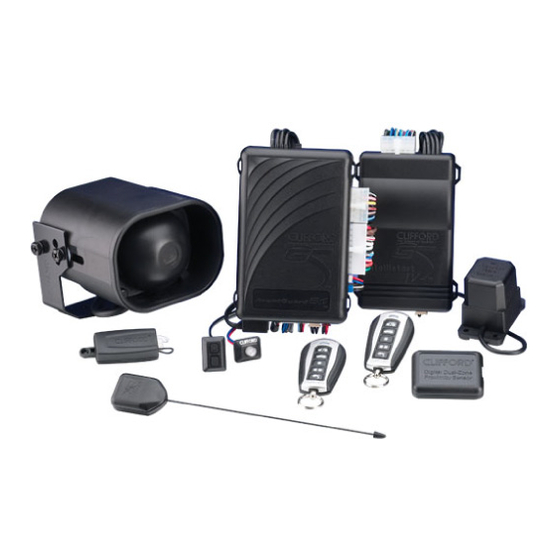
One AvantGuard 4 Control Unit
One Self-Powered SmartSiren 4
One Wireless Immobilizer
One NightVision Light Sensor
One IntelliStart 4 Control Unit
Two remote transmitters
Avant Guard 4/699
Standard Features of the AvantGuard 4
System Components
One Extended Range Receiver
One LED
One PlainView 2 Coded Valet Switch
One Digital Tilt/Motion Sensor
One Warranty Card
One Owner's Manual
One Wireless Immobilizer Location Form
One Hardware Kit
Two Window Decals
One Digital Dual-Zone Proximity Sensor 4
User-Selectable AutoUnLock
Remote Panic with Smart Locking/Unlocking
Integrated Electronic Timer
Built-In Dual Parking Light Flasher with Onboard Relay
Remote-Controlled Courtesy Lighting
Smart Remote Trunk Release
Patented Smart AutoTesting™
Patented Malfunction AutoBypass™ with
AutoReMonitoring
Enhanced User-Selectable AutoArming
AutoArm & Lock
Eight-Event TotalRecall™
Patented Smart Prior Intrusion Attempt Alert
Clear All Remotes
Multiple-Car Control
High-Luminescence LED Status Indicator with Automatic
Battery-Saving Mode
Multiple Sensor/Trigger Inputs
Patented SmartPowerUp™ 2
Full-Time SecureAccess™ Programming
Advanced CMOS Microcomputer
Patented Remote Control Code Learning and
Multiremote Recognition
Pre-Loomed Wiring
Three Accessory Outputs with Selectable Output Types
AutoActivation of Auxilliary Output
Installer-Selectable Door Ajar/Delayed Courtesy Lights
Prewired LED, Sensor, Siren, Extended Range Receiver,
and PlainView 2 Switch Connectors
1
Advertisement
Table of Contents

Related Manuals for Clifford AvantGuard 4


Summary of Contents for Clifford AvantGuard 4
-
Page 1: System Components
Standard Features of the AvantGuard 4 Lifetime Warranty User-Selectable AutoUnLock His & Hers ACG™ 2 (Anti-CodeGrabbing™) Remote Remote Panic with Smart Locking/Unlocking Controls Integrated Electronic Timer Extended Range Receiver Built-In Dual Parking Light Flasher with Onboard Relay Audible Low Remote Control Battery Warning... - Page 2 AvantGuard 4 Control Unit: Wiring Description for the 12-Pin Pigtail Connector Pin Color Con nects to Red/White Battery positive (30-amp fuse) headlight input (+) White/Orange Window Switch 2 Violet Window Motor 1 White/Violet Window Switch 1 Battery positive (30-amp fuse) window input (+)
- Page 3 Avant Guard 4/699...
- Page 4 AvantGuard 4 Control Unit: Wir ing De scrip tion for the 24- Pin Connector Pin Color Con nects to Red/Black Optional OmniSensor output (+5v) White/Blue Proximity Sensor input Violet LED output (+) Tilt Sensor and siren supply (+12v) Blue/Yellow windshield wiper input (-)
- Page 5 Avant Guard 4/699...
- Page 6 Blankic transmission, connect to reverse light / manual, connect to emergency brake light 11 Blue/White Brake light input (+) 12 Black/Gray RPM Input AvantGuard 4 Con trol Unit: Wir ing Description for the 14- Pin Con nec tor Pin Color Con nects to Blue/White Brake light input/output...
- Page 7 Avant Guard 4/699...
-
Page 8: Door Trigger/Interior Light Supply
Control Unit and Extended Range Receiver The AvantGuard 4 con trol unit must be in stalled in side the ve hi cle. Un der no cir cum stances should the unit be in stalled un der the hood or other simi larly hos tile en vi ron ment. -
Page 9: Parking Lights
2. Start the engine, then cut the ignition wire. The engine should stop running. 3. As shown on page 3, connect the WHITE/BROWN wire of the AvantGuard 4 to the key side of the cut ignition line. 4. Connect the GREEN/BLUE wire of the AvantGuard 4 and the GREEN/BLUE wire of the IntelliStart 4 to the engine side of the cut ignition line. - Page 10 If the po lar ity is nega tive when the light turns off, con nect the BLUE/BLACK wire to this wire. Brake Lights The AvantGuard 4 monitors the brake light to prevent an unauthorized driver from driving the car. The brake light input wire MUST be connected and brake light must be in working condition.
-
Page 11: Trunk Trigger
The wires noted be low are to dis arm a ve hi cle’s fac tory alarm sys tem to per mit re mote start ing. For more in for ma tion on the ve hi cle on which you are in stall ing the AvantGuard 4, down load this in for ma tion from our www.clif ford dealer.com web site, our Auto Fax serv ice or ring our Dealer... -
Page 12: Rpm Monitoring
6. Attach the six fuseholders to the positive battery terminal cable clamp using the supplied ring connectors. 7. Use ring connectors to attach the two BLACK wires from the AvantGuard 4 and the IntelliStart 4 to the negative battery terminal cable clamp. - Page 13 MANDATORY RPM PROGRAMMING Note: This MAN DA TORY pro gram ming step must be com pleted for the AvantGuard 4 to op er ate prop erly. 1. Drive the vehicle to a nearby open area and allow the engine to warm-up until the RPMs drop to the normal idle speed.
-
Page 14: Remote Control Operation
The AvantGuard 4 comes with two ergonomically designed remote controls: a 16-channel master remote and a 4-channel secondary “companion” remote. Up to a total of four AvantGuard 4 type remote controls can be added to the AvantGuard 4 system. Due to... -
Page 15: Sensor Adjustment
(you will hear 3 chirps). 5. Repeat the preceding steps as required. An improperly adjusted sensor will cause the AvantGuard 4 to false alarm or not respond properly to a genuine threat. Keep in mind that you may need to reposition the sensor, possibly after the customer has had the system for several days. -
Page 16: Fact-False Alarm Control And Test
FACT—False Alarm Control and Test The system microprocessor automatically checks for another activated sensor or trigger before sounding the siren a second time, thus preventing any further false alarms. If you wish to test FACT, simply: 1. Arm the sys tem with the re mote con trol. 2. -
Page 17: Using The Cliffnet Wizard Pro Installation Software
Programmable Features AvantGuard 4 comes from the factory with its features preprogrammed as noted in bold letters in the following tables. Some features can be programmed by the installer or the user, others can only be programmed by the installer. There are two tables provided which define the user-programmable and installer-programmable features. -
Page 18: Installer-Programmable Features
Select the row and column number, then transmit the unused button on the other remote that you want to use to perform that function. The AvantGuard 4 will respond with the same number of chirps as the row number. -
Page 19: System Checklist & Troubleshooting
System Checklist & Troubleshooting The fol low ing check list and trou ble shoot ing tips will as sure that you have in stalled the AvantGuard 4 cor rectly. If the sys tem does not re act as noted, fol low the trou ble shoot ing tip(s) de noted with a black box be low that item, then re peat the step. Each suc ces sive step re quires that the pre vious step has been com pleted as in di cated. - Page 20 Two flashes. This is the correct response, proceed to step 5. One flash. If the Parking lights flash only once, the AvantGuard 4 had pre vi ously AutoArmed it self pas sively and by press ing but ton 1 the sys tem dis armed (re mote dis arm ing is ac knowl edged with one Parking light flash). Re peat step 1.
- Page 21 No flashes. If the LED does not flash, ver ify that the LEDs VIO LET and BLACK wires are sol idly con nected to the same color wires on the AvantGuard 4’s wire loom. Warn ing: This is a 2- volt LED, test ing with 12 volts will de stroy the LED.
- Page 22 Stand approximately 100 feet from the vehicle and use the remote control to arm and disarm the system. The AvantGuard 4 will re spond with the pre vi ously noted in di ca tions for arm ing and dis arm ing. If not: Re po si tion the external receiver as high as possible high up un der the dash, or as high as possible in the windshield pillar and as far as pos si ble from heavy wire looms and metal.
- Page 23 Step 16. Test the Black Jax anti- carjacking fea ture. Refer to the System Check section in the BlackJax 4 section of this binder. Step 17. Test the Digi tal/Tilt Mo tion Sen sor. Arm the system and wait for 10 seconds (wait two-minutes if the wireloop delay was cut). Using a jack, raise the vehicle slowly and the alarm will trigger at 1 degree.
- Page 24 User’s Manual must be given to the customer. Wireless Immobilizer Location Record. One copy is for your records. One copy is for the customer. Adhere the Clifford window decals to the vehicle’s windows. Step 22. Dem on strate Ba sic Sys tem Operation Remote Operations:...