JVC RX-5000VBK Instructions Manual
Audio/video control receiver
Hide thumbs
Also See for RX-5000VBK:
- Instructions manual (55 pages) ,
- Service manual (16 pages) ,
- Instructions manual (30 pages)
Table of Contents
Advertisement
AUDIO/VIDEO CONTROL RECEIVER
RX-5000VBK
POWER
CD
TV
VCR
AUDIO
TAPE/MD
DELAY
TEST
SURROUND
5
1
2
3
EFFECT
FM/AM
– CENTER +
4
5
6
VCR
– REAR•L +
5
7/P
8
9
SOUND
MENU
DVD
CONTROL
– REAR•R +
10
+10
ENT
DVD MULTI
CD-DISC
TV VOL.
–
+
RX-5000V
PHONO
TV/VIDEO
TV CH
–
+
STANDBY
ONE TOUCH
OPERATION
+
+
POWER
VOLUME
VCR CH
MUTING
–
–
£
SLEEP
8
4
4
1
1
7
RM-SR558U REMOTE CONTROL
SPEAKERS
PHONES
1
_ ON
AUDIO/VIDEO CONTROL RECEIVER
DVD MULTI
DVD
VCR
FM
CD
PHONO
TAPE/MD
AM
2
SOURCE NAME
— OFF
INSTRUCTIONS
MASTER VOLUME
–
+
BASS BOOST
ADJUST
SETTING
MEMORY
SURROUND
MULTI CURSOR
ONE TOUCH OPERATION
INPUT ATT.
For Customer Use:
Enter below the Model No. and Serial
No. which are located either on the rear,
bottom or side of the cabinet. Retain this
information for future reference.
Model No.
Serial No.
LVT0384-001A
[J]
Advertisement
Table of Contents

Related Manuals for JVC RX-5000VBK


Summary of Contents for JVC RX-5000VBK
- Page 1 AUDIO/VIDEO CONTROL RECEIVER RX-5000VBK POWER AUDIO TAPE/MD DELAY TEST SURROUND EFFECT FM/AM – CENTER + – REAR•L + SOUND MENU CONTROL – REAR•R + DVD MULTI CD-DISC TV VOL. – RX-5000V AUDIO/VIDEO CONTROL RECEIVER PHONO TV/VIDEO TV CH – STANDBY...
- Page 2 No obstructions in 10 cm from the sides. No obstructions in 10 cm from the top. No obstructions in 15 cm from the back No obstructions, place on the level surface. Spacing 15 cm or more RX-5000VBK cause harmful interference Front...
-
Page 3: Table Of Contents
Available DSP Modes According to the Speaker Arrangement .. 16 Adjusting the 3D-PHONIC Modes ... 17 Adjusting the DAP Modes ... 17 Adjusting the Surround Modes — Dolby Surround and JVC Theater Surround ... 18 Activating the DSP Modes ... 19 Using the DVD MULTI Playback Mode ... -
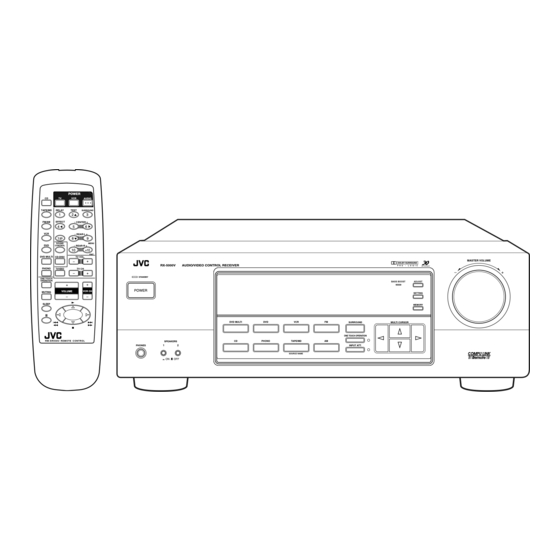
Page 4: Parts Identification
Parts Identification Become familiar with the buttons and controls on the receiver before use. Refer to the pages in parentheses for details. RX-5000V AUDIO/VIDEO CONTROL RECEIVER STANDBY POWER SPEAKERS PHONES _ ON — OFF POWER AUDIO TAPE/MD DELAY TEST SURROUND FM/AM EFFECT –... -
Page 5: Getting Started
Getting Started This section explains how to connect audio/video components and speakers to the receiver, and how to connect the power supply. Before Installation General • Be sure your hands are dry. • Turn the power off to all components. •... -
Page 6: Connecting The Speakers
AM Antenna Connections Snap the tabs on the loop into the ANTENNA slots of the base to assemble the FM 75 AM loop. COAXIAL LOOP AM Loop Antenna Outdoor single vinyl-covered wire Turn the loop until you have the best reception. Notes: •... -
Page 7: Connecting Audio/Video Components
Connecting the subwoofer speaker You can enhance the bass by connecting a subwoofer. Connect the input jack of a powered subwoofer to the SUBWOOFER OUT jack on the rear panel, using a cable with RCA pin plugs. Powered subwoofer Connecting Audio/Video Components You can connect the following audio/video components to this receiver using cables with RCA pin plugs (not supplied). - Page 8 Video component connections Use the cables with RCA pin plugs (not supplied). Connect the white plug to the audio left jack, the red plug to the audio right jack and the yellow plug to the video jack. TV (as the monitor) VIDEO MONITOR (REC)
-
Page 9: Connecting The Power Cord
Connecting the Power Cord Before plugging the receiver into an AC outlet, make sure that all connections have been made. Plug the power cord into an AC outlet. Keep the power cord away from the connecting cables and the antenna. The power cord may cause noise or screen interference. We recommend that you use a coaxial cable to connect the antenna, since it is well-shielded against interference. -
Page 10: Basic Operations
Basic Operations The following operations are commonly used when you play any sound source. Turning the Power On and Off (Standby) On the front panel: To turn on the power, press POWER. The STANDBY lamp goes off. The name of the current source (or station frequency) appears on the display. -
Page 11: Adjusting The Volume
Adjusting the Volume On the front panel: To increase the volume, turn MASTER VOLUME clockwise (+). To decrease the volume, turn it counterclockwise (–). • When you turn MASTER VOLUME rapidly, the volume level also changes rapidly. • When you turn MASTER VOLUME slowly, the volume level also changes slowly. -
Page 12: Attenuating The Input Signal
Attenuating the Input Signal When the input level of the playing source is too high, the sounds will be distorted. If this happens, you need to attenuate the input signal level to prevent the sound distortion. On the front panel ONLY: Press INPUT ATT. -
Page 13: Basic Settings
Basic Settings Some of the following settings are required after connecting and positioning your speakers in your listening room, while others will make operations easier. Changing the Source Name When you have connected an MD recorder to the TAPE/MD jacks on the rear panel: Change the source name shown on the display when you select the MD recorder as the source. -
Page 14: Storing The Basic Settings And Adjustments - One Touch Operation
Storing the Basic Settings and Adjustments — One Touch Operation JVC’s One Touch Operation function is used to assign and store different sound settings for each different playing source. By using this function, you do not have to change the settings every time you change the source. -
Page 15: Receiving Radio Broadcasts
Receiving Radio Broadcasts You can browse through all the stations or use the preset function to go immediately to a particular station. Tuning in Stations Manually On the front panel ONLY: 1. Press FM or AM. The last station of the selected band is tuned •... -
Page 16: Selecting The Fm Reception Mode
To tune in a preset station On the front panel: 1. Press FM or AM. The last station of the selected band is tuned • The MULTI CURSOR % / fi / @ / # buttons can be now used for operating the tuner. 2. -
Page 17: Using The Dsp Modes
Using the DSP Modes The built-in Surround Processor provides three types of the DSP (Digital Signal Processor) mode — 3D-PHONIC mode, DAP (Digital Acoustic Processor) mode and Surround mode (Dolby Pro Logic and JVC Theater Surround). 3D-PHONIC modes The 3D-PHONIC mode gives you such a nearly surround effect as it... -
Page 18: Available Dsp Modes According To The Speaker Arrangement
Available DSP Modes According to the Speaker Arrangement Available DSP modes will vary depending on how many speakers are used with this receiver. Make sure that you have set the speaker information correctly (see page 11). Speaker arrangements Front speaker Front speaker Center speaker... -
Page 19: Adjusting The 3D-Phonic Modes
Adjusting the 3D-PHONIC Modes Before you start, remember... • Make sure that you have set the speaker information correctly (see page 11). • There is a time limit in doing the following steps. If the setting is canceled before you finish, start from step 1 again. On the front panel: 1. -
Page 20: Adjusting The Surround Modes - Dolby Surround And Jvc Theater Surround
• There is a time limit in doing the following steps. If the setting is canceled before you finish, start from step 1 again. • You can only adjust the effect level when selecting JVC Theater Surround. • You can only adjust the rear and/or center speaker output levels when you have connected rear speakers and/or a center speaker and have set “REAR SPK”... -
Page 21: Activating The Dsp Modes
• Each time you press the button, the DSP modes change. (See page 16 for more details) 2. Select and play a sound source. • To enjoy the 3D-PHONIC, Dolby Surround, and JVC Theater Surround, play back a software which was processed with MULTI CURSOR... -
Page 22: Using The Dvd Multi Playback Mode
Using the DVD MULTI Playback Mode This receiver provides the DVD MULTI playback mode for reproducing the analog discrete output mode of the DVD player. Before playing back a DVD, refer also to the manual supplied with the DVD player. Activating the DVD MULTI Playback Mode You can adjust the DVD MULTI playback mode while playing back a DVD using the analog discrete output mode on the DVD player. -
Page 23: Compu Link Remote Control System
COMPU LINK Remote Control System The COMPU LINK remote control system allows you to operate JVC audio components through the remote sensor on the receiver. To use this remote control system, you need to connect JVC audio components through the COMPU LINK-3 (SYNCHRO) jacks (see below) in addition to the connections using cables with RCA pin plugs (see page 5). -
Page 24: Operating Jvc's Audio/Video Components
Operating JVC’s Audio/Video Components You can operate JVC’s audio and video components with this receiver’s remote control, since control signals for JVC components are preset in the remote control. IMPORTANT: To operate JVC’s audio components using this remote control: • You need to connect JVC audio components through the COMPU LINK-3 (SYNCHRO) jacks (see page 21) in addition to the connections using cables with RCA pin plugs (see page 5). - Page 25 • Aim the remote control directly at the remote sensor on the VCR, DVD player or TV, not on the receiver. • Some JVC VCRs can accept two types of the control signals — remote code “A” and “B.” Before using this remote control, make sure that the remote control code of the VCR connected to the VCR jacks is set to code “A.”...
-
Page 26: Troubleshooting
Troubleshooting Use this chart to help you solve daily operational problems. If there is any problem you cannot solve, contact your JVC service center. PROBLEM The display does not light up. No sound from speakers. Sound from one speaker only. -
Page 27: Specifications
1 kHz, with no more than 0.8 % total harmonic distortion. Total Harmonic Distortion (8 ohms, 1 kHz): 0.8 %* at 100 watts output (* Measured by JVC Audio Analysis System) Audio Audio Input Sensitivity/Impedance (1 kHz): PHONO (MM): 2.7 mV/47 k ohms... - Page 28 Sophisticated electronic products may require occasional service. Just as quality is a keyword in the engineering and production of the wide array of JVC products, service is the key to maintaining the high level of performance for which JVC is world famous. The JVC service and engineering organization stands behind our products.
- Page 29 WHAT WE WILL DO: If this product is found to be defective, JVC will repair or replace defective parts at no charge to the original owner. Such repair and replacement services shall be rendered by JVC during normal business hours at JVC authorized service centers.
- Page 30 VICTOR COMPANY OF JAPAN, LIMITED 1299HIMMDWJEIN...