
Related Manuals for Polaroid 600SE


Summary of Contents for Polaroid 600SE
- Page 1 Repair Manual 600SE Professional Pack Film Camera June 1967 Americas Business Center Technical Services 201 Burlington Road Bedford MA 01730 TEL: 1.781.386.5309 FAX: 1.781.386.5988...
-
Page 2: Table Of Contents
Removing Covers from Rangefinder Assembly (Model 600 Only) ......Removing Framing Mask Assembly (Model 600SE Only) ........Removing Framing Screen from the Parallax Frame (Model 600SE) ..... Removing Framing Mask Assembly (Model 600) ..........Removing Framing Screen from the Parallax Frame (Model 600) ...... - Page 3 Removing 127mm Lens Assembly from the Model 600 Camea ......Removing the Springs from the Bayonet (Model 600SE) ........Removing the Bayonet (Model 600SE) ..............Removing Locking Lever from Front Panel of Model 600SE Camera ....Removing the Front Panel Leg ................Removing Front Panel ...................
- Page 4 Locking Accessory Viewfinder on to Camera........... Removing Film Holder and Lens Assembly, Model 600SE Camera ....Hand Grip Removal ..................Removing Hand Grip Flash Shoe and Cable Release Rack (Model 600SE) ... Hand Grip Exploded View ................Removing Viewfinder Selector Switch..............
- Page 5 4-31 Removing the 127mm Lens Assemblly from Model 600 Camera ..... 4-32 Removing Springs from Bayonet ..............4-33 Removing the Bayonet from the Model 600SE Camera ........4-34 Removing Locking Lever from Front Panel of Model 600SE Camera ....4-35 Removing Front Panel Leg ................4-36 Removing Front Panel ..................
- Page 6 Special Tools ....................List of Tables Table Page 1-1 Differences Between the Model 600 and 600SE Cameras ........ 1-2 Lenses ......................1-3 Polaroid Land Pack Films for Model 600/600SE Cameras ....... 5-1 Model 600/600SE Camera Tests ..............5-2 Allowable Range of Shutter Speeds ..............
- Page 7 NOTES...
-
Page 8: Description
1- Description General The Polaroid Land Models 600 and 600SE Professional Pack Film Cameras are non-folding cameras designed for the professional photographer. They use a removable Polaroid pack film holder which accommodates Polaroid pack film holder which accommodates Polaroid type 100/600 Land Film. -
Page 9: Differences Between Models
Top Cover Rangefinder Assembly Face Plate Camera Body RF/VF Window Cover Figure 1-2. Location of the rangefinder assembly Differences Between Models A summary of the differences between the two models is contained in Table 1-1. The basic camera is 7" high, 7" deep and 9" wide (18cm X 18cm X 18cm X 24cm) (including hand grip). The weight including the pack film holder is about five pounds (2.2 kg). - Page 10 75mm: 1 pound, 6 ounces; (.6 kg) * 75mm viewfinder: 6 ounces; (1.7 kg) * The height of the model 600SE with the 75mm viewfinder mounted onto the accessory shoe is 9 1/2 inches; (25 cm). WEIGHTS: Film holder without film pack: 14 ounces; (.4 kg). Film pack: 4 ounces; (11 kg).
-
Page 11: Model 600Se Camera Features
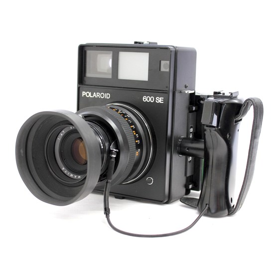
Mount Film Holder Lock Hand Strap Bayonet Cable Release Tripod Socket Lens Mount Lens Release Button Figure 1-3. Model 600SE camera features Neck Strap Accessory Shoe Viewfinder Windows Hand Strap (Adjustable) Eyecup Shutter Release Hand Grip Neck Strap Eyelets Depth of field Scale... -
Page 12: Lenses
The Model 600 Camera has a 127mm f/4.7 lens (Figures 1-5 through 1.7). Two additional interchangeable lenses are available for Model 600SE (Table 1-2). The interchangeable lenses use a bayonet type mount for attaching to the camera body. A lens release button locks the lens to the camera body. - Page 13 150mm lens fields-of-view. A 75mm parallax corrected viewfinder supplied with the 75mm lens can be mounted on top of the rangefinder area of the model 600SE camera body (Figure 1-7). The model 600 camera rangefinder/viewfinder has framing lines for the 127mm lens only.
- Page 14 Lens Cap Rubber Lens Hood Lens Assembly Rear Lens Figure 1-6. 150mm f/5.6 portrait lens Lens Cap Rubber Lens Hood Lens Assembly Accessory Wide Angle Viewfinder Rear Lens Figure 1-7. 75mm f/5.6 portrait lens with wide angle viewfinder...
-
Page 15: Polaroid Pack Film Holder
Film Holder - The model 73 Land film holder is used to hold the pack film in the camera. The films used in model 600/600SE cameras are described in Table 1-3. Sliding locks hold the film holder to the camera body. -
Page 16: Polaroid Land Pack Films For Model 600/600Se Cameras
Table 1-3. Polaroid Land pack films for model 600/600SE cameras Film Speed (approx. Description Type ASA/DIN equiv.) Types 668/108 75 ASA/20 DIN These films yield a positive color print. Polacolor 2 They are balanced for use in average daylight and with electronic flash units approximating average daylight (5500K). -
Page 17: Operation
2 - Operation Steps to Operate the Camera (Figure 2-1) • Mount flash attachment. • Select and mount lens (model 600SE only). • Position viewfinder selector switch to 127 or 150. • Mount filter. • Load film. • Remove dark slide. -
Page 18: Operating The Professional Pack Film Land Camera
2. Set the shutter speed and lens aperture. 1. Be sure the dark is removed. Look through the viewfinder to frame the picture. Set the focus. Measure the light. 3. Read the distance to the object 4. Shoot! on the distance scale. - 7 Feet - 5 Feet - 4 Feet... -
Page 19: Viewing And Focusing With The 127Mm And 150Mm Lenses
The image shown in Figure 2-3 can be seen by looking through the eyepiece of either the model 600 or model 600SE cameras. In the model 600SE camera the viewfinder frame is adjustable for the 127mm and 150mm lenses. The number that appears just below the top right framing line indicates the lens that has been selected. -
Page 20: Looking Through The Eyepiece
When focusing beyond 10 feet, the picture is composed within the limits of the eight framing dots. The Models 600 and 600SE are equipped with a coincidence-type rangefinder in which two images come together within a circle when in focus. Familiarize yourself with it by setting the lens at infinity. -
Page 21: Operation Of The Viewfinder
The construction of the viewfinder built into the model 600 and 600SE camera is shown in Figure 2-4. The model 600 has framing lines for the 127mm lens only. The model 600SE has two sets of framing lines and lens indicators for the 127mm and 150mm lenses. -
Page 22: Viewing And Focusing With The 75Mm Lens And Accessory Viewfinder
On the model 600SE, a metal mask (with a pattern of holes) blocks the light from one of the framing images. Moving the viewfinder selector switch moves this metal mask to reveal one framing image on the film, and blocks the other framing image. -
Page 23: Locking Accessory Viewfinder On To Camera
Unlock the viewfinder by turning the locking screw opposite to the direction of the arrow on the viewfinder. When fully unlocked, the locking screw can be seen in its topmost position. If this locking screw is partially down, it will prevent the viewfinder from being fully seated on the accessory show. -
Page 24: Troubleshooting
3 - Troubleshooting Persons unfamiliar with Polaroid Model 600 and 600SE cameras should read Sections 1 and 2 to gain an adequate background of camera operation and features. Reference to these troubleshooting charts should be sufficient to diagnose camera problems in most cases. The methods of implementing the corrective actions are detailed in Sections 4 and 5. - Page 25 Problems Evidenced in Pictures (Con't) Problems Probable Cause Corrective Action Picture fogged 1. Sponge filters missing 1. Replace filler sponges on camera (light leak). from camera body. body 2. Film holder door hinge loose 2. Repair or replace door on film or broken.
- Page 26 Problems with Film Holder Problems Probable Cause Corrective Action Bad spreads. 1. Rollers dirty. 1. Clean rollers (instruct customer). 2. Rollers nicked or scratched 2. Replace A-11 mini-roller assembly. Film tearing 1. Exit door malformed 1. Replace film holder. (not opening properly). 2.
-
Page 27: Camera Checkout
Examine action of film holder locks on both sides of camera. d. Inspect bayonet lens mount for damage or defective springs. e. Examine the viewfinder selector switch on the Model 600SE camera. Move the switch to the 127 and 150 positions. Number in framing image should agree with selected number. - Page 28 6. Examine the Rangefinder/Viewfinder (RF/VF) Inspect the lenses to be sure they are not cracked, scratched or dirty. Move lens focus ring while looking through eyepiece. Inspect for smooth tracking of lens setting by the rangefinder. Perform parallax framing and tracking discrepancy tests. 7.
-
Page 29: Disassembly/Assembly Procedures
4- Disassembly and Assembly General Disassembly and reassembly of both the model 600 and 600SE cameras is covered in this section. Instructions apply to both models unless otherwise indicated. The differences between model 600 and model 600SE camera are covered in Section 1. -
Page 30: Hand Grip Removal
Hand Grip Removal (Figure 4-2) The model 600SE hand grip has a cable release holder and flash shoe attached. It also has a black chrome cable release. The model 600 has a chrome cable release. Otherwise the had grips are the same. -
Page 31: Removing The Hand Grip Flash Shoe (Model 600Se)
Remove the four (4) screws holding the shoe and the cable release rack. Stopper Screw Shoe Cover Screws (4) Hand Grip Flash Shoe Cable Release Rack Hand Grip Figure 4-3. Removing hand grip flash shoe and cable release rack (model 600SE) -
Page 32: Disassembling The Hand Grip
Disassembling Hand Grip (Figure 4-4) a. Remove screw and belt plate (2); fold grip belt (8) back out of the way. b. Remove two screws (3) and separate right hand grip (4) from the assembly. c. Slide plate (5) off of grip (4) and remove screw (6), belt plate (7), and grip belt (8). d. -
Page 33: Removing The Rangefinder Covers
The viewfinder window cover and the top cover can be removed to allow inspection and adjustment. On the model 600SE camera, move the viewfinder indicator to the 150 position to give access to an anchor screw securing the rangefinder assembly to the camera body. Remove screw and button shown in Figure 4-5. -
Page 34: Releasing Screw From Holder Plate
Releasing Screw from Holder Plate (Figure 4-7) Lay camera on a soft surface, with viewfinder windows facing up. Remove Phillips head screw shown in Figure 4-7. Holder Plate Screw Figure 4-7. Removing holder plate screw from viewfinder window Removing Top Cover (Figure 4-8) Complete part removal shown in Figures 4-5 through 4-7. -
Page 35: Removing The Accessory Shoe
The viewfinder assembly is now partially exposed for inspection, cleaning or adjustment (Figure 4-9) Note: Do not turn screws without first determining if they are adjusting screws. Refer to Section 5 before attempting adjustments. Near Distance Range Adjusting Screw Infinity Range Adjusting Screw Topside Adjusting Screw... -
Page 36: Removing The Rangefinder Assembly
Removing Rangefinder Assembly (Figures 4-11 through 4-13) On the model 600SE, slide the bar marked 127 150 away from the eyepiece. Unhook spring. Remove anchor screw. Anchor Screw Spring Figure 4-11. Unhook spring, remove anchor screw Place camera in vertical position. Remove two screws, shown in Figure 4-12. -
Page 37: Removing Rangefinder Assembly From Camera Body
Lift rangefinder assembly from the camera body as shown in Figure 4-13. Anchor Screws Screws (2) Rangefinder Assembly Camera Body Figure 4-13. Removing rangefinder assembly from camera body Note: Do not loosen the eccentric screws or the parallax relay lever screw, without referring to instructions covering parallax adjustment in Section 5 (Figure 4-14). -
Page 38: Removing Ghe Rangefinder/Viewfinder Windows
Framing Mask (Metal) Rangefinder Window (Glass) Screen Glass Objective Windows (Glass) Mask (Metal) Figure 4-15. Removing rangefinder/viewfinder windows Removing Viewfinder Selector (Model 600SE Only) (Figure 4-16) Remove two screws as shown in Figure 4-16. Guide Screw Viewfinder Selector Screw (2) Rangefinder... -
Page 39: Disassembly Of Viewfinder Selector (Model 600Se Only)
Detent Spring Figure 4-17. Parts of the viewfinder selector Removing Covers from Rangefinder Assembly (Model 600SE Only) (Figure 4-18) Pry plate from eyepiece assembly area. Remove single screw, shown in Figure 4-18. Use tweezers to gently loosen sponge filler from eyepiece assembly area. Lift cover from rangefinder. -
Page 40: Removing Covers From Rangefinder Assembly (Model 600 Only)
Plate Assembly Eyepiece Assembly Figure 4-18. Removing cover from rangefinder assembly (model 600SE) Removing Covers from Rangefinder Assembly (Model 600 Only) Pry plate from eyepiece assembly area. Remove single screw, shown in Figure 4-19. Use tweezers to gently loosen sponge filler from eyepiece assembly area. Use tweezers to gently lift paper cover from rangefinder casting. -
Page 41: Removing Framing Mask Assembly (Model 600Se Only)
Removing Framing Mask Assembly (Model 600SE Only) It is possible to remove and repair the framing mask spring (keeping the metal mask in tension against the film framing mask) without disassembly of the rangefinder/viewfinder. Figure 4-20 shows the spring. It is accessible after the viewfinder window cover and viewfinder windows have been removed (Figures 4-6 and 4-15). -
Page 42: Removing Framing Screen From The Parallax Frame (Model 600Se)
Removal of the film framing screen from the parallax frame will require realignment of the framing images and adjustment of the mask and framing screen positions. Screw (2) Parallax Frame Screw Slot Pivot Screw Screw Framing Screen Washer Figure 4-22. Removing framing screen from parallax frame (model 600SE) -
Page 43: Removing Framing Mask Assembly (Model 600)
Removing Framing Mask Assembly (Model 600) ( Figure 4-23) Note: Removal of the film framing screen from the parallax frame will require realignment of the framing images and adjustment of the mask position. Remove the top screw and slip the framing mask assembly up until the lower slot is free from the lower screw. -
Page 44: Removing The Parallax Lever Assembly From The Rangefinder Assembly
Removing Parallax Lever Assembly from Rangefinder ( Figure 4-25) Remove the connector screw which holds the two levers together. Loosen and remove the shaft while holding the spring loaded lever assembly. Turn the rangefinder assembly over and remove the pivot screw holding the parallax lever (upper). At Reassembly, reset spring tail against objective lens. -
Page 45: Removing Objective Lens Assembly
Removing Eyepiece Assembly (Figure 4-27) The eyepiece ring can be screwed off to allow cleaning of the eyepiece concave lens. The plate is glued to the housing. Use a knife to lift an edge or corner. Insert a thin metal blade under the plate. -
Page 46: Removing Mirror Assembly From The Rangefinder Assembly
Removing Mirror Assembly from Rangefinder Assembly (Figure 4-28) Note: Removal of this assembly will require readjustment of the rangefinder (See Section 5). The leaf spring position and the upper pivot position are fixed by shellac or other adhesive. Remove excess adhesive after removing parts. Cement these parts into a fixed position after the rangefinder has been adjusted. -
Page 47: Removing Inner Cover From Front Panel
Remove six (6) Phillips head screws. Lift cover from front panel. On the model 600SE camera, the lens release button assembly is part of the cover being removed. Do not remove the lens release button. It is not a listed spare part. Clean the contact surface before reassembly. -
Page 48: Removing Springs From Bayonet
Field Scale (in Twelve O'Clock Position) Screws (6) Washer (3) 127MM Lens Assembly Figure 4-31. Removing 127mm lens assembly from model 600 camera Model 600SE Camera Spring (4) Heel End of Spring Spring Slot (4) Screw (8) Bayonet Figure 4-32. Removing springs from bayonet... -
Page 49: Removing The Bayonet (Model 600Se)
Lever Tip Screws (6) Phillips Head Figure 4-33. Removing bayonet from model 600SE camera Removing Locking Lever from Front Panel (Model 600SE) ( Figure 4-34) Remove bayonet as shown in Figure 4-33. Use Phillips screwdriver to remove two screws. Lift out lever. -
Page 50: Removing The Front Panel Leg
Screw Spring Finger Locking Lever Spring Stud Figure 4-34. Removing locking lever from front panel of model 600SE camera Removing Front Panel Leg (Figure 4-35) The front panel leg may be removed at any camera assembly level. Reassemble by observing fit relationship between boss on bottom of front panel leg and recess in bottom of front panel. -
Page 51: Removing Front Panel
Removing Front Panel ( Figure 4-36) Remove covers as shown in Figures 4-29 and 4-30. The screws are glued in place. Select a proper fitting Phillips screwdriver to fit the screws in the deep holes in the front panel. Remove eight (8) screws. Lift off front panel. Camera Body Deep Hole for Screws... -
Page 52: Removing The Flash Gun Bracket
Removing Flash Gun Bracket (Figure 4-38) Remove two Phillips head screws. Remove bracket Removing Leatherette and Plates from Camera Body (Figure 4-38) The leatherette is a man-made material attached to a light metal backing. When removing leatherette, be sure to lift up from under the metal backing. Peel off the leatherette. Pry out plates. Replace bent parts. -
Page 53: Removing Sliding Locks
Camera Body (Removal of Tripod Socket can occur with camera assembled.) Screws (4) Tripod Socket Leatherette Figure 4-39. Removing tripod socket Removing Sliding Locks ( Figure 4-40) Carefully peel off the index mark plate. Use a knife to lift one end and slip a thin blade under the plate to break the glue joint. -
Page 54: Removing Parallax Coupling Assembly
Use a small Phillips screwdriver to remove two flat head screws from each slide lock cover. Remove the covers. Remove the hex head screws, two each side. Remove leaf springs and slide locks. Apply Lubriplate before reassembly. Note: Mark slide locks, left and right, for ease of reassembly. Inspect guide pins. -
Page 55: Removing Range Lever Assembly
Reassemble by placing spring on parallax coupling lever assembly. The position of the levers as you look up inside the camera is shown i the left side of Figure 4-41) Removing Rang Lever Assembly (Figure 4-42) Remove two (2) Phillips head screws from range lever upper. Carefully pull range lever upper off the brass centering pin of the range lever assembly. -
Page 56: Removing Range Lever Upper Spring
Removing Range Lever Upper Spring (Figure 4-43) Release spring so that both ends rest on back wall of camera body. Remove screw and spring. Range Lever Upper Parallax Range Lever Relay Lever Upper Spring Middle Lever Screw Back Wall Spring Camera Body Camera Back Wall... - Page 57 Middle Lever Spring Shaft Middle Lever Eccentric Adjustment Middle Lever Screws Base Plate Figure 4-44. Removing middle Lever Back Sealing Camera Body Sponge Front Sealing Sponge Figure 4-45. Removing camera body sponge...
-
Page 58: Removing Strap Eyelets
Removing Strap Eyelets (Figure 4-46) Use Phillips screwdriver to remove three (3) screws from each strap eyelet. Lift off strap eyelet. Remove adhesive and clean parts before reassembly. Screws Strap Eyelet Figure 4-46. Removing strap eyelets Removing Flash Gun Mounting Socket (Figure 4-47) Use Phillips screwdriver to remove four screws holding flash gun mounting socket to camera body. -
Page 59: Removing Grip Holder Socket
Removing Grip Holding Socket (Figure 4-48) Use a 2.5mm Allen wrench to remove three screws holding grip holder socket to camera body. Camera Body Grip Holder Socket Washers (3) Screws (3) Figure 4-48. Removing grip holder socket Removing Bottom Plates (Figure 4-49) Use Phillips screwdriver to remove three screws from each bottom plate and lift off the plates. -
Page 60: Removing The Pc Flash Connector Socket
Release contact lug from PC flash connector socket as shown in Figure 4-50. Remove the lens assembly from the camera body, as previously described for model 600SE. The shutter is held to the lens assembly by the retaining nut shown in Figure 4-51. The lens spanner wrench, special tool no. - Page 61 Screw Special Tool No. 12459 Screw Screw Light Baffle No. 1 Coupling Light Baffle Rear Lens No. 2 Assembly Camera Body Retaining Nut Light Baffle No. 3 Figure 4-51. Loosing shutter retaining nut with special tool no. 12459 Carefully lift the front end including the shutter away from the shutter cover assembly as shown in figure 4-52.
- Page 62 shutter assembly in a plastic bag. 8 12 Note: Collimation of lens will be required after any disassembly of lens system. Cross Section of Front End of Lens Barrel Front Lens Lock Retaining Nut Ring Time Mark Ring Aperture Blades Shutter Blades Front End of Lens Barrel (6 through 13)
-
Page 63: Disassembly Of 127Mm Lens Barrel
Disassemble front end as shown in Figures 4-51 through 4-53. The assembly relationship of the rear of the lens barrel is shown in Figures 4-54 and 4-55. This disassembly is normally not required. Light Baffle #3 Depth Field Scale Ring (Model 600) Light Baffle #2 Light Baffle #1... -
Page 64: Disassembly Of 150Mm Lens Barrel
Figure 4-55. Disassembly of rear of Lens barrel, 127MM lens The 127mm lens for the model 600SE is very similar to the 127mm lens for the model 600 (Figures 4-54 and 4-55. Note the differences in the depth of field scale ring. -
Page 65: Disassembly Of Rear Of Lens Barrel, 150Mm Lens
Disassemble front end as shown in Figure 4-52. The assembly relationship of the rear of the lens barrel is shown in Figure 4-56. This disassembly is not normally required. If helicoid assembly is defective, replace lens barrel. The light baffles are glued in position. Note position and mark light baffles 1 and 2 before disassembly. -
Page 66: Disassembly Of The 75Mm Lens
Remove the front lens cap. Turn the focusing ring to the close-up position. Grip the outer edge of the front lens assembly. Twist hard in a counterclockwise direction. Unscrew front lens assembly. Clean lens. Replace front lens cap. Store lens. Note: Any disassembly of the lens system will require collimation of the lens. -
Page 67: Removing Retaining Nut From Shutter, 75Mm Lens
down. This will keep the shim washers and store for reassembly. Place the lens barrel with the rear up, as shown in Figure 4-59. Use special tool No. CCR-12459 as a spanner wrench. Loosen the retaining nut holding the shutter to the lens barrel. Use your fingers to unscrew the retaining nut. -
Page 68: Removing The Aperture Ring And Index Mark Ring
Use a thin blade screwdriver to loosen (not remove) three screws holding the aperture ring to the shutter. Grip the aperture control knob. The flexible plastic aperture ring can be pulled off the retaining washers. The ring will still be retained by the knob. Note: Be prepared to capture the click ring and steel ball. -
Page 69: Removing The Focusing Ring
Remove the rubber grip from the focusing ring. Loosen the four set screws that were hidden by the rubber grip; it may require a long soak in trichloroethylene to dissolve glue in screw threads. Remove focusing ring. Remove four screws holding retaining ring to the depth of field scale ring. Depth of Field Scale Ring Set Screws (4) Screws (4) -
Page 70: Removing 75Mm Lens, Depth Of Field Scale Ring
Ring Ring Depth of Field Scale Ring Plates (2) Screws (4) Earth Plate Screws (4) Shutter Release Ring Spring Shutter Cover Screw Figure 4-62. Removing 75MM lens, depth of field scale ring Film Holder Because of the simplicity of the Model 73 Film Holder, repairs are minimal. Those parts which may be replaced are: A) Mini-Roller Spread System;... -
Page 71: Removing Spread System Springs
Spread Pull Rotate Tool No. 11606 Figure 4-63. Removing spread system springs 5. Repeat the procedure for the other spring. Note: Before withdrawing the rollers, note that the plastic bearing blocks that support the ends of the rollers are dissimilar in both color and configuration. Observe and note where each is located. -
Page 72: Mini-Roller Spread System Disassembly/Reassembly
platform. The blocks and rollers must be pulled straight up and out of the grooves. Do not cock the rollers while withdrawing the assembly. Note: Although it may not be necessary to replace both rollers, it is necessary to replace the pair of rollers as an assembly. CAUTION Do not reinstall a bearing block that is cracked or broken. -
Page 73: B. Adapter Frame - Disassembly/Reassembly
10. Slide the spring in until the end bottoms in the cutout provided for it in the top of the bearing block. See B on Figure 4-63. 11. Remove the special tool. 12. Install the other load spring in the same manner. 13. -
Page 74: C. Bail Latch - Disassembly/Reassembly
d. Pull a sample film. e. If any light leak is found, locate its source and repair the film holder as necessary. C. Bail Latch - Disassembly/Reassembly 1. The bail latch may be removed by gently spreading it at the door busings and pulling it free. 2. -
Page 75: Testing And Adjustments
5 - Testing and Adjustments Table 5-1 lists the tests that are necessary in the repair of Model 600/600SE cameras: Table 5-1. Model 600/600SE Camera Tests Test Equipment Used Camera Adjustments Light Leak Test 150W Lamp, Replace Light Seals. 3000 ASA Film Type 107. -
Page 76: Shutter Speed Test
2. Open the shutter to the widest aperture setting, f/4.7 stop or the f/5.6 stop. Trip and test the shutter through all the speed settings from 1 second to 1/500 second. Note: Table 5-2 shows the allowable range of shutter speeds that are accepted by Polaroid Corporation. -
Page 77: Rf/Vf Parallax And Lens Collimation Tests
Infinity-Tube Tracking Test, and Near-Distance Tracking Test. The interchangeable lenses of the Model 600SE camera have different rangefinder tracking discrepancy allowances. All three lenses (75mm, 127mm, and 150mm) should be tested before decisions about adjustments are made. -
Page 78: Perfect Image Of Infinity Target Seen Through The Viewfinder At Infinity
3. Look through the viewfinder eyepiece. Aim the camera at the collimator infinity tube. Turn the lens focus ring to infinity. The image you should see is shown in Figure 5-2. The image is inverted and slanted. If the image shown in Figure 5-2 cannot be seen clearly through the viewfinder, move the camera. -
Page 79: Infinity Tube Tracking Test Procedure
5. If the base lines do not line up, remove rangefinder top cover and make any necessary topside adjustment (Figure 5-4). If necessary, use trichloroethylene to free topside adjusting screw. Turn topside adjusting screw only. Observe movement of infinity-tube-target image through the viewfinder eyepiece. - Page 80 3. Focus the loupe on focal plane plate No. CCR-12262. The focal plane plate has a flat glass surface. When this plate is loaded into the film holder on the camera, this glass surface is accurately located at the focal plane of the camera. The loupe on the plate allows you to see a magnification of an image focused through the camera lens onto this focal plane surface.
-
Page 81: Measuring Collimation Tracking Error At Infinity
Figure 5-6. Infinity-tube as seen through focal plane loupe Best Loupe Focus Image Coincidence Figure 5-7. Measuring collimation tracking error at infinity c. Measure tracking error by using a ruler or other measuring device to measure gap; Xbetween marks on the distance scale of each lens. Tracking error = " X ", cannot exceed the following limits: Lens Xmax... -
Page 82: Aiming And Framing Target Test Procedures
Leave pencil marks on the distance scale, so infinity tracking error can be compared to near distance tracking error. Before making an adjustment to the Model 600SE camera, you must compare the collimation tracking error measured sighting through each interchangeable lens. This comparison will avoid needless adjusting back and forth of the three lenses and viewfinder. -
Page 83: Camera Lined Up With Aiming Circle
Note: The same suggested distances apply to the near-distance tracking error test procedure. On the Model 600SE camera, complete tests on a single lens at the suggested tripod position., Then move tripod to next position and complete tests for the additional lenses. -
Page 84: Sighting For Parallax Test For 75Mm Lens
Viewfinder Albada Lines Target Figure 5-10. Line up albada line with framing target c. Framing for the 75mm lens is done by sighting through the 75mm accessory viewfinder, as shown in Figure 5-11. Sight through 75mm Accessory Viewfinder for Framing Only Sight through Camera Eyepiece for Coincident Image Tests... -
Page 85: Aiming Measurement
Figure 5-12. Aiming measurement 8. If the intersection is outside the aiming circle, adjust the position of the viewfinder. Note: Do not correct aiming errors by adjusting the position of the lens assembly. a. Adjust the 127mm and 150mm aiming errors to the left and right by shifting the left-to-right position of the rangefinder/viewfinder. -
Page 86: Adjusting Distance Scale On 75Mm Accessory Viewfinder
c. The aiming of the 75mm accessory viewfinder can be adjusted left or right by loosening the screws securing the accessory shoe ( Figure 5-14). Shift position of accessory shoe. Shoe Cover Stopper Screw Accessory Shoe Screws (4) Cover Holder Plate Figure 5-14. -
Page 87: Near Distance Tracking Test Procedure
Turn distance scale with your finger, until scale reading agrees with measured distance. Tighten lockscrew. If additional adjustment is required, insert shim under mounting base as shown in Figure 5-16. Shim Location Mounting Base Plate Figure 5-16. Shim adjustment to 75mm accessory viewfinder e. -
Page 88: Camera Setup For Near Distance Collimation Test
Focal Plane Plate Film Holder Seat Plate Door Open to Right Focal Plane Loupe Tripod Figure 17. Camera setup for near distance collimation test Image Coincidence Figure 18. Marking image coincidence at near distance 3. Set the camera as follows, for collimation test. The camera and tripod position should not be changed from the image coincidence position. -
Page 89: Measuring Collimation Tracking Error At Near Distance
c. Place the focal plane plate No. CRR-12262 into the film holder as if it were a film pack (Figure 5-17). Check that plate is seated to the right. Obtain sharp focus of the scratch on the focal plane. d. Set the aperture to the smallest number (largest opening). Aperture 127mm lens = f/4.7 150mm lens = f/5.6... -
Page 90: Parallax Adjustments
Verification should be done by a second observer. b. On the Model 600SE, comparison of the results of the tracking error measurements for each of the three lenses should be made, in order to determine which adjustment to make. -
Page 91: Access To Infinity Range Adjustment
Access Hole Figure 5-20. Access to infinity range adjustment Figure 5-21. RF/VF near-distance eccentric screw adjustment Coupling Pin Adjustment Screw (Rear of Lens Barrel) Figure 5-22. Location of lens barrel coupling pin adjustment... -
Page 92: Loosening Front Lens Lock Ring
6. Lens collimation adjustment. If the adjustments described in Step 5 will not bring the tracking discrepancy to within the limits listed in Step 4, adjust the position of the front lens. a. Use a lens spanner wrench to loosen the front lens lock ring (Figure 5-23). Put a few drops of trichloroethylene around the outside of the front lens lock ring. - Page 93 d. Move the camera to the aiming and framing target as shown in Figure 5-10. Look through the viewfinder eyepiece. Adjust focus until the images of the tape line coincide. Mark the distance scale. e. Look through the focal plane loupe. Slowly adjust the lens until the sharpest image is seen. Mark the distance scale.
-
Page 94: 6- Special Tools And Test Equipment
6 - Special Tools and Test Equipment The special tools listed in Table 6-1 are used to repair the model 600/600SE cameras. Table 6-1. Special Tools and Test Equipment Name Tool Number Collimator 11431 Focal Plane Plate CCR-12262 Reporter Aiming and... -
Page 95: Test Targets
Reporter Aiming and Framing Target Aiming Circle Figure 6-2. Test targets Modified Spanner Wrench Spreader (No. W6600) For Mini-Roller (No. 11606) Modified Straight Blade End Tips (No. T3790) Standard Straight Pencil Point Tips (No. T3785) Figure 6-3. Special tools...