Table of Contents
Advertisement
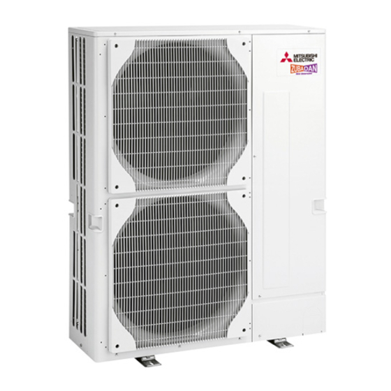
SPLIT-TYPE, HEAT PUMP AIR CONDITIONERS
TECHNICAL & SERVICE MANUAL
<Outdoor unit>
Models
PUH18EK
PUH24EK
PUH30EK
PUH36EK
PUH42EK
PUH42EK7 PUH42EK7
•The contents of LD6 in Main functions of LED
(page 13) have been revised.
•The contents of LD5 and LD6 in
TROUBLESHOOTING ACCORDING TO
CHECK CODE (page 22) have been revised.
•Refer to other manual as for Indoor Units.
•Please void OC247 REVISED EDITION-B.
PUH24EK
PUH30EK
PUH36EK
PUH42EK
Outdoor unit
1
PUH30EK
1
PUH36EK
1
1
1
CONTENTS
1. FEATURES ························································2
2. TECHNICAL CHANGE······································3
3. COMBINATION OF INDOOR AND OUTDOOR UNITS ··············4
4. PART NAMES AND FUNCTIONS·····················4
5. SPECIFICATIONS ·············································5
6. DATA··································································6
7. OUTLINES AND DIMENSIONS ························8
8. WIRING DIAGRAM··········································11
9. REFRIGERANT SYSTEM DIAGRAM ···················15
10. MICROPROCESSOR CONTROL ···················16
11. TROUBLESHOOTING·····································20
12. DISASSEMBLY INSTRUCTIONS····················25
13. PARTS LIST ····················································29
C
US
No. OC245
REVISED EDITION-C
2
2
TM
Advertisement
Table of Contents

Related Manuals for Mitsubishi Mr.SLIM PUH18EK


Summary of Contents for Mitsubishi Mr.SLIM PUH18EK
-
Page 1: Table Of Contents
SPLIT-TYPE, HEAT PUMP AIR CONDITIONERS No. OC245 REVISED EDITION-C TECHNICAL & SERVICE MANUAL <Outdoor unit> Models PUH18EK PUH24EK PUH24EK PUH30EK PUH30EK PUH30EK PUH36EK PUH36EK PUH36EK PUH42EK PUH42EK PUH42EK7 PUH42EK7 CONTENTS 1. FEATURES ························································2 2. TECHNICAL CHANGE······································3 3. COMBINATION OF INDOOR AND OUTDOOR UNITS ··············4 4. -
Page 2: Features
FEATURES 1. REDI-CHARGED REFRIGERANT SYSTEM The industry’s first redi-charged refrigerant system. There is no need to adjust the amount of refrigerant to match the piping length on- site unless lines exceed 100ft. You will see a major reduction in installation time and labor costs. The unique refrigerant circuit and a large accumulator always control the refrigerant to its optimum condition unless the pipe length exceeds 100ft. -
Page 3: Technical Change
TECHNICAL CHANGE (OC245 REVISED EDITION-A) Change of the service parts. Refer to 13.PARTS LIST for the details. [Change points] BYPASS VALVE and BYPASS VALVE SOLENOID COIL has been changed to externals. It has not been functionally changed. Therefore, the piping connected with the BYPASS VALVE has been changed. PUH30EK PUH30EK PUH36EK... -
Page 4: Combination Of Indoor And Outdoor Units
OC276 PKH•FL — — — — — OC277 PCH•GK — — — — — PART NAMES AND FUNCTIONS outlet intake PUH18EK Outdoor unit outlet outlet intake intake PUH24EK PUH30EK PUH36EK PUH42EK PUH42EK7 PUH24EK PUH30EK PUH36EK PUH42EK PUH42EK7 Outdoor unit PUH30EK... -
Page 5: Specifications
SPECIFICATIONS MODELS : PUH18EK PUH24EK PUH30EK PUH36EK PUH42EK PUH42EK7 PUH24EK PUH30EK PUH36EK PUH42EK PUH42EK7 PUH30EK PUH36EK Model PUH24EK PUH30EK PUH36EK PUH18EK PUH42EK PUH42EK7 Item PUH30EK PUH36EK PUH42EK PUH42EK7 OUTDOOR UNIT MODELS PUH18EK 24EK 24EK 30EK 36EK PUH42EK PUH42EK7 PUH30EK PUH36EK... -
Page 6: Data
Piping length (one way) Factory Service Ref. charged 100 ft 115 ft 130 ft 145 ft 160 ft 164 ft PUH18EK — — — 5 lbs 8 oz PUH24EK 9 lbs 15 oz PUH24EK PUH30EK PUH30EK 10 lbs 2 oz... -
Page 7: Noise Criterion Curves
3. NOISE CRITERION CURVES MICROPHONE UNIT 3.3ft 3.3ft Ambient temperature 80°F Test conditions are based on JIS Z8731 GROUND PUH18EK PUH24EK SPL(dB) LINE SPL(dB) LINE PUH24EK NC-70 NC-70 NC-60 NC-60 NC-50 NC-50 NC-40 NC-40 NC-30 NC-30 APPROXIMATE APPROXIMATE THRESHOLD OF... -
Page 8: Outlines And Dimensions
OUTLINES AND DIMENSIONS Outdoor Unit PUH18EK Unit : inch... - Page 9 Outdoor Unit PUH24EK Unit : inch PUH24EK...
- Page 10 Outdoor Unit PUH30EK Unit : inch PUH36EK PUH42EK PUH42EK7 PUH30EK PUH36EK PUH42EK PUH42EK7 PUH30EK PUH36EK...
-
Page 11: Wiring Diagram
WIRING DIAGRAM MODEL : PUH18EK COMPRESSOR CAPACITOR OUTDOOR COIL THERMISTOR X14<O.B> 21R RELAY FAN CAPACITOR <32˚F/15kΩ,77˚F/5.4kΩ> ZNR<O.B> VARISTOR F<O.B> FUSE<6A> SW1•2•3<0.B> SELECTOR<CHECK,SERVICE> BYPASS VALVE SOLENOID COIL FC<O.B> FAN CONTROLLER TRANSFORMER 21S4 4-WAY VALVE SOLENOID COIL CRANKCASE HEATER TB1,3 TERMINAL BLOCK... - Page 12 MODELS : PUH24EK PUH24EK PUH30EK PUH30EK PUH30EK COMPRESSOR RELAY CRANKCASE HEATER COMPRESSOR MOTOR(INNER THERMOSTAT) X12(O.B) C1,2 MF1,2 21S4 RELAY FAN MOTOR CAPACITOR FAN MOTOR(INNER THERMOSTAT) X13(O.B) 21R RELAY COMPRESSOR CAPACITOR OUTDOOR CONTROLLER BOARD X14(O.B) FC(O.B) FAN CONTROLLER SW1•2•3(O.B) SELECT SWITCH(CHECK,SERVICE) VARISTOR ZNR(O.B) F(O.B)
- Page 13 MODELS : PUH36EK PUH36EK PUH36EK PUH42EK PUH42EK PUH42EK7 CRANKCASE HEATER COMPRESSOR MOTOR(INNER THERMOSTAT) X13(O.B) 21S4 RELAY C1,2 FAN MOTOR CAPACITOR MF1,2 FAN MOTOR(INNER THERMOSTAT) X14(O.B) 21R RELAY COMPRESSOR CAPACITOR OUTDOOR CONTROLLER BOARD ZNR(O.B) VARISTOR COMPRESSOR START CAPACITOR SW1•2•3(O.B) SELECT SWITCH(CHECK,SERVICE) COMPRESSOR CONTACTOR 63H1 FC(O.B)
- Page 14 MODEL : PUH42EK7 SYMBOL NAME SYMBOL NAME SYMBOL NAME CRANKCASE HEATER COMPRESSOR MOTOR(INNER THERMOSTAT) X12(O.B) COMPRESSOR RELAY C1, 2 FAN MOTOR CAPACITOR MF1,2 FAN MOTOR(INNER THERMOSTAT) X13(O.B) 21S4 RELAY COMPRESSOR CAPACITOR OUTDOOR CONTROLLER BOARD X14(O.B) 21R RELAY FC(O.B) FAN CONTROLLER SW1·2·3(O.B) SELECT SWITCH(CHECK,SERVICE) ZNR(O.B)
-
Page 15: Refrigerant System Diagram
REFRIGERANT SYSTEM DIAGRAM Protect Control high pressure high pressure Unit : inch PUH18EK switch switch Oil separator Service Refrigerant pipe Outdoor unit port (option) 4-way valve COOL (check) {5/8" Ball valve HEAT (with heat insulator) Strainer Flexible tube Service port... -
Page 16: Microprocessor Control
MICROPROCESSOR CONTROL 1. OUTDOOR UNIT CONTROL 1 Outdoor fan control The rotational frequency of outdoor fan is phase-controlled according to the outdoor coil temperature. This control allows the cooling operation even with the low outside-air temperature and the heating operation even with the high outside-air tempera- ture. - Page 17 5 Defrosting in HEAT mode <Defrosting time chart> Defrosting Defrosting starts. stops. Indoor unit Indoor fan (Remote controller still displays set direction.) Auto vane Set direction Set direction Outdoor unit 4-way valve Bypass valve Outdoor fan Compressor (1) Start conditions A.
- Page 18 (3) Defrost interval The defrost interval time is determined as follows. Initial defrost interval is 50 minutes. The defrost interval after defrosting depends on the preceding defrosting time as shown below. Defrosting operation time Next defrost interval 3 minutes or below 120 minutes 3 to 7 minutes 80 minutes...
- Page 19 7 Service functions (1) Compulsory defrosting 1When all of the following conditions are satisfied, pressing SW2 starts the compulsory defrosting. During HEAT mode The compressor is ON. The outdoor coil temperature is being displayed by LED. (Outdoor controller board dip switch SW3-1 : OFF, SW3-2 : ON) The outdoor coil thermistor reads 46°F or below.
-
Page 20: Troubleshooting
TROUBLESHOOTING 1. SERVICE DATA INDICATION BY SWITCHES ON OUTDOOR CONTROLLER BOARD Setting dip switches SW2 and SW3 on the outdoor controller board enables LED to show the output state and check code. Output state is shown by LED lighting, and check code by blinking. SW1 : Turning SW1 ON clears the check code. - Page 21 1-2 Fan output step To obtain data on the fan output step, add the number of bits of lighting LEDs, and see the graph below to find the fan rotational frequency. 1 PUH18EK PUH24EK 2 PUH30EK PUH36EK PUH42EK PUH42EK7 PUH30EK...
- Page 22 2. TROUBLESHOOTING ACCORDING TO CHECK CODE Blinking Diagnosis of malfunction Cause Check point Reversed phase This model does not have this No need to be checked. function. Open phase This model does not have this No need to be checked. function.
- Page 23 4. WRONG WIRING ON SITE 4-1 Between remote controller and indoor unit If the wire is disconnected between the remote controller and the indoor unit, nothing is displayed on the remote controller when the POWER button is pressed. The beep sound will also not be heard. 4-2 Phenomenon due to wrong wiring between indoor and outdoor units Wrong wiring Mode...
- Page 24 5. HOW TO CHECK THE PARTS PUH18EK PUH24EK PUH30EK PUH36EK PUH42EK PUH42EK7 PUH24EK PUH30EK PUH36EK PUH42EK PUH42EK7 PUH30EK PUH36EK Parts name Check points OUTDOOR COIL Disconnect the connector then measure the resistance using a tester. THERMISTOR (RT) (Surrounding temperature 50°F~86°F)
-
Page 25: Disassembly Instructions
DISASSEMBLY INSTRUCTIONS NOTE : All panels are clasped, and should be Outdoor unit (PUH18EK) removed by shifting up and down. OPERATING PROCEDURE PHOTOS 1. Electrical parts Photo 1 (1) Remove top panel (3 screws in front, 2 screws in rear) - Page 26 OPERATING PROCEDURE PHOTOS 3. Heat Exchanger, Compressor Photo 4 (1) Remove the rear panel (2 screws in front, 1 screw on the Screws side, 3 screws in the rear). Remove the valve bed, and open the rear panel to the rear to remove. NOTE : All panels are clasped, and must be removed by shifting up and down.
- Page 27 NOTE : All panels are clasped, and should be Outdoor unit (PUH24EK) removed by shifting up and down. OPERATING PROCEDURE PHOTOS 1. Electrical parts Screws Photo 1 (1) Remove top panel (3 screws in front, 2 screws in rear) (2) Remove cover panel (1 screw). The panel is anchored by clicks to the side panel.
- Page 28 OPERATING PROCEDURE PHOTOS 3. Heat Exchanger, Compressor (1) Remove the rear / right side panel (2 screws in front, 1 screw Screws on the side, 3 screws in the rear). Photo 4 Remove the electrical box, valve bed, and open to the rear to remove (anchors attached).
-
Page 29: Parts List
PARTS LIST STRUCTURAL PARTS PUH18EK Q'ty / set Wiring Remarks Diagram Parts No. Parts Name Specifications (Drawing No.) Symbol 18EK SIDE PANEL R01 A08 662 FRONT PANEL R01 A08 668 FAN GUARD R01 A00 675 BASE ASSEMBLY R01 A00 686... - Page 30 STRUCTURAL PARTS PUH24EK PUH24EK Q'ty / set Wiring Remarks Diagram Parts No. Parts Name Specifications (Drawing No.) Symbol 24EK 24EK SIDE PANEL R01 A11 662 R01 A00 675 FAN GUARD FRONT PANEL R01 A11 668 R01 A00 655 PANEL HANDLE R01 A10 686 BASE ASSEMBLY R01 A11 661...
- Page 31 STRUCTURAL PARTS PUH30EK PUH36EK PUH42EK PUH42EK7 PUH30EK PUH36EK PUH42EK PUH42EK7 PUH30EK PUH36EK Q'ty / set Wiring Remarks Diagram Parts No. Parts Name Specifications (Drawing No.) 30,36EK 42EK 42EK7 Symbol 30,36EK 30,36EK 42EK 42EK7 R01 A14 662 SIDE PANEL FRONT PANEL R01 A14 668 R01 A00 675 FAN GUARD...
- Page 32 FUNCTIONAL PARTS PUH18EK...
- Page 33 Part number that is circled is not shown in the illustration. Q'ty / set Wiring Remarks Diagram Parts No. Parts Name Specifications (Drawing No.) Symbol 18EK FAN MOTOR T7W 850 763 S6V-85FPH R01 A00 115 PROPELLER FAN CONTROL HIGH PRESSURE SWITCH R01 A00 208 OPEN psiG 363 63H1...
- Page 34 FUNCTIONAL PARTS PUH24EK PUH24EK...
- Page 35 Part number that is circled is not shown in the illustration. Q'ty / set Wiring Remarks Diagram Parts No. Parts Name Specifications (Drawing No.) Symbol 24EK 24EK T7W 851 763 FAN MOTOR S6V-60FPP MF1, 2 R01 A00 115 PROPELLER FAN T7W A30 208 PROTECT HIGH PRESSURE SWITCH 63H2...
- Page 36 FUNCTIONAL PARTS PUH30EK PUH36EK PUH30EK PUH36EK PUH30EK PUH36EK Q'ty / set Wiring Remarks Parts No. Parts Name Specifications Diagram (Drawing No.) Symbol 30EK 30EK 30EK 36EK 36EK 36EK T7W 852 763 FAN MOTOR VC086DC MF1, 2 R01 A00 115 PROPELLER FAN T7W A30 208 PROTECT HIGH PRESSURE SWITCH OPEN psiG 469...
- Page 37 Part numbers that are circled are not shown in the illustration. Q'ty / set Wiring Remarks Diagram Parts No. Parts Name Specifications (Drawing No.) Symbol 30EK 30EK 30EK 36EK 36EK 36EK T7W 851 236 CRANKCASE HEATER 240V 43W R01 670 411 BALL VALVE R01 47L 410 BALL VALVE...
- Page 38 FUNCTIONAL PARTS PUH42EK PUH42EK PUH42EK7 PUH42EK7 Q'ty / set Wiring Remarks Parts No. Specifications Diagram Parts Name (Drawing No.) Symbol 42EK 42EK 42EK7 42EK7 FAN MOTOR T7W 853 763 PA6N100UG MF1, 2 PROPELLER FAN R01 A00 115 PROTECT HIGH PRESSURE SWITCH T7W A30 208 OPEN psiG 469 63H2...
- Page 39 Part numbers that are circled are not shown in the illustration. Q'ty / set Wiring Remarks Diagram Parts No. Parts Name Specifications (Drawing No.) Symbol 42EK 42EK 42EK7 42EK7 R01 47L 410 BALL VALVE R01 42L 450 STRAINER R01 86H 201 DISCHARGE THERMAL SWITCH R01 A14 428 BYPASS VALVE...
- Page 40 2001 MITSUBISHI ELECTRIC ENGINEERING CO., LTD. Distributed in Dec. 2002 No.OC245 REVISED EDITION-C 17 Distributed in Dec. 2002 No.OC245 REVISED EDITION-B 17 Distributed in May 2001 No.OC245 REVISED EDITION-A 25 New publication, effective Dec. 2002 Distributed in Mar. 2001 No.OC245 20...
- Page 41 3400 Lawrenceville Suwanee Road Suwanee, Georgia 30024 ● Toll Free: 800-433-4822 Toll Free Fax: 800-889-9904 ● www.mrslim.com Specifications are subject to change without notice.