Table of Contents
Advertisement
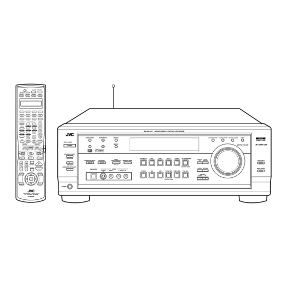
AUDIO/VIDEO CONTROL RECEIVER
RX-9010VBK
STANDBY
ON
MAIN ROOM
SUB ROOM
MAIN ROOM
SUB ROOM
TV/CATV/DBS
VCR1
ON/OFF
ON/OFF
POWER
POWER
DVD
DVD MULTI
PHONO
CD
VCR 1
VCR 2
TAPE/MD
CDR
TV/DBS
VIDEO
FM/AM
USB AUDIO
ANALOG/DIGITAL
L—BALANCE—R
EFFECT
INPUT
1
2
3
SOUND
CENTER
SUBWFR
ROOM SIZE
4
5
6
LEVEL+
REAR·L
REAR·R
LIVENESS
7
8
9
LEVEL–
DIGITAL EQ
CENTER TONE
10
0
+
10
100 +
RETURN
FM MODE
TEST
SURROUND
DSP
BASS BOOST
ON/OFF
MODE
STANDBY
LINE DIRECT
MIDNIGHT MODE
POWER
CONTROL
SLEEP
DIMMER
TV
CATV/
DBS
/REW
PLAY
FF/
SPEAKERS ON/OFF
DOWN
TUNING
UP
1
REC
STOP
PAUSE
MAIN ROOM
SURROUND ON/OFF
2
TV/VIDEO
SUB ROOM
TV VOL
CHANNEL
VOLUME
SUBWOOFER OUT ON/OFF
MUTING
TEXT
MENU
DISPLAY
SET
DVD
EXIT
MENU
PHONES
RM-SRX9010J
REMOTE CONTROL
A/V CONTROL RECEIVER
RX-9010V
AUDIO/VIDEO CONTROL RECEIVER
FM/AM TUNING
FM/AM PRESET
FM MODE
MEMORY
D I G I T A L
D I G I T A L
S U R R O U N D
DVD MULTI
DVD
VCR 1
INPUT
DSP MODE
ANALOG/DIGITAL
MIDNIGHT MODE
INPUT ATT
USB AUDIO
VIDEO
S-VIDEO
VIDEO
L—AUDIO—R
PHONO
CD
CDR
INSTRUCTIONS
MAIN ROOM ON/OFF
SUB ROOM ON/OFF
SUB ROOM CONTROL
MASTER VOLUME
VCR 2
VIDEO
TV SOUND/DBS
DIGITAL
LEVEL
EQ
ADJUST
SOURCE NAME
EFFECT SETTING
TAPE / MD
USB AUDIO
FM / AM
CONTROL
DOWN
UP
SOURCE NAME
DIMMER
LINE DIRECT
BASS BOOST
D I G I T A L
For Customer Use:
Enter below the Model No. and Serial
No. which are located either on the rear,
bottom or side of the cabinet. Retain this
information for future reference.
Model No.
Serial No.
LVT0620-001A
[J]
Advertisement
Table of Contents

Related Manuals for JVC RX-9010VBK


Summary of Contents for JVC RX-9010VBK
- Page 1 AUDIO/VIDEO CONTROL RECEIVER RX-9010VBK STANDBY MAIN ROOM SUB ROOM MAIN ROOM SUB ROOM TV/CATV/DBS VCR1 ON/OFF ON/OFF POWER POWER DVD MULTI PHONO VCR 1 VCR 2 TAPE/MD TV/DBS VIDEO FM/AM USB AUDIO ANALOG/DIGITAL L—BALANCE—R EFFECT INPUT SOUND CENTER SUBWFR ROOM SIZE LEVEL+ REAR·L...
- Page 2 Pour l’appareil principal: Déclaration de conformité Numéro de modèle: Nom de marque: Personne responsable: US JVC CORP. Adresse: Numéro de téléphone: (973) 315-5000 Cet ensemble se conforme à la partie 15 des règles de la FCC (Federal Communications Commission), Le fonctionnement est sujet aux deux conditions suivantes: (1) Cet appareil ne peut pas causer d’interférences nuisibles, et (2)
- Page 3 Veiller également à ce que l’air circule le mieux possible comme illustré. Spacing 15 cm or more Dégagement de 15 cm ou plus RX-9010VBK Front Avant Stand height 15 cm or more Hauteur du socle: 15 cm ou plus Floor...
-
Page 4: Table Of Contents
7 Searching for a Disc (Only for the CD player) ... 59 7 Entering the Disc Information ... 60 AV COMPU LINK Remote Control System ... 62 Operating JVC’s Audio/Video Components ... 65 Operating Audio Components ... 65 Operating Video Components ... 67 Operating Other Manufacturers’... -
Page 5: Introduction
Introduction We would like to thank you for purchasing one of our JVC products. Before operating this unit, read this manual carefully and thoroughly to obtain the best possible performance from your unit, and retain this manual for future reference. -
Page 6: Parts Identification
Parts Identification Refer to the pages in parentheses for details. Front Panel 3 4 5 FM/AM TUNING FM/AM PRESET FM MODE FM MODE STANDBY MEMORY POWER D I G I T A L D I G I T A L S U R R O U N D SPEAKERS ON/OFF MAIN ROOM... - Page 7 Remote Control STANDBY MAIN ROOM SUB ROOM MAIN ROOM SUB ROOM TV/CATV/DBS VCR1 ON/OFF ON/OFF POWER POWER MAIN ROOM SUB ROOM DVD MULTI PHONO TAPE/MD VCR 1 VCR 2 USB AUDIO TV/DBS VIDEO FM/AM ANALOG/DIGITAL L—BALANCE—R EFFECT INPUT CENTER SUBWFR ROOM SIZE SOUND LEVEL +...
-
Page 8: Getting Started
Getting Started This section explains how to connect audio/video components and speakers to the receiver, and how to connect the power supply. Before Installation General • Be sure your hands are dry. • Turn the power off to all components. •... -
Page 9: Connecting The Speakers
AM Antenna Connections Snap the tabs on the loop into the ANTENNA slots of the base to assemble the AM loop. FM 75 COAXIAL LOOP AM Loop Antenna Outdoor single vinyl-covered wire (not supplied) Turn the loop until you have the best reception. Notes: •... -
Page 10: Connecting Audio/Video Components
Connecting the rear and center speakers Connect rear speakers to the REAR SPEAKERS terminals and a center speaker to the CENTER SPEAKER terminals. Center speaker CENTER REAR SPEAKERS SPEAKER Right rear speaker – RIGHT LEFT CAUTION : SPEAKER IMPEDANCE Connecting the subwoofer speaker You can enhance the bass by connecting a subwoofer. - Page 11 Cassette deck or MD recorder Cassette deck To audio input AUDIO RIGHT LEFT REAR PHONO (REC) TAPE (PLAY) To audio input MD recorder Note: You can connect either a cassette deck or an MD recorder to the TAPE/MD jacks. When connecting an MD recorder to the TAPE/MD jacks, change the source name, which will be shown on the display when selected as the source, to “MD.”...
- Page 12 TV and/or DBS tuner When connecting the TV to the AUDIO jacks (TV SOUND/DBS), DO NOT connect the TV’s video output to these video input jacks. VIDEO AUDIO VIDEO S-VIDEO RIGHT LEFT FRONT TV SOUND (REC) VCR1 (PLAY) (REC) VCR2 (PLAY) MONITOR Connect the TV to the MONITOR OUT jack to...
-
Page 13: Digital Connections
Digital Connections This receiver is equipped with four DIGITAL IN terminals — one digital coaxial terminal and three digital optical terminals — and one DIGITAL OUT terminal. IMPORTANT: • When connecting the DVD player, digital TV broadcast tuner or DBS tuner using the digital terminals, you also need to connect it to the video terminal on the rear. -
Page 14: Usb Connection
USB Connection This receiver is equipped with a USB terminal on the front panel. You can connect your PC to this terminal and enjoy sound reproduced through your PC. When you connect your PC for the first time, follow the procedure below. -
Page 15: Setting Up The Rf Rod Antenna
Setting Up the RF Rod Antenna The remote control supplied for this receiver can transmit RF (Radio Frequency) signal. The RF rod antenna can receive the RF signals emitted from the remote control. So, with the RF rod antenna connected, you can operate the receiver at a distance of up to 50 feet (15 m) using the remote control. -
Page 16: Connecting The Power Cord
Connecting the Power Cord Before plugging the receiver into an AC outlet, make sure that all connections have been made. Plug the power cord into an AC outlet. Keep the power cord away from the connecting cables and the antenna. The power cord may cause noise or screen interference. We recommend that you use a coaxial cable to connect the antenna, since it is well-shielded against interference. -
Page 17: Multi-Room Operations
Multi-room Operations Before operating this receiver any further, be familiar with this Multi-room function. This function enables you to listen to different sources in two different places (we call these two places “main room” and “sub-room”) by using this receiver only. This section explains only required speaker connections, the concept, and basic operations of the Multi-room function. -
Page 18: Basic Operating Procedure For Main Room
Basic Operating Procedure for Main Room On the front panel: 1. Press POWER. The STANDBY lamp on the front panel goes off, and the MAIN ROOM indicator lights on the display. • For more details, “Turning the Power On and Off (Standby)” on page 17. -
Page 19: Basic Operating Procedure For Sub-Room
Basic Operating Procedure for Sub-Room The sources and functions available for the sub-room operations are limited. For more details on the sub-room operations, see “Sub-Room Operations” on pages 23 to 26. On the front panel: 1. Press POWER. The STANDBY lamp on the front panel goes off, and the MAIN ROOM indicator lights on the display. -
Page 20: Main Room Basic Operations
Main Room Basic Operations This section explains only the operations commonly used when you play any sound source in the main room. See pages 23 for the sub-room operations. You can use "On-screen Menu" for most of the main room operations. For details, see page 50. IMPORTANT: Check to see if the proper indicator(s) and information appear on the display on the front panel before/while using the buttons and controls. -
Page 21: Canceling The Main Room Operations
Canceling the Main Room Operations To stop the main room operations and sounds from the main room speakers, press MAIN ROOM ON/OFF. MAIN ROOM MAIN ROOM ON /OFF ON/OFF On the front panel From the remote control The MAIN ROOM indicator on the display goes off, and the currently selected front speaker indicators also goes off (no sound will be heard in the main room). -
Page 22: Adjusting The Main Room Volume
From the remote control: DVD MULTI PHONO TAPE/MD VCR 1 VCR 2 TV/DBS VIDEO FM/AM USB AUDIO Note: Once you have selected a video source, pictures of the selected source are sent to the TV until you select another video source. Speaker and signal indicators on the display By checking the following indicators, you can easily confirm which speakers you are activating and which signals are coming into this... -
Page 23: Adjusting The Equalization Patterns
On the front panel ONLY: When you have connected two pairs of the front speakers and set them to the main room, you can select which to use in the main room. To use the speakers connected to the FRONT 1 SPEAKERS terminals, press SPEAKERS ON/OFF 1 so that SPEAKERS 1 indicator lights up on the display. -
Page 24: Listening At Night - Midnight Mode
Listening at Night — Midnight Mode Using the midnight mode, you can enjoy a powerful sound at night even at a low volume level. • You can do this setting for each source. Press MIDNIGHT MODE. MIDNIGHT MODE MIDNIGHT MODE On the front panel From the remote control •... -
Page 25: Selecting The Line Direct Function
Selecting the Line Direct Function You can enjoy the sound closer to original source by skipping the sound adjustments such as Digital Equalization and Midnight Mode. Only the volume level and Bass Boost are adjustable when the Line Direct function is turned on. •... -
Page 26: Sub-Room Operations
Sub-Room Operations This section explains only the operations used when you play any sound source in the sub-room. See pages 17 for the main room operations. IMPORTANT: Check to see if the proper indicator(s) and information appear on the display on the front panel before/while using the buttons and controls. For the sub-room operations: •... -
Page 27: Canceling The Sub-Room Operations
From the remote control: 1. Set MAIN ROOM/SUB ROOM selector to “SUB ROOM.” MAIN ROOM SUB ROOM Now the buttons on the remote control work for the sub-room operations. 2. Press AUDIO POWER ON. STANDBY The STANDBY lamp on the front panel goes off, and the SUB ROOM indicator lights up on the display (and the SPEAKERS SUB ROOM indicator also lights up on the display if it has been activated). -
Page 28: Selecting The Sub-Room Source To Play
Selecting the Sub-room Source to Play Press one of the source selecting buttons. The lamp on the front panel button for selected source lights up. • The selected source name also appears on the display. • When the source name of TV SOUND/DBS is assigned to “TV SOUND,”... -
Page 29: Activating The Sub-Room Front Speakers
LINK remote control system or the AV COMPU LINK remote control system, see pages 55 to 64. – If they are one of the JVC products, but not equipped with the above remote control systems, or if they are the products of the other manufacturers, see pages 65 to 71. -
Page 30: Basic Settings
Basic Settings Some of the following settings are required after connecting and positioning your speakers, while others will make operations easier. • You can use “On-screen Menu” for most of the main room operations. For details, see page 50. The following operations are only possible while the receiver is ready for the main room operations. IMPORTANT: Check to see if the proper indicator(s) and information appear on the display on the front panel before/while using the buttons and controls. -
Page 31: Setting The Subwoofer Information
From the remote control: 1. Press SOUND. The 10 keys are activated for sound adjustments. 2. Press BALANCE R or BALANCE L to adjust the balance. • Pressing BALANCE R decreases the left channel output (from R –21 to CENTER, from CENTER to L –21). -
Page 32: Setting The Speakers For A Surround Field
Setting the Speakers for a Surround Field To obtain the best possible surround sound of the Surround and DSP modes, you have to register the information about the speakers arrangement after all connections are completed. • This function is applied only to the main room sources. Before you start, remember... -
Page 33: Digital Input (Digital In) Terminal Setting
Center speaker Front speaker Front speaker 2.1 m Rear speakers EX. In this case, set the center delay time to “1 ms” and the rear delay time to “2 ms.” Crossover Frequency Setting Small speakers cannot reproduce the bass sound very well. So, if you have used a small speaker for any of the front, center, and rear channels, this receiver automatically reallocate the bass elements, originally assigned to the channel for which you have connected the... -
Page 34: Selecting The Analog Or Digital Input Mode
To set the DIGITAL 2/3/4 terminals: 1. Press SETTING until DIGITAL 2/3/4 terminals setting appears on the display. The display changes to show the current settings for the DIGITAL 2/3/4 terminals. DIGITAL 2 terminal setting DIGITAL 3 terminal setting DIGITAL 4 terminal setting 2. -
Page 35: Selecting The Video Input Terminal
When playing a software encoded with the Dolby Digital or DTS Digital Surround, the following symptoms may occur: • Sound does not come out at the beginning of playback. • Noise comes out while using the searching for or skipping chapters or tracks. -
Page 36: Changing The Source Name
Changing the Source Name When you have connected an MD recorder to the TAPE/MD jacks or the DBS tuner to the TV SOUND/DBS jacks on the rear panel, change the source name which will be shown on the display when you select the MD recorder or DBS tuner as the source. -
Page 37: Basic Setting And Adjustment - Auto Memory
Basic Setting and Adjustment — Auto Memory Without any setting required, this receiver stores different sound settings for each different playing source automatically whenever you do the following: • Turning on the power (see page 17) • Changing the source to play (see page 18) •... -
Page 38: Receiving Radio Broadcasts
Receiving Radio Broadcasts You can browse through all the stations or use the preset function to go immediately to a particular station. • You can use “On-screen Menu” for most of the main room operations. For details, see page 50. Indicates the functions YOU CAN ALSO USE when the receiver is ready for the sub-room operations. -
Page 39: Selecting The Fm Reception Mode
4. Press MEMORY again while the selected channel number is flashing on the display. The selected channel number stops flashing. The station is assigned to the selected channel number. AUTO MUTING TUNED STEREO ANALOG SPEAKERS 5. Repeat steps 1 to 4 until you store all the stations you want. -
Page 40: Creating A Surround Field In The Main Room
Creating a Surround Field in the Main Room The built-in Surround Processor provides Surround mode and four types of the DSP (Digital Signal Processor) mode — DAP (Digital Acoustic Processor) mode, 5 CH/4 CH Stereo mode, 3D-PHONIC mode and HEADPHONE DSP mode. With this receiver, you can use a Surround mode and a DSP mode at the same time. -
Page 41: Reproducing The Sound Field
The 3D-PHONIC mode is the result of research on sound localization technology carried out at JVC for many years. This mode can be used when the front speakers are connected to this receiver (without respect to the rear/center speaker connection). -
Page 42: Available Dsp Modes According To The Speaker Arrangement
Available DSP Modes According to the Speaker Arrangement Available DSP modes will vary depending on how many speakers are used with this receiver. Make sure that you have set the speaker information correctly (see page 29). Speaker arrangements Front Front speaker speaker Center... -
Page 43: Adjusting The Surround Modes
Adjusting the Surround Modes Once you have adjusted the Surround modes, the adjustment is memorized for each source. You can also use a Surround mode with a DAP mode (see page 43). IMPORTANT: Check to see if the proper indicator(s) and information appear on the display on the front panel before/while using the buttons and controls. -
Page 44: Adjusting The Dap Modes
9. Press CENTER TONE to select the center tone level you want. The center tone adjustment affects the mid- frequency range, which the human voice is mostly made up of. • Each time you press the button, the display changes to show the following: CTR TONE 2 CTR TONE 1... - Page 45 Before you start, remember... • Make sure that you have set the speaker information correctly (see page 29). • When the SUB ROOM and SPEAKERS SUB ROOM indicators are lit on the display, you can only use 3D-PHONIC modes for the main room source.
-
Page 46: Adjusting The Surround Modes With The Dap Modes
From the remote control: 1. Press DSP MODE repeatedly until the DAP mode you want to adjust — THEATER 1, THEATER 2, HALL 1, HALL 2, LIVE CLUB, DANCE CLUB, or PAVILION — appears on the display. The DSP MODE lamp on the front panel button lights up, and the DSP indicator also lights up on the display. - Page 47 Before you start, remember... • Make sure that you have set the speaker information correctly (see page 29). • This function does not work when you activate the sub-room. • There is a time limit in doing the following steps. If the setting is canceled before you finish, start from step 4 again.
- Page 48 13.Press LIVENESS to adjust the liveness. • Each time you press the button, the display changes to show the following: LIVENESS 1 LIVENESS 2 LIVENESS 5 LIVENESS 4 As the number increases, the attenuation level of reflections over time decreases so that acoustics change from “Dead” to “Live.” (Normally set it to “LIVENESS 3.”) On the front panel: You can also use the buttons on the front panel to adjust the sound...
-
Page 49: Adjusting The 5 Ch/4 Ch Stereo Mode
8. Adjust the liveness. 1) Press EFFECT repeatedly until “LIVENESS” appears on the display. The display changes to show the current setting. 2) Press CONTROL UP 5/DOWN ∞ to select the liveness level you want. • Each time you press the button, the display changes to show the following: LIVENESS 1 LIVENESS 2... -
Page 50: Adjusting The 3D-Phonic Modes
From the remote control: 1. Press DSP MODE repeatedly until “5CH STEREO*” appears on the display. The DSP MODE lamp on the front panel button lights up, and the DSP indicator also lights up on the display. * “4CH STEREO” appears on the display when you have set “CTR SPK”... - Page 51 On the front panel: 1. Press DSP MODE repeatedly until “3D ACTION” or “3D DIGITAL” appears on the display. The DSP MODE lamp on the front panel button lights up, and the 3D-PHONIC and DSP indicators also light up on the display. 2.
-
Page 52: Using The Dvd Multi Playback Mode
Using the DVD MULTI Playback Mode This receiver provides the DVD MULTI playback mode for reproducing the analog discrete output mode of the DVD player. Before playing back a DVD, refer also to the manual supplied for the DVD player. •... -
Page 53: Using The On-Screen Menus
Using the On-Screen Menus You use the black-and-white color Menus on the TV screen to control the receiver. To use this function, you need to connect the TV to the MONITOR OUT jack on the rear panel (see page 9), and set the TV’s input mode to the proper position to which the receiver is connected. -
Page 54: Adjusting The Equalization Patterns
Adjusting the Equalization Patterns (Also see page 20) 1. Press MENU. The MENU appears on the TV. • Pressing one of the % / fi / @ / # buttons also displays the MENU. 2. Press % / fi to move to “SOUND CONTROL,”... -
Page 55: Adjusting The Dvd Multi Playback Mode
7. Press % / fi to move SOUND CONTROL to “EFFECT ADJUST,” then press @ / #. MIDNIGHT MODE: NORMAL The EFFECT LEVEL menu INPUT ATT LINE DIRECT: OFF appears. BASS BOOST : OFF SUBWOOFER 8. Press % / fi to move EFFECT ADJUST to the item you want to adjust, then press... -
Page 56: Selecting The Line Direct Function
Selecting the Line Direct Function (Also see page 22) 1. Press MENU. The MENU appears on the TV. • Pressing one of the % / fi / @ / # buttons also displays the MENU. 2. Press % / fi to move to “SOUND CONTROL,”... -
Page 57: Storing The Preset Stations
Storing the Preset Stations (Also see page 35) 1. Press MENU. The MENU appears on the TV. • Pressing one of the % / fi / @ / # buttons also displays the MENU. 2. Press % / fi to move to “TUNER CONTROL,”... -
Page 58: Compu Link Remote Control System
COMPU LINK Remote Control System The COMPU LINK remote control system allows you to operate JVC audio components through this receiver. To use this remote control system, you need to connect JVC audio components through the COMPU LINK (SYNCHRO) jacks (see below) in addition to the connections using cables with RCA pin plugs (see pages 7 and 8). - Page 59 Automatic Power On/Off (Standby): only possible with the COMPU LINK-3 and COMPU LINK--4 connection Automatic Power On: • When you turn on the receiver by pressing POWER on the front panel or AUDIO POWER ON on the remote control (with MAIN ROOM/SUB ROOM selector set to “MAIN ROOM”): When you turn on the main room sound by pressing MAIN ROOM ON/OFF while the receiver is turned on:...
-
Page 60: Text Compu Link Remote Control System
TEXT COMPU LINK Remote Control System The TEXT COMPU LINK remote control system has been developed to deal with the disc information recorded in the CD Text * and MDs. Using this information in the discs, you can operate the CD player or MD recorder equipped with the TEXT COMPU LINK remote control system through the receiver. -
Page 61: Showing The Disc Information On The Tv Screen
OPERATIONS: To use this remote control system, you need to connect the TV to the MONITOR OUT jack on the rear panel (see page 9), and set the TV’s input mode to the proper position to which the receiver is connected. -
Page 62: Searching For A Disc (Only For The Cd Player)
Searching for a Disc (Only for the CD player) Search for a disc by its performer: 1. Press TEXT DISPLAY while “CD” is selected as the source. The Disc Information screen appears on the TV. 2. Press % / fi to move to “SEARCH,”... -
Page 63: Entering The Disc Information
Search for a disc by its genre: 1. Press TEXT DISPLAY while “CD” is selected as the source. The Disc Information screen appears on the TV. 2. Press % / fi to move to “SEARCH,” then press SET. The DISC SEARCH screen appears. 3. - Page 64 4. Repeat step 3 until you finish putting a performer name (up to 32 characters). To insert a space, press % / fi / @ / # to move , then press SET. To correct an incorrect character: 1) Press % / fi / @ / # to move to + or =, then press SET until the incorrect character is selected.
-
Page 65: Av Compu Link Remote Control System
This receiver is equipped with the AV COMPU LINK-III. The AV COMPU LINK remote control system allows you to operate JVC video components (TV, VCR, and DVD player) through the receiver. To use this remote control system, you need to connect the video components you want to operate, following the procedure below. - Page 66 • The IR signal transmitter can send signals at a distance of 10 feet (3 m). DVD player IR signal transmitter RX-9010VBK You can control the connected video components using this remote control: Aim the remote control at the remote sensors on the target video component(s) or on the receiver directly.
- Page 67 One-Touch DVD Play Simply by starting playback on the DVD player, you can enjoy the DVD playback without setting other switches manually. When you press PLAY on the remote control supplied with this receiver for operating the DVD player, the receiver automatically turns on and changes the main room source or sub-room source (depending on MAIN ROOM/SUB ROOM selector setting on the remote control) to the appropriate input —...
-
Page 68: Operating Jvc's Audio/Video Components
Operating JVC’s Audio/Video Components You can operate JVC’s audio and video components with this receiver’s remote control, since control signals for JVC components are preset in the remote control. Operating Audio Components IMPORTANT: To operate JVC’s audio components using this remote control: •... - Page 69 CD player-changer After selecting CDDSC by pressing CONTROL repeatedly, you can perform the following operations on a CD player-changer: PLAY: Starts playing. Returns to the beginning of the current (or previous) track. ¢: Skips to the beginning of the next track. STOP: Stops playing.
-
Page 70: Operating Video Components
COMPU LINK jacks (see page 62) in addition to the connections using cables with RCA pin plugs (see pages 8 and 9). • Some JVC VCRs can accept two types of the control signals — remote codes “A” and “B.” Before using this remote control, make sure that the remote control code of the VCR connected to the VCR 1 terminals is set to code “A.”... -
Page 71: Operating Other Manufacturers' Equipment
Operating Other Manufacturers’ Equipment This remote control supplied with the receiver can transmit control signals for other manufacturers’ VCRs, TVs, CATV converters, DBS tuners, DVD players ,and CD players. By changing the transmittable signals from preset ones to the other manufacturers’, you can operate the other manufacturer’s components using this remote control. When operating the other manufacturers’... - Page 72 To change the transmittable signals for operating a CATV converter and DBS tuner 1. Set TV/CATV/DBS selector to “CATV/DBS.” 2. Press and hold TV/CATV/DBS POWER. 3. Press TV/DBS. 4. Enter manufacturer’s code using buttons 1–9, and 0. See pages 70 and 71 to find the code. 5.
- Page 73 METS MITSUBISHI PANASONIC PHILIPS QUELLE RCA/PROSC SAMSUNG SANYO SHARP SONY TOSHIBA ZENITH *This figure is set to the remote control as the initial JVC cord. Manufactures' codes for DBS tuner Manufacturer AMSTRAD BLAUPUNKT ECHOSTAR GOLDSTAR GRUNDIG HIRSHMANN INSTRUMENT ITT/NOKIA KATHREIN...
- Page 74 SHARP 37, 50 SONY 52, 53, 54 TOSHIBA 43, 44 ZENITH 56, 57 *This figure is set to the remote control as the initial JVC cord. Manufactures' codes for DVD player Manufacturer 00*, 02 DENON PANASONIC PHILIPS PIONEER 04, 05, 06...
-
Page 75: Troubleshooting
Troubleshooting Use this chart to help you solve daily operational problems. If there is any problem you cannot solve, contact your JVC service center. PROBLEM The display does not light up. The buttons and controls on the front panel do not work. - Page 76 PROBLEM Continuous hiss or buzzing during FM reception. Occasional cracking noise during FM reception. Howling during record playing. No sound from PC connected with a USB cable. Noise while reproducing PC sound connected with a USB cable. Sound from PC connected with a USB cable stops intermittently.
-
Page 77: Specifications
Specifications Amplifier Output Power At Stereo operation: 120 W per channel, min. RMS, Front channels: driven into 8 , 20 Hz to 20 kHz with no more than 0.02% total harmonic distortion. 120 W per channel, min. RMS, driven into 4 , 20 Hz to 20 kHz with no more than 0.08% total harmonic distortion. - Page 78 Sophisticated electronic products may require occasional service. Just as quality is a keyword in the engineering and production of the wide array of JVC products, service is the key to maintaining the high level of performance for which JVC is world famous. The JVC service and engineering organization stands behind our products.
- Page 79 WHAT WE WILL DO: If this product is found to be defective, JVC will repair or replace defective parts at no charge to the original owner. Such repair and replacement services shall be rendered by JVC during normal business hours at JVC authorized service centers.
- Page 80 VICTOR COMPANY OF JAPAN, LIMITED 0201NHMMDWJEIN...