Table of Contents
Advertisement
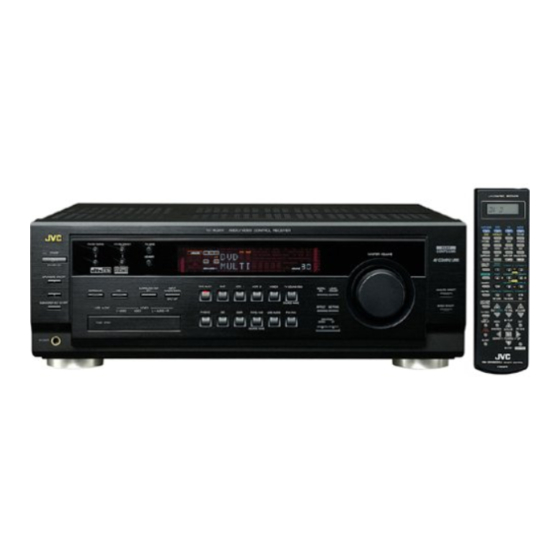
AUDIO/VIDEO CONTROL RECEIVER
RX-8020VBK
A/V CONTROL RECEIVER
CATV/DBS
VCR1
TV
AUDIO
DVD
DVD MULTI
CD
FM/AM
TV/DBS
VIDEO
CDR
PHONO
VCR1
VCR 2
TAPE/MD
USB
SURROUND
DSP
SURR/DSP ANALOG/DIGITAL
OFF
INPUT
ANALOG
BASS
∗
∗
DIRECT
BOOST
FRONT•L
FRONT•R
1
2
3
MENU
∗
∗
SOUND
TEST
CENTER
SUBWFR
4
5
6
STANDBY
ENTER
∗
∗
DIMMER
SURR•L
SURR•R
7/P
8
9
STANDBY/ON
∗
∗
∗
MUTING
DIGITAL EQ
SBACK•L
SBACK•R
10
0
+10
100 +
RETURN
FM MODE
SPEAKERS ON/OFF
CATV/DBS
1
CONTROL
+
+
+
∗
CH/
LEVEL TV VOL
VOLUME
2
TV/VIDEO
−
−
−
TEXT
SUBWOOFER OUT ON/OFF
PLAY
DISPLAY
MENU
EXIT
REC
/REW
FF/
PAUSE
PAUSE
SET
DOWN – TUNING – UP
SLEEP
STOP
CONTROL
PHONES
RM-SRX8020J
REMOTE CONTROL
RX-8020V
AUDIO/VIDEO CONTROL RECEIVER
FM/AM TUNING
FM/AM PRESET
FM MODE
MEMORY
DVD MULTI
DVD
VCR 1
SURROUND/DSP
INPUT
SURROUND
DSP
OFF
ANALOG/DIGITAL
INPUT ATT
VIDEO
USB AUDIO
S-VIDEO
VIDEO
L—AUDIO—R
PHONO
CD
CDR
PUSH OPEN
INSTRUCTIONS
MASTER VOLUME
VCR 2
VIDEO
TV SOUND/DBS
DIGITAL
LEVEL
EQ
ADJUST
SOUCE NAME
EFFECT SETTING
TAPE/MD
USB AUDIO
FM/AM
CONTROL
DOWN
UP
SOURCE NAME
ANALOG DIRECT
BASS BOOST
For Customer Use:
Enter below the Model No. and Serial
No. which are located either on the rear,
bottom or side of the cabinet. Retain this
information for future reference.
Model No.
Serial No.
LVT0870-001A
[J]
Advertisement
Chapters
Table of Contents
Troubleshooting

Related Manuals for JVC RX-8020VBK


Summary of Contents for JVC RX-8020VBK
- Page 1 AUDIO/VIDEO CONTROL RECEIVER RX-8020VBK A/V CONTROL RECEIVER CATV/DBS VCR1 AUDIO DVD MULTI FM/AM TV/DBS VIDEO PHONO VCR1 VCR 2 TAPE/MD SURROUND SURR/DSP ANALOG/DIGITAL INPUT ANALOG BASS ∗ ∗ DIRECT BOOST FRONT•L FRONT•R MENU FM/AM TUNING FM/AM PRESET ∗ ∗ SOUND...
- Page 2 Déclaration de conformité Numéro de modèle: Nom de marque: Personne responsable: US JVC CORP. Adresse: Numéro de téléphone: (973) 315-5000 Cet ensemble se conforme à la partie 15 des règles de la FCC (Federal Communications Commission), Le fonctionnement est sujet aux deux conditions suivantes: (1) Cet appareil ne peut pas causer d’interférences nuisibles, et (2)
- Page 3 Veiller également à ce que l’air circule le mieux possible comme illustré. Spacing 15 cm or more Dégagement de 15 cm ou plus RX-8020VBK Front Avant Stand height 15 cm or more Hauteur du socle: 15 cm ou plus radio...
-
Page 4: Table Of Contents
7 Searching for a Disc (Only for the CD player) ... 46 7 Entering the Disc Information ... 47 AV COMPU LINK Remote Control System ... 49 Operating JVC’s Audio/Video Components ... 51 Operating Audio Components ... 51 Operating Video Components ... 53 Operating Other Manufacturers’... -
Page 5: Introduction
Introduction We would like to thank you for purchasing one of our JVC products. Before operating this unit, read this manual carefully and thoroughly to obtain the best possible performance from your unit, and retain this manual for future reference. -
Page 6: Parts Identification
Parts Identification Become familiar with the buttons and controls on the receiver before use. Refer to the pages in parentheses for details. Front Panel 3 4 5 FM/AM TUNING FM/AM PRESET FM MODE STANDBY MEMORY STANDBY/ON SPEAKERS ON/OFF SURROUND/DSP SURROUND SUBWOOFER OUT ON/OFF USB AUDIO VIDEO... -
Page 7: Remote Control
Remote Control A/V CONTROL RECEIVER CATV/DBS VCR1 AUDIO DVD MULTI FM/AM TV/DBS VIDEO PHONO VCR1 VCR2 TAPE/MD SURROUND SURR/DSP ANALOG/DIGITAL INPUT ANALOG BASS ∗ ∗ DIRECT BOOST FRONT•L FRONT•R MENU ∗ ∗ SOUND TEST CENTER SUBWFR ENTER ∗ ∗ DIMMER SURR•L SURR•R ∗... -
Page 8: Getting Started
Getting Started This section explains how to connect audio/video components and speakers to the receiver, and how to connect the power supply. Before Installation General Precautions • Be sure your hands are dry. • Turn the power off to all components. •... -
Page 9: Connecting The Speakers
AM Antenna Connections ANTENNA Turn the loop until you have FM 75 the best reception. COAXIAL AM Loop Antenna LOOP (supplied) Snap the tabs on the loop into the slots of the base to assemble the AM loop. Outdoor single vinyl-covered wire (not supplied) Notes: •... - Page 10 Basic connecting procedure Connecting the front, center and surround speakers Surround Front speakers 2 speakers Right / Left Center speaker CAUTION : SPEAKER IMPEDANCE RIGHT – – RIGHT LEFT CENTER SURROUND SPEAKERS SPEAKER Connecting the surround back speakers To fully enjoy Dolby Digital EX and DTS-ES Extended Surround (see pages 32 and 33), you need to connect the surround back speakers through a power amplifier connected to the PRE OUT SURR BACK jacks on the rear panel, using a cable with RCA pin...
-
Page 11: Connecting Audio/Video Components
Enhancing your audio system You can use this receiver as the pre-amplifier (control amplifier) when you connect power amplifiers to the PRE OUT jacks on the rear panel using cables with RCA pin plugs (not supplied). Connect the white plug to the audio left jack, and the red plug to the audio right jack. - Page 12 CD player CENTER WOOFER CD player To audio output Cassette deck or MD recorder Cassette deck To audio input CENTER RIGHT LEFT WOOFER To audio input MD recorder Note: You can connect either a cassette deck or an MD recorder to the TAPE/MD jacks.
- Page 13 Video component connections Use the cables with RCA pin plugs (not supplied). Connect the white plug to the audio left jack, the red plug to the audio right jack, and the yellow plug to the video jack. • If your video components have S-video (Y/C-separation) and/or component video (Y, P ) terminals, connect them using an S-video cable (not supplied) and/or component video cable (not...
- Page 14 TV and/or DBS tuner AUDIO RIGHT LEFT Å To audio output ı To composite video input Ç To S-video input Î To component video input AUDIO RIGHT LEFT DBS tuner Å To audio output ı To S-video output Ç To component video output Î...
- Page 15 DVD player • When you connect a DVD player with stereo output jacks: AUDIO RIGHT LEFT FRONT TV SOUND DVD player MONITOR Å To front left/right audio output ı To S-video output Ç To component video output Î To composite video output •...
-
Page 16: Digital Connections
Digital Connections This receiver is equipped with four DIGITAL IN terminals—one digital coaxial terminal and three digital optical terminals—and one DIGITAL OUT terminal. IMPORTANT: • When connecting a DVD player, digital TV broadcast tuner or DBS tuner using the digital terminals, you also need to connect it to the video jacks on the rear. -
Page 17: Usb Connection
USB Connection This receiver is equipped with a USB terminal on the front panel. You can connect your PC to this terminal and enjoy sound reproduced through your PC. When you connect your PC for the first time, follow the procedure below. -
Page 18: Connecting The Power Cord
Connecting the Power Cord Before plugging the receiver into an AC outlet, make sure that all connections have been made. Plug the power cord into an AC outlet. Keep the power cord away from the connecting cables and the antenna. The power cord may cause noise or screen interference. We recommend that you use a coaxial cable to connect the antenna, since it is well-shielded against interference. -
Page 19: Basic Operations
Basic Operations The following operations are commonly used when you play any sound sources. Before using the remote control How to confirm the remote control operation mode The display window on the remote control shows the following information when you press certain buttons on the remote control, so that you can confirm which operation you do. - Page 20 Changing the source name When you have connected an MD recorder to the TAPE/MD jacks or a DBS tuner to the TV SOUND/DBS jacks on the rear panel, change the source name which will be shown on the display. On the front panel ONLY: When changing the source name from “TAPE”...
-
Page 21: Adjusting The Volume
Adjusting the Volume On the front panel: To increase the volume, turn MASTER VOLUME clockwise. To decrease the volume, turn it counterclockwise. From the remote control: To increase the volume, press VOLUME +. To decrease the volume, press VOLUME –. CAUTION: Always set the volume to the minimum before starting any sources. -
Page 22: Selecting The Analog Or Digital Input Mode
Selecting the Analog or Digital Input Mode When you have connected digital source components using the digital terminals (see page 13), you need to change the input mode for these components to the appropriate digital input mode correctly—DGTL AUTO, DGTL DTS, or DGTL D.D. Before you start, remember... -
Page 23: Muting The Sound
Muting the Sound From the remote control ONLY: Press MUTING to mute the sound through all speakers and headphones connected. “MUTING” appears on the display and the volume turns off (the volume level indicator goes off). ANALOG SPEAKERS 1 Ex.: When the source is “DVD.” To restore the sound, press MUTING again. -
Page 24: Basic Settings
Basic Settings Some of the following settings are required after connecting and positioning your speakers while others will make operations easier. • When performing the basic settings, it is recommended to use the remote control so that you can show the on-screen display on the TV. -
Page 25: Setting The Speakers
1 Setting the Speakers To obtain the best possible surround sound from the Surround and DSP modes, you have to register the setting about the speaker arrangement after all connections are completed. 7 Subwoofer setting—SUBWOOFER [On-screen display] Select whether you have connected a subwoofer or not. : Select this when a subwoofer is connected. -
Page 26: Selecting Channel Numbers To Reproduce Multi-Channel Digital Software
2 Selecting Channel Numbers to Reproduce Multi-channel Digital Software—EX/ES [On-screen display] You can select 5.1-channel reproduction or 6.1-channel reproduction when playing back multi-channel (more than 5.1-channel) digital software with setting the surround back speakers to “LARGE” or “SMALL” (see page 22). “AUTO” is initial setting. AUTO : Select this to reproduce signals originally recorded as marked on the software such as •... -
Page 27: Setting The Bass Sounds
4 Setting the Bass Sounds You can adjust subwoofer and bass sounds precisely according to your preference. 7 Crossover frequency—CROSSOVER [On-screen display] When you use a subwoofer, you can select the cutoff frequency for the small speakers used. Select one of the crossover frequency levels from “80Hz,” “100Hz,”... -
Page 28: Setting The Digital Input (Digital In) Terminals
6 Setting the Digital Input (DIGITAL IN) Terminals [On-screen display] When you use the digital input terminals, you have to register which components you have connected to the digital input terminals. 7 Digital coaxial terminal—DIGITAL 1 (DGTL COAX 1) Set the component connected to the digital coaxial terminal (DIGITAL IN 1)—DVD, MD**, CDR, TV (or DBS*) or CD. -
Page 29: Memorizing The Volume Level For Each Source
8 Memorizing the Volume Level for Each Source —ONE TOUCH OPR (ONE TOUCH) [On-screen display] This unit memorizes some settings separately for each source—One Touch Operation (see page 20). In addition, you can store the volume level for each source with the other memorized settings. -
Page 30: Receiving Radio Broadcasts
Receiving Radio Broadcasts You can browse through all the stations or use the preset function to go immediately to a particular station. Tuning into Stations Manually On the front panel: 1. Press FM/AM to select the band (FM or AM). The FM/AM lamp on the front panel button lights up. -
Page 31: Selecting The Fm Reception Mode
To tune in a preset station On the front panel: 1. Press FM/AM to select the band (FM or AM). The FM/AM lamp on the front panel button lights up. The last received station of the selected band is tuned in. •... -
Page 32: Operating The Tuner Using The On-Screen Display
Operating the Tuner Using the On-Screen Display You can also operate the tuner using the on-screen display. • The on-screen display will disappear if no operation is done for about 1 minute. 7 Operating the tuner 1. Press MENU. The MENU screen appears on the TV. -
Page 33: Setting Sound
Setting Sound You can select the following sound settings to your preference according to your listening conditions or sources. • Items shown in this section are the initial values when shipped from the factory. • The on-screen display will disappear if no operation is done for about 1 minute. Attenuating the Input Signal When the input level of the analog source is too high, the sounds will be distorted. -
Page 34: Reinforcing The Bass
Reinforcing the Bass You can boost the bass level. • Once you have made adjustment, it is memorized for each source. On the front panel: Press BASS BOOST to turn on Bass Boost function. The BASS BOOST lamp on the front panel button lights up. -
Page 35: Using Surround Modes And Dsp Modes
Using Surround Modes and DSP Modes This unit activates a variety of Surround modes and DSP (Digital Signal Processor) modes. To use Surround and DSP modes properly, speakers required for creating each Surround and DSP modes should be activated. I Surround Modes Reproducing Theater Ambience In a movie theater, many speakers are located on the walls to reproduce impressive multi-surround sounds, reaching you from all... -
Page 36: Dts Digital Surround
When using Surround mode, the sounds come out of all the connected and activated speakers. • If only the front speakers are connected, JVC’s original 3D- PHONIC processing (which has been developed to create the surround effect only through the front speakers) is used. -
Page 37: Dsp Modes
Reproduces the sound field of a small theater (where the seating capacity is about 300). When using DAP mode or JVC Theater Surround, the sounds come out of all the connected and activated speakers. • If only the front speakers are connected or the front and center speakers are connected, JVC’s original 3D-PHONIC... -
Page 38: Available Surround And Dsp Modes According To The Speaker Layouts
Available Surround and DSP Modes According to the Speaker Layouts Available Surround and DSP modes will vary depending on how many speakers are used with this receiver. Make sure that you have set the speaker setting correctly (see page 22). •... -
Page 39: Activating The Surround Modes
If Analog Direct is turned on when using analog input mode (see pages 19 and 30), currently selected Surround and/or DSP mode is canceled temporarily. Available Surround mode From the remote control JVC Theater All Channel Headphone modes Surround Stereo... -
Page 40: Using The Dvd Multi Playback Mode
Using the DVD MULTI Playback Mode This receiver provides the DVD MULTI playback mode for reproducing the analog discrete output mode of the DVD player. Before playing back a DVD, refer also to the manual supplied with the DVD player. When using DVD MULTI playback mode, connect the DVD player with its analog discrete output jacks (Å... -
Page 41: Adjusting Sound
Adjusting Sound You can adjust sound parameters to your preference after completing basic setting. • When performing the sound adjustments, it is recommended to use the TV screen so that you can show the on-screen display on the TV. • When using the buttons on the front panel or remote control without using the on-screen display, you can perform the same adjustments. -
Page 42: Adjusting The Equalization Patterns-Digital Eq
Adjusting the Equalization Patterns —DIGITAL EQ You can adjust the equalization patterns to your preference. • Once you have made adjustment, it is memorized for each source. Using the on-screen display (through the remote control]: 1. Show DIGITAL EQ (Equalization) menu (see page 38). -
Page 43: Adjusting The Speaker Output Levels-Level Adjust
Adjusting the Speaker Output Levels —LEVEL ADJUST You can adjust the speaker output levels. The test tone can be also output from each speaker except subwoofer to check the output level balance when using the Surround mode. • Once you have made adjustment, it is memorized for each source. •... - Page 44 From the remote control: Before you start, remember... There is a time limit in doing the following steps. If the setting is canceled before you finish, start from step 2 again. Adjustment is also possible without outputting the test tone. In this case, you can skip steps 2 and 6 below.
-
Page 45: Adjusting The Sound Parameters For The Surround And Dsp Modes-Effect Adjust
• Once you have made adjustment, it is memorized for each source. 7 Adjustable parameters You can adjust the following parameters: For Surround, DAP, JVC Theater Surround and All Channel Stereo modes (when the center speaker is connected) CENTER TONE : Adjust the center tone. -
Page 46: Compu Link Remote Control System
COMPU LINK Remote Control System The COMPU LINK remote control system allows you to operate JVC’s audio components through the remote sensor on the receiver. To use this remote control system, you need to connect JVC’s audio components through the COMPU LINK (SYNCHRO)-4 jacks (see below) in addition to the connections using cables with RCA pin plugs (see pages 8 and 9). -
Page 47: Text Compu Link Remote Control System
TEXT COMPU LINK Remote Control System The TEXT COMPU LINK remote control system has been developed to deal with the disc information recorded in the CD Text* and MDs. Using these information in the discs, you can operate a CD player or MD recorder equipped with the TEXT COMPU LINK remote control system through the receiver. -
Page 48: Showing The Disc Information On The Tv Screen
Operations: To use this remote control system, you need to connect the TV to the MONITOR OUT jack on the rear panel (see page 11), and set the TV’s input mode to the proper position to which the receiver is connected. -
Page 49: Searching For A Disc (Only For The Cd Player)
Searching for a Disc (Only for the CD player) Search for a disc by its performer: 1. Press TEXT DISPLAY while “CD” is selected as the source. The Disc Information screen appears on the TV. 2. Press 5 or ∞ to move to “SEARCH,”... -
Page 50: Entering The Disc Information
Search for a disc by its genre: 1. Press TEXT DISPLAY while “CD” is selected as the source. The Disc Information screen appears on the TV. 2. Press 5 or ∞ to move to “SEARCH,” then press SET. The DISC SEARCH screen appears. - Page 51 4. Repeat step 3 until you finish putting a performer name (up to 32 characters). To insert a space, press 5 / ∞ / 2 / 3 to move then press SET. To correct an incorrect character: 1) Press 5 / ∞ / 2 / 3 to move to + or =, then press SET until the incorrect character is selected.
-
Page 52: Av Compu Link Remote Control System
This receiver is equipped with the AV COMPU LINK-III, which adds a function to operate JVC’s video components through the video components terminals. To use this remote control system, you need to connect the video components you want to operate, following the diagrams below and the procedure on the next page. - Page 53 1. If you have already plugged your VCR 1 (VCR connected to the VCR 1 jacks), DVD player, TV and this receiver into the AC outlets, unplug their AC power cords first. 2. Connect your VCR 1, DVD player, TV and this receiver, using the cables with the monaural mini- plugs (not supplied).
-
Page 54: Operating Jvc's Audio/Video Components
Operating JVC’s Audio/Video Components You can operate JVC’s audio and video components with this receiver’s remote control, since control signals for JVC’s components are preset in the remote control. Operating Audio Components IMPORTANT: To operate JVC’s audio components using this remote control: •... - Page 55 CD changer After selecting “CDDSC” by pressing CONTROL repeatedly, you can perform the following operations on a CD changer: 3 PLAY :Start playing. :Return to the beginning of the current (or previous) track. ¢ :Skip to the beginning of the next track. 7 STOP :Stop playing or recording.
-
Page 56: Operating Video Components
VCR connected to the VCR 1 jacks is set to code “A.” – When another JVC’s VCR is connected to the VCR 2 or VIDEO terminals, set its remote control code to code “B.” (This remote control cannot emit the control signals of code “B.”) -
Page 57: Operating Other Manufacturers' Video Equipment
Operating Other Manufacturers’ Video Equipment This remote control supplied with the receiver can transmit control signals for other manufacturers’ TVs, CATV converters, DBS tuners, VCRs and DVD players. By changing the transmittable signals from preset ones to the other manufacturers’, you can operate the other manufacturers’... - Page 58 To change the transmittable signals for operating a CATV converter or DBS tuner 1. Press and hold CATV/DBS 2. Press CATV/DBS CONTROL. “CALL” appears on the remote control display window. 3 Enter a manufacturer’s code using buttons 1–9, and 0. See the following lists to find the code.
- Page 59 Manufacturer Codes , 26, 27, 28, 29, 58 AIWA 01, 02 BELL & HOWELL BLAUPUNKT 04, 05 06, 07 EMERSON 08, 10, 11, 12, 64, 65 FISHER 03, 14, 15, 16, 17 FUNAI 18, 19, 20 GOLDSTAR GOODMANS 13, 21 GRUNDIG 06, 22 HITACHI...
-
Page 60: Troubleshooting
Troubleshooting Use this chart to help you solve daily operational problems. If there is any problem you cannot solve, contact your JVC’s service center. PROBLEM The display does not light up. No sound from speakers. Sound from one speaker only. - Page 61 PROBLEM “OVERLOAD” starts flashing on the display. The STANDBY lamp lights up after turning on the power, and soon the receiver turns off again (into standby mode). Remote control does not work. Remote control does not work intendedly. POSSIBLE CAUSE Speakers are overloaded because of high volume.
-
Page 62: Specifications
Specifications Amplifier Output Power: Audio Audio Input Sensitivity/Impedance (1 kHz): Audio Input (DIGITAL IN)* : Audio Output Level: Recording Output Level: Digital output: Signal-to-Noise Ratio (’66 IHF/’78 IHF): Frequency Response (8 Ω): RIAA Phono Equalization: Bass boost: Video Video Input Sensitivity/Impedance: Composite video: S-video: Component video:... - Page 63 FM tuner (IHF) Tuning Range: Usable Sensitivity: 50 dB Quieting Sensitivity: Signal-to-Noise Ratio (IHF-A weighted): Total Harmonic Distortion: Stereo Separation at REC OUT: Alternate Channel Selectivity: Frequency Response: AM tuner Tuning Range: Usable Sensitivity: Signal-to-Noise Ratio: General Power Requirements: Power Consumption: Dimensions (W x H x D): Mass: 87.5 MHz to 108.0 MHz...
- Page 64 To prevent electrical shock,do not open the cabinet.There are no user serviceable parts inside.Please refer to qualified service personnel for repairs. Accessories To purchase accessories for your JVC product,please call toll free:1 (800)882-2345 or on the web at www.JVC.com BT-51002-5 (0301) ®...
- Page 65 If service is not available locally, box the product carefully, preferably in the original carton, and ship, insured, with a copy of your bill of sale plus a letter of explanation of the problem to the nearest JVC Factory Service Center, the name and location of which will be given to you by the toll-free number.
- Page 66 VICTOR COMPANY OF JAPAN, LIMITED 0302NHMMDWJEIN...
- Page 67 AUDIO/VIDEO CONTROL RECEIVER RECEPTEUR DE COMMANDE AUDIO/VIDEO RX-8020VBK A/V CONTROL RECEIVER CATV/DBS VCR1 AUDIO DVD MULTI FM/AM TV/DBS VIDEO PHONO VCR1 VCR 2 TAPE/MD SURROUND SURR/DSP ANALOG/DIGITAL INPUT ANALOG BASS ∗ ∗ DIRECT BOOST FRONT•L FRONT•R MENU FM/AM TUNING FM/AM PRESET ∗...
- Page 68 Déclaration de conformité Numéro de modèle: Nom de marque: Personne responsable: US JVC CORP. Adresse: Numéro de téléphone: (973) 315-5000 Cet ensemble se conforme à la partie 15 des règles de la FCC (Federal Communications Commission), Le fonctionnement est sujet aux deux conditions suivantes: (1) Cet appareil ne peut pas causer d’interférences nuisibles, et (2)
- Page 69 Veiller également à ce que l’air circule le mieux possible comme illustré. Spacing 15 cm or more Dégagement de 15 cm ou plus RX-8020VBK Front Avant Stand height 15 cm or more Hauteur du socle: 15 cm ou plus radio...
- Page 70 7 Searching for a Disc (Only for the CD player) ... 46 7 Entering the Disc Information ... 47 AV COMPU LINK Remote Control System ... 49 Operating JVC’s Audio/Video Components ... 51 Operating Audio Components ... 51 Operating Video Components ... 53 Operating Other Manufacturers’...
-
Page 71: Introduction
Introduction We would like to thank you for purchasing one of our JVC products. Before operating this unit, read this manual carefully and thoroughly to obtain the best possible performance from your unit, and retain this manual for future reference. -
Page 72: Parts Identification
Parts Identification Become familiar with the buttons and controls on the receiver before use. Refer to the pages in parentheses for details. Front Panel 3 4 5 FM/AM TUNING FM/AM PRESET FM MODE STANDBY MEMORY STANDBY/ON SPEAKERS ON/OFF SURROUND/DSP SURROUND SUBWOOFER OUT ON/OFF USB AUDIO VIDEO... - Page 73 Remote Control A/V CONTROL RECEIVER CATV/DBS VCR1 AUDIO DVD MULTI FM/AM TV/DBS VIDEO PHONO VCR1 VCR2 TAPE/MD SURROUND SURR/DSP ANALOG/DIGITAL INPUT ANALOG BASS ∗ ∗ DIRECT BOOST FRONT•L FRONT•R MENU ∗ ∗ SOUND TEST CENTER SUBWFR ENTER ∗ ∗ DIMMER SURR•L SURR•R ∗...
-
Page 74: Getting Started
Getting Started This section explains how to connect audio/video components and speakers to the receiver, and how to connect the power supply. Before Installation General Precautions • Be sure your hands are dry. • Turn the power off to all components. •... -
Page 75: Connecting The Speakers
AM Antenna Connections ANTENNA Turn the loop until you have FM 75 the best reception. COAXIAL AM Loop Antenna LOOP (supplied) Snap the tabs on the loop into the slots of the base to assemble the AM loop. Outdoor single vinyl-covered wire (not supplied) Notes: •... - Page 76 Basic connecting procedure Connecting the front, center and surround speakers Surround Front speakers 2 speakers Right / Left Center speaker CAUTION : SPEAKER IMPEDANCE RIGHT – – RIGHT LEFT CENTER SURROUND SPEAKERS SPEAKER Connecting the surround back speakers To fully enjoy Dolby Digital EX and DTS-ES Extended Surround (see pages 32 and 33), you need to connect the surround back speakers through a power amplifier connected to the PRE OUT SURR BACK jacks on the rear panel, using a cable with RCA pin...
-
Page 77: Connecting Audio/Video Components
Enhancing your audio system You can use this receiver as the pre-amplifier (control amplifier) when you connect power amplifiers to the PRE OUT jacks on the rear panel using cables with RCA pin plugs (not supplied). Connect the white plug to the audio left jack, and the red plug to the audio right jack. - Page 78 CD player CENTER WOOFER CD player To audio output Cassette deck or MD recorder Cassette deck To audio input CENTER RIGHT LEFT WOOFER To audio input MD recorder Note: You can connect either a cassette deck or an MD recorder to the TAPE/MD jacks.
- Page 79 Video component connections Use the cables with RCA pin plugs (not supplied). Connect the white plug to the audio left jack, the red plug to the audio right jack, and the yellow plug to the video jack. • If your video components have S-video (Y/C-separation) and/or component video (Y, P ) terminals, connect them using an S-video cable (not supplied) and/or component video cable (not...
- Page 80 TV and/or DBS tuner AUDIO RIGHT LEFT Å To audio output ı To composite video input Ç To S-video input Î To component video input AUDIO RIGHT LEFT DBS tuner Å To audio output ı To S-video output Ç To component video output Î...
- Page 81 DVD player • When you connect a DVD player with stereo output jacks: AUDIO RIGHT LEFT FRONT TV SOUND DVD player MONITOR Å To front left/right audio output ı To S-video output Ç To component video output Î To composite video output •...
-
Page 82: Digital Connections
Digital Connections This receiver is equipped with four DIGITAL IN terminals—one digital coaxial terminal and three digital optical terminals—and one DIGITAL OUT terminal. IMPORTANT: • When connecting a DVD player, digital TV broadcast tuner or DBS tuner using the digital terminals, you also need to connect it to the video jacks on the rear. -
Page 83: Usb Connection
USB Connection This receiver is equipped with a USB terminal on the front panel. You can connect your PC to this terminal and enjoy sound reproduced through your PC. When you connect your PC for the first time, follow the procedure below. -
Page 84: Connecting The Power Cord
Connecting the Power Cord Before plugging the receiver into an AC outlet, make sure that all connections have been made. Plug the power cord into an AC outlet. Keep the power cord away from the connecting cables and the antenna. The power cord may cause noise or screen interference. We recommend that you use a coaxial cable to connect the antenna, since it is well-shielded against interference. -
Page 85: Basic Operations
Basic Operations The following operations are commonly used when you play any sound sources. Before using the remote control How to confirm the remote control operation mode The display window on the remote control shows the following information when you press certain buttons on the remote control, so that you can confirm which operation you do. - Page 86 Changing the source name When you have connected an MD recorder to the TAPE/MD jacks or a DBS tuner to the TV SOUND/DBS jacks on the rear panel, change the source name which will be shown on the display. On the front panel ONLY: When changing the source name from “TAPE”...
-
Page 87: Adjusting The Volume
Adjusting the Volume On the front panel: To increase the volume, turn MASTER VOLUME clockwise. To decrease the volume, turn it counterclockwise. From the remote control: To increase the volume, press VOLUME +. To decrease the volume, press VOLUME –. CAUTION: Always set the volume to the minimum before starting any sources. -
Page 88: Selecting The Analog Or Digital Input Mode
Selecting the Analog or Digital Input Mode When you have connected digital source components using the digital terminals (see page 13), you need to change the input mode for these components to the appropriate digital input mode correctly—DGTL AUTO, DGTL DTS, or DGTL D.D. Before you start, remember... -
Page 89: Muting The Sound
Muting the Sound From the remote control ONLY: Press MUTING to mute the sound through all speakers and headphones connected. “MUTING” appears on the display and the volume turns off (the volume level indicator goes off). ANALOG SPEAKERS 1 Ex.: When the source is “DVD.” To restore the sound, press MUTING again. -
Page 90: Basic Settings
Basic Settings Some of the following settings are required after connecting and positioning your speakers while others will make operations easier. • When performing the basic settings, it is recommended to use the remote control so that you can show the on-screen display on the TV. -
Page 91: Setting The Speakers
1 Setting the Speakers To obtain the best possible surround sound from the Surround and DSP modes, you have to register the setting about the speaker arrangement after all connections are completed. 7 Subwoofer setting—SUBWOOFER [On-screen display] Select whether you have connected a subwoofer or not. : Select this when a subwoofer is connected. -
Page 92: Selecting Channel Numbers To Reproduce
2 Selecting Channel Numbers to Reproduce Multi-channel Digital Software—EX/ES [On-screen display] You can select 5.1-channel reproduction or 6.1-channel reproduction when playing back multi-channel (more than 5.1-channel) digital software with setting the surround back speakers to “LARGE” or “SMALL” (see page 22). “AUTO” is initial setting. AUTO : Select this to reproduce signals originally recorded as marked on the software such as •... -
Page 93: Setting The Bass Sounds
4 Setting the Bass Sounds You can adjust subwoofer and bass sounds precisely according to your preference. 7 Crossover frequency—CROSSOVER [On-screen display] When you use a subwoofer, you can select the cutoff frequency for the small speakers used. Select one of the crossover frequency levels from “80Hz,” “100Hz,”... -
Page 94: Setting The Digital Input (Digital In) Terminals
6 Setting the Digital Input (DIGITAL IN) Terminals [On-screen display] When you use the digital input terminals, you have to register which components you have connected to the digital input terminals. 7 Digital coaxial terminal—DIGITAL 1 (DGTL COAX 1) Set the component connected to the digital coaxial terminal (DIGITAL IN 1)—DVD, MD**, CDR, TV (or DBS*) or CD. -
Page 95: Memorizing The Volume Level For Each Source
8 Memorizing the Volume Level for Each Source —ONE TOUCH OPR (ONE TOUCH) [On-screen display] This unit memorizes some settings separately for each source (see page 20). In addition, you can store the volume level for each source with the other memorized settings. -
Page 96: Receiving Radio Broadcasts
Receiving Radio Broadcasts You can browse through all the stations or use the preset function to go immediately to a particular station. Tuning into Stations Manually On the front panel: 1. Press FM/AM to select the band (FM or AM). The FM/AM lamp on the front panel button lights up. -
Page 97: Selecting The Fm Reception Mode
To tune in a preset station On the front panel: 1. Press FM/AM to select the band (FM or AM). The FM/AM lamp on the front panel button lights up. The last received station of the selected band is tuned in. •... -
Page 98: Operating The Tuner Using The On-Screen Display
Operating the Tuner Using the On-Screen Display You can also operate the tuner using the on-screen display. • The on-screen display will disappear if no operation is done for about 1 minute. 7 Operating the tuner 1. Press MENU. MENU The MENU screen appears on the TV. -
Page 99: Setting Sound
Setting Sound You can select the following sound settings to your preference according to your listening conditions or sources. • Items shown in this section are the initial values when shipped from the factory. • The on-screen display will disappear if no operation is done for about 1 minute. Attenuating the Input Signal When the input level of the analog source is too high, the sounds will be distorted. -
Page 100: Reinforcing The Bass
Reinforcing the Bass You can boost the bass level. • Once you have made adjustment, it is memorized for each source. On the front panel: Press BASS BOOST to turn on Bass Boost function. The BASS BOOST lamp on the front panel button lights up. -
Page 101: Using Surround Modes And Dsp Modes
Using Surround Modes and DSP Modes This unit activates a variety of Surround modes and DSP (Digital Signal Processor) modes. To use Surround and DSP modes properly, speakers required for creating each Surround and DSP modes should be activated. I Surround Modes Reproducing Theater Ambience In a movie theater, many speakers are located on the walls to reproduce impressive multi-surround sounds, reaching you from all... - Page 102 When using Surround mode, the sounds come out of all the connected and activated speakers. • If only the front speakers are connected, JVC’s original 3D-PHONIC processing (which has been developed to create the surround effect only through the front speakers) is used.
-
Page 103: Dsp Modes
Reproduces the sound field of a small theater (where the seating capacity is about 300). When using DAP mode or JVC Theater Surround, the sounds come out of all the connected and activated speakers. • If only the front speakers are connected or the front and center speakers are connected, JVC’s original 3D-PHONIC... -
Page 104: Available Surround And Dsp Modes According To The Speaker Layouts
Available Surround and DSP Modes According to the Speaker Layouts Available Surround and DSP modes will vary depending on how many speakers are used with this receiver. Make sure that you have set the speaker setting correctly (see page 22). •... -
Page 105: Activating The Surround Modes
If Analog Direct is turned on when using analog input mode (see pages 19 and 30), currently selected Surround and/or DSP mode is canceled temporarily. Available Surround mode From the remote control JVC Theater All Channel Headphone modes Surround Stereo... -
Page 106: Using The Dvd Multi Playback Mode
Using the DVD MULTI Playback Mode This receiver provides the DVD MULTI playback mode for reproducing the analog discrete output mode of the DVD player. Before playing back a DVD, refer also to the manual supplied with the DVD player. When using DVD MULTI playback mode, connect the DVD player with its analog discrete output jacks (Å... -
Page 107: Adjusting Sound
Adjusting Sound You can adjust sound parameters to your preference after completing basic setting. • When performing the sound adjustments, it is recommended to use the TV screen so that you can show the on-screen display on the TV. • When using the buttons on the front panel or remote control without using the on-screen display, you can perform the same adjustments. -
Page 108: Adjusting The Equalization Patterns-Digital Eq
Adjusting the Equalization Patterns —DIGITAL EQ You can adjust the equalization patterns to your preference. • Once you have made adjustment, it is memorized for each source. Using the on-screen display (through the remote control]: 1. Show DIGITAL EQ (Equalization) menu (see page 38). -
Page 109: Adjusting The Speaker Output Levels-Level Adjust
Adjusting the Speaker Output Levels —LEVEL ADJUST You can adjust the speaker output levels. The test tone can be also output from each speaker except subwoofer to check the output level balance when using the Surround mode. • Once you have made adjustment, it is memorized for each source. •... - Page 110 From the remote control: Before you start, remember... There is a time limit in doing the following steps. If the setting is canceled before you finish, start from step 2 again. Adjustment is also possible without outputting the test tone. In this case, you can skip steps 2 and 6 below.
-
Page 111: Adjusting The Sound Parameters For The Surround And Dsp Modes-Effect Adjust
• Once you have made adjustment, it is memorized for each source. 7 Adjustable parameters You can adjust the following parameters: For Surround, DAP, JVC Theater Surround and All Channel Stereo modes (when the center speaker is connected) CENTER TONE : Adjust the center tone. -
Page 112: Compu Link Remote Control System
COMPU LINK Remote Control System The COMPU LINK remote control system allows you to operate JVC’s audio components through the remote sensor on the receiver. To use this remote control system, you need to connect JVC’s audio components through the COMPU LINK (SYNCHRO)-4 jacks (see below) in addition to the connections using cables with RCA pin plugs (see pages 8 and 9). -
Page 113: Text Compu Link Remote Control System
TEXT COMPU LINK Remote Control System The TEXT COMPU LINK remote control system has been developed to deal with the disc information recorded in the CD Text * and MDs. Using these information in the discs, you can operate a CD player or MD recorder equipped with the TEXT COMPU LINK remote control system through the receiver. -
Page 114: Showing The Disc Information On The Tv Screen
Operations: To use this remote control system, you need to connect the TV to the MONITOR OUT jack on the rear panel (see page 11), and set the TV’s input mode to the proper position to which the receiver is connected. -
Page 115: Searching For A Disc (Only For The Cd Player)
Searching for a Disc (Only for the CD player) Search for a disc by its performer: 1. Press TEXT DISPLAY while “CD” is selected as the source. The Disc Information screen appears on the TV. 2. Press 5 or ∞ to move to “SEARCH,”... -
Page 116: Entering The Disc Information
Search for a disc by its genre: 1. Press TEXT DISPLAY while “CD” is selected as the source. The Disc Information screen appears on the TV. 2. Press 5 or ∞ to move to “SEARCH,” then press SET. The DISC SEARCH screen appears. - Page 117 4. Repeat step 3 until you finish putting a performer name (up to 32 characters). To insert a space, press 5 / ∞ / 2 / 3 to move then press SET. To correct an incorrect character: 1) Press 5 / ∞ / 2 / 3 to move to + or =, then press SET until the incorrect character is selected.
-
Page 118: Av Compu Link Remote Control System
This receiver is equipped with the AV COMPU LINK-III, which adds a function to operate JVC’s video components through the video components terminals. To use this remote control system, you need to connect the video components you want to operate, following the diagrams below and the procedure on the next page. - Page 119 1. If you have already plugged your VCR 1 (VCR connected to the VCR 1 jacks), DVD player, TV and this receiver into the AC outlets, unplug their AC power cords first. 2. Connect your VCR 1, DVD player, TV and this receiver, using the cables with the monaural mini- plugs (not supplied).
-
Page 120: Operating Jvc's Audio/Video Components
Operating JVC’s Audio/Video Components You can operate JVC’s audio and video components with this receiver’s remote control, since control signals for JVC’s components are preset in the remote control. Operating Audio Components IMPORTANT: To operate JVC’s audio components using this remote control: •... - Page 121 CD changer After selecting “CDDSC” by pressing CONTROL repeatedly, you can perform the following operations on a CD changer: 3 PLAY :Start playing. :Return to the beginning of the current (or previous) track. ¢ :Skip to the beginning of the next track. 7 STOP :Stop playing or recording.
-
Page 122: Operating Video Components
VCR connected to the VCR 1 jacks is set to code “A.” – When another JVC’s VCR is connected to the VCR 2 or VIDEO terminals, set its remote control code to code “B.” (This remote control cannot emit the control signals of code “B.”) -
Page 123: Operating Other Manufacturers' Video Equipment
Operating Other Manufacturers’ Video Equipment This remote control supplied with the receiver can transmit control signals for other manufacturers’ TVs, CATV converters, DBS tuners, VCRs and DVD players. By changing the transmittable signals from preset ones to the other manufacturers’, you can operate the other manufacturers’... - Page 124 To change the transmittable signals for operating a CATV converter or DBS tuner 1. Press and hold CATV/DBS 2. Press CATV/DBS CONTROL. “CALL” appears on the remote control display window. 3 Enter a manufacturer’s code using buttons 1–9, and 0. See the following lists to find the code.
- Page 125 Manufacturer Codes , 26, 27, 28, 29, 58 AIWA 01, 02 BELL & HOWELL BLAUPUNKT 04, 05 06, 07 EMERSON 08, 10, 11, 12, 64, 65 FISHER 03, 14, 15, 16, 17 FUNAI 18, 19, 20 GOLDSTAR GOODMANS 13, 21 GRUNDIG 06, 22 HITACHI...
-
Page 126: Troubleshooting
Troubleshooting Use this chart to help you solve daily operational problems. If there is any problem you cannot solve, contact your JVC’s service center. PROBLEM The display does not light up. No sound from speakers. Sound from one speaker only. - Page 127 PROBLEM “OVERLOAD” starts flashing on the display. The STANDBY lamp lights up after turning on the power, and soon the receiver turns off again (into standby mode). Remote control does not work. Remote control does not work intendedly. POSSIBLE CAUSE Speakers are overloaded because of high volume.
-
Page 128: Specifications
Specifications Amplifier Output Power: Audio Audio Input Sensitivity/Impedance (1 kHz): Audio Input (DIGITAL IN)* : Audio Output Level: Recording Output Level: Digital output: Signal-to-Noise Ratio (’66 IHF/’78 IHF): Frequency Response (8 Ω): RIAA Phono Equalization: Bass boost: Video Video Input Sensitivity/Impedance: Composite video: S-video: Component video:... - Page 129 FM tuner (IHF) Tuning Range: Usable Sensitivity: 50 dB Quieting Sensitivity: Signal-to-Noise Ratio (IHF-A weighted): Total Harmonic Distortion: Stereo Separation at REC OUT: Alternate Channel Selectivity: Frequency Response: AM tuner Tuning Range: Usable Sensitivity: Signal-to-Noise Ratio: General Power Requirements: Power Consumption: Dimensions (W x H x D): Mass: 87.5 MHz to 108.0 MHz...
- Page 130 VICTOR COMPANY OF JAPAN, LIMITED 0402NHMMDWJEIN EN,FR...