
Related Manuals for Husqvarna NUDA 900 MY12


Summary of Contents for Husqvarna NUDA 900 MY12
- Page 1 NUDA 900 MY12 NUDA 900 R MY12 SPECIFICATIONS - OPERATION - MAINTENANCE EN - 1 Ed.01 - 11/2011 Unless specified, data and prescription are referred to all the models.
- Page 2 SUMMARY Page Note l References to the “left” or “right” of the motorcycle PRESENTATION ............3 are considered from the point of view of a person fac- IMPORTANT NOTICES............3 ing forward. INTENDED USE .............4 GENERAL RECOMMENDATIONS ........4 number of teeth l Z: IDENTIFICATION DATA ..........6 TECHNICAL DATA ............7 l A: Austria...
-
Page 3: Presentation
1) NUDA 900 models are designed for ROAD use, are excluded from the warranty. Your new Husqvarna motorcycle is designed and manu- guaranteed free from faults, and covered by legal war- factured to be the best in its field. The instructions in... -
Page 4: Intended Use
Parts Replacement the ignition. WARNING*: When parts replacement is required, use only Husqvarna INTENDED USE ORIGINAL parts. ALWAYS remember that all the motor- This motorcycle has been manufactured so as to with-... - Page 5 Parts of the vehicle that become hot Engine Brake fluid WARNING*: Before working on the engine and the exhaust unit, In some cases, coolant may become inflammable and Brake fluid is highly corrosive and may wait for them to cool down; while the vehicle is run- if burnt, produce invisible flames which cause burns.
-
Page 6: Identification Data
If it comes into contact with the eyes, IDENTIFICATION DATA rinse thoroughly with clean, running The engine identification number is stamped on the bot- water and if swallowed accidentally, tom RH side of the crankcase whereas the motorcycle se- drink plenty of water or milk. rial number is stamped on the steering tube. -
Page 7: Technical Data
TECHNICAL DATA PRIMARY DRIVE NUDA 900 R Drive gear on crankshaft ....Z 35 1st gear ......12,557 ENGINE Driven gear on clutch housing . -
Page 8: Table For Lubrication, Supplies
FRONT BRAKE Coolant tank capacity ....0,31 Imp. Gall. LEGEND Type ..twin floating disc ø 12,6 in. (ø 320 mm) 0,37 U.S. -
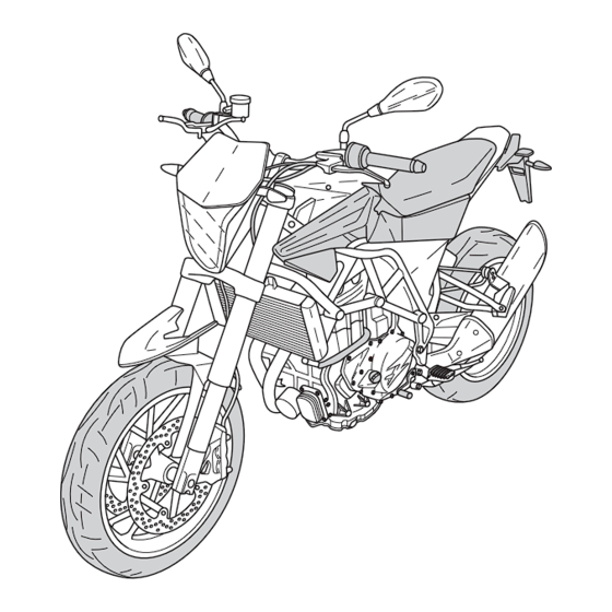
Page 9: Motorcycle Overall View
MOTORCYCLE OVERALL VIEW SPECIFICATIONS - OPERATION - MAINTENANCE EN - 9... - Page 10 29. Fuel tank filler cap 30. Digital dashboard 31. Ignition switch 32. Right-hand switch 33. ENGINE STOP button (emergency stop) 34. Engine start button 35. Front brake control lever 36. Throttle twistgrip 37. Clutch control lever 38. Left-hand switch EN - 10 SPECIFICATIONS - OPERATION - MAINTENANCE...
-
Page 11: Controls
CONTROLS SIDE STAND A side stand (1) is supplied with every motorcycle. To REFUELLING lower it, put your foot on the lever (2). UNLEADED petrol with octane rating of 95 or higher only. WARNING*: The stand is designed to support the CAUTION*: WEIGHT of the MOTORCYCLE ONLY. -
Page 12: Combined Dashboard
COMBINED DASHBOARD The motorcycle has a combined dashboard divided into the following areas: 1. Warning lights (see “Description of warning lights”). 2. Multifunction display (see “ Description of multi- function display”). 3. Rev meter Indicates the engine rpm. 4. Alarm system warning light (RED). 5. - Page 13 This indicates that it is time for a service. This flashes when the turning indicators have has been pressed. Contact your HUSQVARNA dealer to have sched- been turned on or the “HAZARD” button has uled maintenance work carried out. been pressed.
-
Page 14: Clock Adjustment
Clock adjustment is automatically memorised after 10 seconds. > 4” The clock must be set when the motorcycle is stationary and the key is set to ON. Setting units of measurement The clock is set to 24 hours. The units of measurement must be set when the motorcy- cle is stationary and the key is set to ON. - Page 15 Setting parameters CON function: Changing ECU mapping: When this function is activated, press the “S” button for The vehicle leaves the factory in “STANDARD” configura- With the dashboard on, press the “S” button (1) to dis- more than 4 seconds to reset and start a new count of the tion, i.e, with maximum power.
- Page 16 THROTTLE CONTROL FRONT BRAKE CONTROL IGNITION SWITCH The throttle twistgrip (1) is located on the right-hand side The brake control lever (1) is located on the right-hand of the handlebar. The position of the control on the han- The ignition switch has three positions: side of the handlebar.
- Page 17 RIGHT-HAND HANDLEBAR SWITCH STEERING LOCK The right-hand switch features the following controls: The motorcycle has a steering lock on the ignition. 1) Engine start button To lock it, proceed as follows: 2) Engine KILL SWITCH. - Turn the handlebar as far as possible to the left . - Insert the key in the ignition (1), press the key down, turn it from the “OFF”...
- Page 18 CLUTCH CONTROL REAR BRAKE CONTROL GEAR SHIFT CONTROL The clutch control lever (1) is located on the left-hand The lever (1) is placed on the left-hand side of the en- The rear brake control (1) is placed on the right-hand side of the handlebar.
-
Page 19: Riding
INSTRUCTIONS FOR USING THE MOTORCY- Optimum performance during accelera- Recommended maximum engine rpm: tion is only obtained after the first 1000 km (mi) covered km (625 mi) of running in. 0-1000 (0-625) .............7000 NOTE*: If you are not familiar with op- Follow these guidelines: over 1000 (625) ...........9000 erating a motorcycle, read the instruc-... - Page 20 - Faulty spark plug or wrong heat rating: replace. In any case, contact your authorised Husqvarna dealer The alternator fails to charge or its charge is insufficient. who has the experience and expertise required to provide - The cables on the voltage regulator are badly con- you with all the assistance you need.
- Page 21 Mounting of passenger MOUNTING/DISMOUNTING OF RIDER AND PASSENGER - Start the motorcycle as described in the relevant sec- tion. Get the rider to mount first as described in the relevant - Using your left leg, fully retract the stand. section without starting the engine. General Read the following section carefully since it provides im- - Get the passenger to put the passenger footrests (1)
- Page 22 Dismounting the motorcycle Place your left hand on the rider's shoulder, your left - Stop the vehicle and switch off the engine. foot on the footrest and then mount the motorcycle by lifting your right leg and moving carefully to avoid CAUTION*: unbalancing the vehicle and the rider.
- Page 23 STARTING THE ENGINE 1) Turn key (1) in the ignition switch to ON (the hum you may hear when key is turned to ON is caused by the fuel pump pressurising the delivery system), and wait until the dashboard CHECK has finished; 2) pull clutch lever (2);...
- Page 24 RIDING YOUR MOTORCYCLE 3) With the throttle (1) closed and the engine idling, pull the clutch lever (2) and push the gear lever (3) WARNING*: down to select the first gear. Before setting off make sure that: 4) Slowly release the clutch lever (2) and, at the same - the side stand is fully up;...
- Page 25 - Release the clutch gradually when downshifting. SAFE RIDING - If you feel tired or sleepy, take a break. Here are some basic principles for riding your motor- - Downshift in the following instances: cycle safely. When going downhill and when braking to increase the braking action through engine compression;...
- Page 26 STOPPING THE MOTORCYCLE AND THE ENGINE - To stop the engine, turn key (6) to OFF (key removal position). - Close the throttle (1) completely so that the engine will help slow down the motorcycle. - Apply both front (2) and rear (3) brakes while down- shifting (for fast deceleration, press firmly on the front brake lever and the rear brake pedal simulta- neously).
- Page 27 IMMEDIATELY depress the HUSQVARNA Dealer. engine kill switch (7). Control the motorcy- cle by normal use of the brakes and steer- ing while pressing the engine kill switch.
- Page 28 MIN and MAX marks on the expan- We recommended having this done at an authorised sion tank (1) on the right side of the vehicle. HUSQVARNA dealer. WARNING*: Be careful not to touch hot engine oil. Drain the oil with WARM ENGINE; proceed as follows: Place the motorcycle on the side stand;...
- Page 29 - Lift the flap (4), insert the key (5), turn it counter- - Remove the air box cover (7) by unscrewing the - Turn the saddle locking screw 90° counterclockwise clockwise and remove the tank cap (6). screws (8). using the wrench (2). - Remove the saddle (3) by lifting it up at the back - Remove the right-hand side panel (9) by unscrewing the screws (10).
- Page 30 WARNING AIR FILTER CHECK - Remove the saddle (2) by lifting it up at the back Do not remove the radiator cap (11) and slide it towards the rear of the vehicle by un- - Remove the Allen wrench (1) provided on the right since all the liquid in the expansion hooking it off the front brackets.
- Page 31 - Remove the air box cover (6) by unscrewing the - Unscrew the screws (10) on the filter cover (11) and - Remove the filter (12), check that it is not clogged and remove it. replace if necessary. screws (7). CAUTION*: Before refitting the filter, check that the contact surfaces between the filter, the...
- Page 32 CAUTION*: The fluid level in the master cylinder tank shall never be the Husqvarna Dealer. Brake fluid may cause irritation. Avoid below the minimum level (3) shown on the transparent contact with skin or eyes. In case of con- reservoir (4).
- Page 33 Since it is dangerous to operate the mo- torcycle under such conditions, have the brake system immediately checked by the Husqvarna Dealer. CAUTION*: Do not spill brake fluid onto any painted surface or light lens.
- Page 34 CLUTCH FREE PLAY ADJUSTMENT CLUTCH CONTROL LEVER DISTANCE ADJUSTMENT SUSPENSION The lever (1) distance on the handlebar can be adjusted Free play (A) must be 5 -10 mm (0.196 - 0.39 in). The vehicle leaves the factory with standard settings for according to the size of the rider's hand.
-
Page 35: Suspension Settings Summary Tables
SUSPENSION SETTINGS SUMMARY TABLES SHOCK ABSORBER NUDA 900 NUDA 900 NUDA 900 R NUDA 900 R NUDA 900 R with panniers and passenger Motard with panniers and passenger Length of shock absorber "A" 380 mm (14,96 in) 385 mm (15,15 in) 380 mm (14,96 in) Shock absorber compression adjustment 16 clicks... - Page 36 FORK ADJUSTMENT FOR "NUDA 900 R" ONLY b) REBOUND (TOP ADJUSTER) Standard setting: 10 clicks a) COMPRESSION (LOWER ADJUSTER) Standard setting: 6 clicks To reset standard calibration, turn adjuster screw (B) clockwise to reach the fully closed position and then turn To reset standard calibration, turn adjuster screw (A) it back the number of clicks specified above.
- Page 37 A) COMPRESSION - Standard setting: SHOCK ABSORBER SPRING PRELOAD ADJUSTMENT SHOCK ABSORBER HYDRAULIC DAMPING ADJUSTMENT - 16 clicks (± 2 clicks) Nuda 900 (adjuster 4) Nuda 900 It is possible to adjust the rebound travel of the shock To adjust the spring preload, contact an authorised HUSQ- B) REBOUND - Standard setting: absorber.
- Page 38 CHAIN ADJUSTMENT If this is not the case, proceed as follows: - make sure that the motorcycle is fully upright on the Chain should be checked, adjusted and lubricated as per special rear support stand (optional). the Maintenance Chart to ensure safety and prevent ex- - on the left side, loosen the locking nut (3) of the wheel cessive wear.
- Page 39 CHECKING CHAIN AND SPROCKETS FOR WEAR TYRES Check that the chain does not have damaged rollers, loose Care should be taken to keep the tyres properly inflated. pins or dry, rusty links and is not excessively worn. See "Technical data" chart at the beginning of the manu- al for correct tyre inflation pressure.
- Page 40 BRAKES The key components of the braking systems are: brake master cylinder with its lever (front) or pedal (rear), brake lines, calliper assembly and disc. LEGEND Front brake control lever Front brake master cylinder with fluid reservoir 3. Front brake line 4.
- Page 41 Note *: For the Nuda 900 R version, a series of front brake pads with a more aggressive compound is available as a spare; for more information, contact an authorised HUSQVARNA dealer. Nuda 900 R Nuda 900 4 mm 0,16 in.
- Page 42 When electrolyte leaks, or other failure of the electrical - remove the cover (2); system is detected, apply to the HUSQVARNA Dealer. Always check the battery charge before reinstalling it on - first remove the BLACK or BLUE negative cable, then If the vehicle remains unused for long periods, it is rec- the vehicle.
- Page 43 FRONT HEADLAMP BULB REPLACEMENT To replace the parking light bulb: - Loosen the two screws (6) and remove the cover (7); Proceed as follows to reach the headlamp bulbs: - Detach the bulb holder (8) and remove the light bulb (9). - Undo the two upper screws (1);...
- Page 44 TURNING INDICATOR BULB REPLACEMENT TAIL LIGHT REPLACING THE NUMBER PLATE BULB - loosen screw (1) and remove the number plate bulb The tail light (1) is a LED light; if it does not work prop- - Loosen screw (1) using a Phillips screwdriver; (2) from the mudguard;...
- Page 45 HEADLIGHT ADJUSTMENT Beam height can be adjusted as follows: When checking the proper aiming of the headlight beam: - Turn the adjuster screw (1) on the left side of the head- inflate tyres at the right pressure, have a person sit light unit;...
-
Page 46: Appendix
APPENDIX CLEANING - Wash the motorcycle with a low-pressure water jet to re- move any dust and mud. The bodywork must be cleaned LONG PERIOD OF INACTIVITY Cleaning the vehicle is very important especially if it is with a soft sponge and a water and bodywork shampoo When the motorcycle is to be stored for a certain period, used in special areas or conditions such as: solution. - Page 47 CAUTION*: After washing, braking efficiency could be After washing: AVOID USING HIGH-PRESSURE WATER OR temporarily reduced due to the presence - Lubricate the drive chain, the lever and pedal controls AIR JETS on the ELECTRICAL COMPONENTS of water on the friction surfaces of the and the clutch cable.
-
Page 48: Pre-Delivery Inspection
PRE - DELIVERY INSPECTION DESCRIPTION OPERATION PRE-DELIVERY Engine oil Check level Coolant Check Cooling system Check for leakage Electric fans Check operation Brakes fluid Check level Brakes Check operation Throttle control Check operation / Clearance Flexible controls and transm. Check / Adjust Drive chain Check / Adjust Tyres... - Page 49 ALPHABETIC INDEX Page GEAR SHIFT CONTROL ..............18 SAFE RIDING ..................25 GENERAL RECOMMENDATIONS ............4 SETTING PARAMETERS ..............15 AIR FILTER CHECK ................30 SETTING UNITS OF MEASUREMENT ...........14 APPENDIX ..................46 SHOCK ABSORBER HYDRAULIC DAMPING ADJUSTMENT ....37 HEADLIGHT ADJUSTMENT ..............45 SHOCK ABSORBER SPRING PRELOAD ADJUSTMENT ......37 SIDE STAND ..................11 BATTERY ..................42 STARTING THE ENGINE ..............23...