Pioneer AVH-P5200BT Service Manual
Dvd av receiver
Hide thumbs
Also See for AVH-P5200BT:
- Operation manual (96 pages) ,
- Installation manual (32 pages) ,
- Operation manual (96 pages)
Table of Contents
Advertisement
Quick Links
DVD AV RECEIVER
AVH-P5200BT
AVH-P5250BT
AVH-P5200DVD
AVH-P5250DVD
AVH-P5250DVD
AVH-P5250DVD
This service manual should be used together with the following manual(s):
Model No.
Order No.
CX-3268
CRT4534
For details, refer to "Important Check Points for Good Servicing".
PIONEER CORPORATION
PIONEER ELECTRONICS (USA) INC. P.O. Box 1760, Long Beach, CA 90801-1760, U.S.A.
PIONEER EUROPE NV Haven 1087, Keetberglaan 1, 9120 Melsele, Belgium
PIONEER ELECTRONICS ASIACENTRE PTE. LTD. 253 Alexandra Road, #04-01, Singapore 159936
PIONEER CORPORATION 2010
Mech.Module
MS7
DVD Mech. Module : Circuit Descriptions, Mech. Descriptions, Disassembly
1-1, Shin-ogura, Saiwai-ku, Kawasaki-shi, Kanagawa 212-0031, Japan
AVH-P5200BT/XNUC
/XNRD
/XNUC
/XNRC
/XNRD
/XNRI
Remarks
ORDER NO.
CRT4537
/XNUC
K-ZZZ. MAR. 2010 Printed in Japan
Advertisement
Table of Contents

Related Manuals for Pioneer AVH-P5200BT


Summary of Contents for Pioneer AVH-P5200BT
- Page 1 PIONEER CORPORATION 1-1, Shin-ogura, Saiwai-ku, Kawasaki-shi, Kanagawa 212-0031, Japan PIONEER ELECTRONICS (USA) INC. P.O. Box 1760, Long Beach, CA 90801-1760, U.S.A. PIONEER EUROPE NV Haven 1087, Keetberglaan 1, 9120 Melsele, Belgium PIONEER ELECTRONICS ASIACENTRE PTE. LTD. 253 Alexandra Road, #04-01, Singapore 159936 PIONEER CORPORATION 2010 K-ZZZ.
-
Page 2: Safety Information
When Q1103 or Q1104 is shorted between their terminals, the laser diodes for DVD or CD will radiate beam. If the top cover is removed with no disc loaded while such short-circuit is continued, the naked eyes may be exposed to the laser beam. AVH-P5200BT/XNUC... - Page 3 CAUTION Danger of explosion if battery is incorrectly replaced. Replaced only with the same or equivalent type recommended by the manufacture. Discord used batteries according to the manufacture's instructions. AVH-P5200BT/XNUC...
- Page 4 To protect products from damages or failures during transit, the shipping mode should be set or the shipping screws should be installed before shipment. Please be sure to follow this method especially if it is specified in this manual. AVH-P5200BT/XNUC...
-
Page 5: Table Of Contents
11.2 TUNER BOX UNIT..........................180 11.3 DVD CORE UNIT(MS7)........................182 11.4 COMPOUND UNIT(A) AND COMPOUND UNIT(B) ................186 11.5 PANEL PCB ............................188 11.6 KEYBOARD PCB..........................189 11.7 MONITOR PCB.............................190 11.8 BT PCB ..............................194 11.9 BT ANT PCB............................195 11.10 DRIVE UNIT............................196 12. ELECTRICAL PARTS LIST.........................197 AVH-P5200BT/XNUC... -
Page 6: Service Precautions
“Plug the supplied microphone securely into the jack” may appear due to the measurement failure. 11. EJECT LOCK MODE for DVD mechanism How to enter : Reset with [FORWARD] key and [EJECT] key pressed. Unlocked by turning ACC ON or reset. AVH-P5200BT/XNUC... -
Page 7: Notes On Soldering
Compared with eutectic solders, lead-free solders have higher bond strengths but slower wetting times and higher melting temperatures (hard to melt/easy to harden). The following lead-free solders are available as service parts: Parts numbers of lead-free solder: GYP1006 1.0 in dia. GYP1007 0.6 in dia. GYP1008 0.3 in dia. AVH-P5200BT/XNUC... -
Page 8: Specifications
2. SPECIFICATIONS 2.1 SPECIFICATIONS AVH-P5200BT/XNUC, AVH-P5200DVD/XNUC General Slope........–12 dB/oct Subwoofer (mono): Power source......14.4 V DC (10.8 V to 15.1 V Frequency......50/63/80/100/125 Hz allowable) Slope........–18 dB/oct Grounding system....Negative type Gain ........+6 dB to –24 dB Maximum current consumption Phase .........Normal/Reverse ............10.0 A... - Page 9 Frequency range..... 530 kHz to 1 710 kHz (10 kHz) Usable sensitivity....25 μV (S/N: 20 dB) Signal-to-noise ratio....62 dB (IHF-A network) Bluetooth (AVH-P5200BT) Version ........Bluetooth 2.0 certified Output power ......+4 dBm Max. (Power class 2) CEA2006 Specifications Power output ......14 W RMS ×...
- Page 10 Frequency......40/80/200/400/1k/2.5k/8k/ (Ver. 8.2 and earlier) 10k Hz DivX decoding format....Home Theater Ver. 3, 4, 5.2, Gain ........±12 dB 6 (.avi, .divx) HPF: Frequency......50/63/80/100/125 Hz Slope........–12 dB/oct Compatible physical format Subwoofer (mono): ...........Version 1.1 Frequency......50/63/80/100/125 Hz AVH-P5200BT/XNUC...
- Page 11 530 kHz to 1 640 kHz (10 kHz) Usable sensitivity....25 μV (S/N: 20 dB) Signal-to-noise ratio....62 dB (IEC-A network) Infrared remote control Wavelength........945 nm Output ......... typ; 10 mw/sr per Infrared Note Specifications and the design are subject to mod- ifications without notice. AVH-P5200BT/XNUC...
- Page 12 ..........Version 1.1 Gain ........±12 dB Maximum memory capacity HPF: ..........2 GB Frequency....... 50/63/80/100/125 Hz File system......FAT12, FAT16, FAT32 Slope........–12 dB/oct MP3 decoding format ..MPEG-1 & 2 Audio Layer 3 Subwoofer (mono): Frequency....... 50/63/80/100/125 Hz Slope........–18 dB/oct AVH-P5200BT/XNUC...
- Page 13 Version ........Bluetooth 2.0 certified Output power ......+4 dBm Max. (Power class 2) Infrared remote control Wavelength......945 nm Output ........typ; 10 mw/sr per Infrared Note Specifications and the design are subject to mod- ifications without notice. AVH-P5200BT/XNUC...
-
Page 14: Disc/Content Format
(BT model only) The Bluetooth word mark and logos are owned by the Bluetooth SIG, Inc. and any use of such marks by Pioneer Corporation is under license. Other trademarks and trade names are those of their respective owners. AVH-P5200BT/XNUC... -
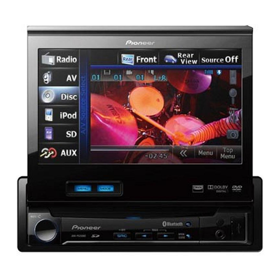
Page 15: Panel Facilities
2.3 PANEL FACILITIES Head unit CAUTION • Use an optional Pioneer USB cable (CD-U50E) to connect the USB audio player/USB mem- ory as any device connected directly to the unit will protrude out from the unit and may be dangerous. -
Page 16: Remote Control
Press to return to the Press and hold to turn previous track (chap- the rear source off. ter). Press to go to the next track (chapter). Press to stop play- back. Press to select the / (FOLDER/P.CH) next/previous disc/ folder. AVH-P5200BT/XNUC... -
Page 17: Connection Diagram
2.4 CONNECTION DIAGRAM AVH-P5200BT/XNUC, AVH-P5200DVD/XNUC AVH-P5200BT/XNUC... - Page 18 AVH-P5200BT/XNUC...
- Page 19 AVH-P5200BT/XNUC...
- Page 20 AVH-P5250BT/XNRD, AVH-P5250DVD/XNRC, AVH-P5250DVD/XNRI, AVH-P5250DVD/XNRD AVH-P5200BT/XNUC...
- Page 21 AVH-P5200BT/XNUC...
- Page 22 AVH-P5200BT/XNUC...
- Page 23 AVH-P5200BT/XNUC...
-
Page 24: Basic Items For Service
For check items concerning image and voice, please refer to the followings: Check items concerning image Check items concerning voice Block-noise Distortion Crosscut noise Noise Dot noise Low volume Distorted image (Image skip) High volume Low brightness Changes in level Too bright Pause of sound Color fading Partial discoloration AVH-P5200BT/XNUC... -
Page 25: Pcb Locations
Switch PCB Unit Panel PCB DVD Amp Unit Main PCB Unit BT Model Monitor PCB Volume PCB Unit Keyboard PCB Switch PCB Unit Panel PCB DVD Amp Unit (Service) Main PCB Unit BT PCB BT ANT PCB Tuner Box Unit AVH-P5200BT/XNUC... - Page 26 H:AVH-P5200BT/XNUC I:AVH-P5250BT/XNRD B:AVH-P5200DVD/XNUC C:AVH-P5250DVD/XNRC D:AVH-P5250DVD/XNRD E:AVH-P5250DVD/XNRI Unit Number CXX2838(H) Unit Number CXX2839(I) Unit Name DVD Amp Unit(Service) Unit Number CWN4979(B) Unit Number CWN4980(C) Unit Number CWN4981(D) Unit Number CWN4982(E) Unit Name DVD Amp Unit Unit Number CWN3129(H,B) Unit Number CWN3130(I,C,D,E)
-
Page 27: Jigs List
DVD Mechanism Module and Drive Unit Grease GEM1043 DVD Mechanism Module and Drive Unit Locking agents 1401M DVD Mechanism Module (1401M:produced by THREE BOND) Grease GEM1011 Drive Unit Grease GEM1047 Drive Unit Grease GEM1071 Drive Unit Grease GEM1072 Drive Unit AVH-P5200BT/XNUC... -
Page 28: Cleaning
Before shipping out the product, be sure to clean the following portions by using the prescribed cleaning tools: Portions to be cleaned Cleaning tools DVD pickup lenses Cleaning liquid : GEM1004 Cleaning paper : GED-008 Portions to be cleaned Cleaning tools Fans Cleaning paper : GED-008 AVH-P5200BT/XNUC... - Page 29 AVH-P5200BT/XNUC...
-
Page 30: Overall Connection Diagram
GNDD ILMB GNDD GNDD 5 KEY1 CN961 LEDR1 PWRVI 3 PWRVI CN5701 CN5101 LEDG1 PWRVI PWRVI 2 CKS6180-A CKS5561-A CKS5561-A PWRVI 1 PWRVI LEDB1 GND3 GND5 CD/WP SD CARD TOUCH PANEL BACK LIGHT GND4 GND6 CN3001 CKS5858-A JA3001 CKN1084-A AVH-P5200BT/XNUC... - Page 31 NC 2 RDSLOCK 1 UNIT (MMD PART) CN751 CKS6025-A GNDD UNIT (I/F PART) GNDD GNDD IECOUT GNDD BT model GNDD VGND AVH-P5200BT/XNUC COMPOSIT AGND LOUT AGND AVH-P5250BT/XNRD ROUT AGND STANBY MS7 SRX S MS7TX IRGPWR XRESET AMUTE GNDD PGND PGND...
- Page 32 IC301 BUSL- HA12241FP ASENBO IP BUS S_to_IP S_to_IP BUS+ 6 BUS+ S_to_IP DIN1 IP_to_S IP_to_S BUS- PNLVD IP_to_S BUS- ROUT PNLADX CN331 PNLADY ONSEI+ ONSEI- Q601 RGBARI RGBARI /RGBARI TVON ASENBO ASENBO ASENBO NAVI I/F CCSYNC Q301 BUP_1 ASENBO AVH-P5200BT/XNUC...
- Page 33 PNLYV Q981 PWRVI PWRVI ILMB ILMB RGB VIDEO ISOLATOR PNLVD PNLVD PWRBL IC351 PWRBL NJM2138V PNLADX CN5002 N_CSYNC CCSYNC CSYNC PNLADY ANAR : AVH-P5200BT/XNUC : AVH-P5250DVD/XNRC ANAG : AVH-P5250BT/XNRD : AVH-P5250DVD/XNRD : AVH-P5200DVD/XNUC : AVH-P5250DVD/XNRI ANAB MONVBS CN2021 (1/2) AVH-P5200BT/XNUC...
-
Page 34: Panel Pcb
(1/2) IC602 (1/2) LEDR1 LED_R LED_R RESET ILMB PE5721A8 IC601 LED_G LED_G LEDG1 Q3001 S-80827CNNB-B8M LED_B LED_B PE5723A8 (2/2) LEDB1 Q3002 VCC33 VCC33 VCC33 VCC33 ILM+B ILM+B ILMB ILMB D3010 Q3003 (1/2) LEDR2 ILMB LEDG2 Q3003 (2/2) LEDB2 Q3004 AVH-P5200BT/XNUC... - Page 35 SDDAT2 DAT2 USB_D- SDDAT2 UCOM SDDAT3 CD/DAT3 SDDAT3 (1/2) USB+ SDCLK CARD USB_D+ SDCLK SDDET 5721A8 SDCD PE5723A8 Q961 VCC33 VCC33 G_to_D G_to_D D_to_G D_to_G DGCLK DGCLK : AVH-P5200BT/XNUC : AVH-P5250DVD/XNRC : AVH-P5250BT/XNRD : AVH-P5250DVD/XNRD : AVH-P5200DVD/XNUC : AVH-P5250DVD/XNRI AVH-P5200BT/XNUC...
- Page 36 STEPPER2 DRV3 X1501 SL2IN STEPPER1 27 MHz HVP (HV+), HVM (HV-) OSCI FCO+ HWP (HW+), HWM (HW-) VDSENS FCO- HALL_BIAS- TKO- HALL_VC HALL_BIAS+ TKO+ 45 VCC5 VREFH VREF VIN6 HOME VIN5 SLO1+ SLO1- STEPPING MOTOR SLO2+ SLO2- SWITCH HOME AVH-P5200BT/XNUC...
- Page 37 S1205 12cm IC1004 PHOTOSNS Photo NJM2885DL1-33 VCC33 VDD5 1.2V REG. IC1005 R1232D121B VDD5 VCC12 VOUT CN1101 Vref VREF VCC5 F+H_G+H F+H/G+H E+G_E+F E+G/E+F Q1102 Q1104 78LD(CD) LPCO2 Q1101 Q1103 LPCO1 65LD(DVD) PU (DP8.6) VREF CDMPD 78MD DVDMPD 65MD TEMP AVH-P5200BT/XNUC...
- Page 38 GPI013 IC5503 ILMB ILMB GPI012 TC7SHU04FUS1 PWRBL PWRBL OUTY LCDICLK OSCXO X5501 MBLPW 33 MHz BLERR1 OSCXI BLCLK DIMPLS X5502 9.597 MHz TEMP TEMP1 MBLPW BLERR1 IC5702 TC7SET08FUS1 BLCLK OUTY Q5705 DIMPLS TEMP1 (1/2) Q5801 (2/2) Q5801 KEY1 Q5802 AVH-P5200BT/XNUC...
- Page 39 X5502 9.597 MHz CN5701 Q5703 Q5701 Q5702 IC5702 LCD BACKLIGHT C7SET08FUS1 FAULT LED4 LED4 CLKI LED3 OUTY LED3 LED2 LED2 Q5705 LED1 LED1 IC5701 TK61222CQ6 TEMP1 CN5802 (1/2) Q5801 LEDR1 LEDG1 LEDB1 KEY1 (2/2) Q5801 CN3500 ILMB ILMB Q5802 AVH-P5200BT/XNUC...
-
Page 40: Diagnosis
ASENBO <- H DDCCLK <- Clock Out DDCCLK : Pin92 (Frequency of 370 kHz) VD5 <- H VD5, 8 : Pin113, 114 VD8 <- H Starts Communication with Display microcomputor Source Keys operartive Source ON SYSPW : Pin130 SYSPW <- H AVH-P5200BT/XNUC... -
Page 41: Inspection Method Of Pickup Unit
To “Replace pickup” Check 3 Check measured value of error ratio * Make sure to avoid any unwiped spots or actuator breakage. Check error ratio Lens cleaning Clean lens Within prescribed completed? value? To “Replace pickup” No problem found in pickup AVH-P5200BT/XNUC... - Page 42 Remarks: LD current value (ref.) GGV1025 DVDLD1-VCC5_3 60~390(mV) 10~65(mA) DVDLD1 VCC5_3 Disc used Spot to check Rated value Remarks: LD current value (ref.) TCD-782 CDLD1-VCC5_3 60~360(mV) 10~60(mA) VCC5_3 CDLD1 Mind breakage of a laser diode caused by static electricity. AVH-P5200BT/XNUC...
- Page 43 Check the error ratio of a specified ID in the tracking closed status in the test mode. Disc used Spot to check Rated value Remarks: GGV1025 ID : 40000 1.000E-3 or less GGV1025 ID : 200000 1.000E-3 or less TCD-782 ID : Home position 2.500E-3 or less Error ratio: 0.742E-5 in this case AVH-P5200BT/XNUC...
-
Page 44: Diagnosis Flowchart
IC but a core unit (as no key or others is written in a Go to FE Check flash alone). Normal? Go to FE Check Go to FE-related FE part normal? repair Replace unit Normal? AVH-P5200BT/XNUC... - Page 45 Check the voltage of the sending pin when the power is ON. Checking should be based on DGND. Spot to check Module NO. Rated value Unit 1 STANDBY-DGND1 VCC33-0.6V or more PCB side A STANDBY DGND1 Fig. 1.1: Spots to check in STANDBY AVH-P5200BT/XNUC...
- Page 46 Unit 1 VDD5_2 - DGND1 5.0 ± 0.4 2 VCC33_1 - DGND1 3.3 ± 0.15 3 VCC12-1 - DGND1 1.2 ± 0.12 PCB side A VCC12-1 VDD5_2 VCC33_1 DGND1 Fig. 2.2: Spots to check in VDD5, VCC33, VCC12 voltages AVH-P5200BT/XNUC...
- Page 47 Check the voltage of the sending pin when the power is ON. Checking should be based on DGND. Spot to check Module NO. Rated value Unit 1 NRES-DGND1 VCC33 x 0.7 or more PCB side A NRES DGND1 Fig. 3.1: Spots to check in RESET AVH-P5200BT/XNUC...
- Page 48 Check the voltage of the sending pin when the power is ON. Checking should be based on DGND. Spot to check Module NO. Rated value Unit 1 VSENS - DGND1 VCC33 x 0.7 or more PCB side A DGND1 VSENS Fig. 4.2: Spots to check in VSENS AVH-P5200BT/XNUC...
- Page 49 Spot to check Module NO. Rated value Unit 1 IC1501 156pin 27 MHz ± 50ppm Rated value Fig. 5.2: Rated value of a clock PCB side A DGND1 IC1501 156pin Fig. 5.3: Spots to check in 27 MHz AVH-P5200BT/XNUC...
- Page 50 34 DQM0 IC1480 15pin IC1501 179pin 56 ohm ± 5% 35 DQM1 IC1480 39pin IC1501 180pin 56 ohm ± 5% 36 BA0 IC1480 20pin IC1501 193pin 56 ohm ± 5% 37 BA1 IC1480 21pin IC1501 197pin 56 ohm ± 5% AVH-P5200BT/XNUC...
- Page 51 PCB side B Spot to check 1 (IC1480) PCB side A Spot to check 2 (IC1501) Fig. 6.2: Spots to check in SDRAM I/F AVH-P5200BT/XNUC...
- Page 52 Rated value Unit 1 VD8_1 - PGND3 8.0 ± 0.4 2 VD - PGND_3 8.0 ± 0.4 3 VCC5_1 - AGND1 5.0 ± 0.1 PCB side A VD8_1 PGND3 AGND1 VCC5_1 Fig. 7.2: Spots to check in VD8, VCC5 voltages AVH-P5200BT/XNUC...
- Page 53 Checking should be based on PGND, AGND. Spot to check Module NO. Rated value Unit 1 VD - PGND_3 8.0 ± 0.4 2 AVCC5 - GNDAU1 5.0 ± 0.1 PCB side A PGND3 GNDAU1 AVCC5 Fig. 8.2: Spots to check in VD8, AVCC5 voltages AVH-P5200BT/XNUC...
- Page 54 Rated value 3 1 DACCK 2.0 V~VCC33V DGND~0.8 V 36.8640 MHz ± 300 ppm 2 DACCK 2.0 V~VCC33V DGND~0.8 V 33.8688 MHz ± 300 ppm Rated value 1 Rated Rated value 2 value 3 Fig. 9.2: Rated value of a clock AVH-P5200BT/XNUC...
- Page 55 PCB side A Spot to check 2 (IC1501 148pin) Spot to check 1 (probe) Fig. 9.3: Spots to check in 27 MHz, DACCLK AVH-P5200BT/XNUC...
- Page 56 VCC33V-0.6V or more 0.4V or less Waveform 1 2 SRCK VCC33V-0.6V or more 0.4V or less Waveform 2 3 LRCK VCC33V-0.6V or more 0.4V or less Waveform 3 Rated value 2 Rated value 1 Fig. 10.2: Rated value of serial three wires AVH-P5200BT/XNUC...
- Page 57 Spot to check 1 (sending pin) Rated value (rms) Reference waveform 4 LO 1400 ± 150 mV Waveform 4 5 RO 1400 ± 150 mV Waveform 4 Rated value is an effective value (rms) Fig. 10.4: Rated value of analog audio out (LO, RO) AVH-P5200BT/XNUC...
- Page 58 Checking should be performed after connecting 24Pin FFC to the jig or other equipment. Spot to check 1 (sending pin) Rated value 1 Rated value 2 Reference waveform 6 IEC VCC33V-0.6V or more 0.4V or less Waveform 5 PCB side A Fig. 10.6: Spot to check in digital audio signal (IECOUT) AVH-P5200BT/XNUC...
- Page 59 PEAK COMPOSITE signal Rated value Color burst Pedestal level BOTTOM Horizontal synchronous signal Fig. 11.2: Waveform when 100% composite white is output PCB side A COMPOSITE Fig. 11.5: Spot to check in VIDEO signal AVH-P5200BT/XNUC...
- Page 60 (For how to display the LD live time, see FE Test Mode) 2. The second digit of the live time from the left being E as in “*E** ****” means the FLASH memory has reached the end of its life. E.g.: AVH-P5200BT/XNUC...
- Page 61 Reference voltage: DGND2 1 V/div. 5 usec/div Reference voltage: DGND2 1 V/div. 500 nsec/div Waveform 2 Waveform 5 CH1 : LRCK Reference voltage: DGND2 1 V/div. 5 usec/div Waveform 3 VIDEO [WHITE 100IRE] CH1 : COMPOSITE Reference voltage: GNDV1 200 mV/div. 10 usec/div Waveform 6 AVH-P5200BT/XNUC...
-
Page 62: Error Code List
*4 Available only for the models compatible with DVD-A. In case of an error, the audio output will be muted only but the playback operation will continue. Also, acceptance of the user operation will be the same as normal. AVH-P5200BT/XNUC... - Page 63 The time taken for occurrence should be specified in the latency time for the audio property notice set in the connection confirmation command. *10 This occurs when the DRM information update notice is sent from the DVD mecha but no DRM information update response is returned. AVH-P5200BT/XNUC...
-
Page 64: Error Messages
AVH-P5200BT/XNUC... - Page 65 AVH-P5200BT/XNUC...
-
Page 66: Connector Function Description
24. SYS_TO_NAVI 9. BUSR+ 10. BGSENS 10. CCAUL 25. NAVI_TO SYS 10. BUSR- 26. GNDD 11. ACC 11. CCAUR 11. BUSL- 12. B.REM 12. GNDAU 13. ILM 13. ONSEI+ 14. MUTE 14. ONSEI- 15. B.UP 15. NC 16. GND AVH-P5200BT/XNUC... -
Page 67: Service Mode
6. SERVICE MODE 6.1 DVD TEST MODE AVH-P5200BT/XNUC... - Page 68 AVH-P5200BT/XNUC...
- Page 69 AVH-P5200BT/XNUC...
- Page 70 AVH-P5200BT/XNUC...
- Page 71 AVH-P5200BT/XNUC...
- Page 72 AVH-P5200BT/XNUC...
- Page 73 Middle DVD: Middle Select CD Search destination CRG home position 5 Select CRG Move Select completed Select 5 Select Return CRG transfers to the outermost circumference <In case of an error> Select <In case of an error in Power_OFF> AVH-P5200BT/XNUC...
- Page 74 Test mode command NULL * In CRG+/-, operation stops when the key is released. At that time, the DVD mecha should make the key command request (TP = B1h) on a regular basis to prevent any omission of key release. AVH-P5200BT/XNUC...
- Page 75 D1 = 03h, set the TE offset coefficient to D2 – D9 and transmit [1 second later] D1 = 07h, set the DBAL coefficient to D2 – D9 and transmit [1 second later] D1 = 01h, after setting the status display data to D2 – D9 and transmitting, wait for keys AVH-P5200BT/XNUC...
- Page 76 End displaying RF level value Tracking Close status (3),(4) Measure Switch playback Power Off Focus Jump ID Search T.Jump Tracking Open error ratio speed Note 3 Note 4 (1)-(4) Specify No. Specify ID of tracks Start ID search Start jumping AVH-P5200BT/XNUC...
- Page 77 Register set time set time [How to specify a set time] Specify a digit with the commands (1) and (2). Commands (3) and (4) are to increase/decrease the number. Determine with the command (5). Cancel with the command (8). AVH-P5200BT/XNUC...
-
Page 78: Monitor Test Mode
Choose "Version Check" among the monitor test mode menu screen. [Display specifications] When 8 digits of read number is strange, displayed with red. [Operation specification] Operational description Remote controller key Return to test mode menu Page up Page down AVH-P5200BT/XNUC... - Page 79 In case the EEPROM initialization has been performed. In case the adjustment value has been initialized. Calibration inspection : In case the calibration inspection has never been performed. In case the EEPROM initialization has been performed. In case the adjustment value has been initialized. AVH-P5200BT/XNUC...
- Page 80 X/Y information of [MIN] and [MAX] of the outermost circumference are displayed. [BEFOR] indicates the value stored in the EEPROM. [AFTER] indicates MIN/MAX of the A/D value currently captured. [Operation specification] Operational description Remote controller key Return to top menu AVH-P5200BT/XNUC...
- Page 81 Order of display of the locations to be pressed. This point is intended to end the calibration inspection, and therefore, the corrected value of this point is not obtained. [Operation specification] Operational description Remote controller key Return to top menu AVH-P5200BT/XNUC...
- Page 82 : The coordinate (X direction, Y direction) which is the result of adding the correction by calibration to the normalized coordinate is displayed. Movable "+" cursor is displayed in red. 16 calibration points are displayed in white. [Operation specification] Operational description Remote controller key Return to top menu AVH-P5200BT/XNUC...
- Page 83 The incorrect touch will make the characters of cursor turn red. Repeat this for 4 points, and “OK” is displayed upon the last press of 4th point. [Display specifications] confirming The pushing order [Operation specification] Operational description Remote controller key Return to top menu AVH-P5200BT/XNUC...
- Page 84 When the adjusted value has been initialized (Data initialize). When the EEPROM has been initialized. [Operation specification] Operational description Remote controller key Selection cursor up movement Selection cursor down movement Return to test mode menu Menu enter AVH-P5200BT/XNUC...
- Page 85 When normally ends, "success" is displayed. When will not end in four seconds, judged to be abnormal, "failure" is displayed. [Operation specification] Operational description Remote controller key Selection cursor left movement Selection cursor right movement Return to test mode menu Menu enter AVH-P5200BT/XNUC...
- Page 86 [MONOCHROME STRIPE] Display of monochrome stripe signal (1dot Width) [Operation specification] Operational description Remote controller key Return to test mode menu [COLOR BAR] Display of color bar signal [Operation specification] Operational description Remote controller key Return to test mode menu AVH-P5200BT/XNUC...
- Page 87 Display of Black/White signal [Operation specification] Operational description Remote controller key Return to test mode menu Next signal [CENTER MARKER] Display of signal for screen central location setting. [Operation specification] Operational description Remote controller key Return to test mode menu AVH-P5200BT/XNUC...
-
Page 88: Disassembly
Slide the grille forward by pushing two tabs with tweezers or other item. Attach and remove the grille unit by sliding it horizontally. How to assemble Grille Unit As the mother unit SD part is fixed with the grille, insert it horizontally. Fig.1 AVH-P5200BT/XNUC... - Page 89 How to separate the Drive Unit and the (Rear Side) Chassis Assy (Fig. 2) Remove the seven screws and then sepa- rate the Drive Unit and the Chassis Assy. (Left Side) Drive Unit Chassis Assy (Right Side) Fig.2 AVH-P5200BT/XNUC...
- Page 90 Remove the four screws and then lift the Bracket toward the Drive Unit. Drive Unit DVD Mechanism Module Remove the four screws. Disconnect the connector and then remove the DVD Mechanism Module. Drive Unit Disconnect the two connectors and then remove the Drive Unit. Fig.3 AVH-P5200BT/XNUC...
- Page 91 Holder. Holder Fig.4 Removing the DVD Amp Unit (Fig.5) Remove the three screws. Disconnect the connector. (Only BT model) Straighten the tabs at three locations indi- cated and then remove the DVD Amp Unit. DVD Amp Unit Fig.5 AVH-P5200BT/XNUC...
- Page 92 Removing the Motor Unit, the Drive Unit can operate to lead to the Monitor Assy. Motor Unit Remove the two screws and then remove the two Guids(Right side, Left side). Pull out the Monitor Assy in the direction indicated by an arrow. Fig.6 AVH-P5200BT/XNUC...
- Page 93 Disconnect the connector. Case Unit Cover Keyboard PCB Disconnect the three connectors. Straighten the tabs at two locations indi- cated and then remove the Monitor Unit. Remove the screw. Disconnect the connector and then remove the Keyboard PCB. Monitor Unit AVH-P5200BT/XNUC...
- Page 94 LCD plate Insert the tweezers (thin one) as shown in the figure and remove the tab. Caution If you pick up the tab forcibly, the plate bends. It can be removed by just inserting the tweezers straightly. Fig.7 AVH-P5200BT/XNUC...
- Page 95 Removing the BT PCB and BT ANT PCB (Fig.8) Straighten the tabs at two locations indicated and then remove the BT PCB. Disconnect the Cord Assy using GGF1539. Remove the screw and then remove the BT ANT PCB. BT PCB BT ANT PCB Fig.8 AVH-P5200BT/XNUC...
- Page 96 Align the cushion to PCB silk-print, and stick it. Be careful not to touch the cushion to the USB terminal. The sticking direction is shown on the right figure. When you install the grille to the unit, confirm the cushion is sticking on the keyboard unit properly. AVH-P5200BT/XNUC...
- Page 97 5. Take care not to catch the flexible part on the side face. 6. Take note that a deformation may be generated if you hold the front part of the upper frame or CRG mechanism part or a foreign object is inserted. Handling OK AVH-P5200BT/XNUC...
- Page 98 Handling NG Fig. 1 Do not touch here Do not touch here Do not touch here : Do not touch here AVH-P5200BT/XNUC...
- Page 99 (The flexible part is damaged if the board is removed without removing the flexible part, so be sure to remove it.) Fig. 1 Short circuit Connector (pickup flexible part) Fig. 2 1. Unscrew two screws and remove the CRG motor ASS'Y. CRG motor ASS’Y Locking screw (CRG) Locking screw (CRG) Fig. 3 AVH-P5200BT/XNUC...
- Page 100 Be sure to carry out the actual applying of main shaft holddown spring. Retainer plate spring Main shaft PU unit Main shaft holddown spring Fig. 4 Sub shaft Temporary applying part of CRG chassis Temporary applying Actual applying AVH-P5200BT/XNUC...
- Page 101 1. When you hold PU, hold “Handling OK” part shown in the figure and do not hold “Handling NG” part. Handling OK Handling NG Do not touch the radiator. Do not touch the ACT(object lens). Do not pull the FPC. Do not touch the Miller or Collimator lens. Fig. 5 AVH-P5200BT/XNUC...
- Page 102 AVH-P5200BT/XNUC...
-
Page 103: Each Setting And Adjustment
• Once the EJECT key is pressed, do not press any other key until the disc is completely ejected. • Power OFF immediately in case of run a way. • Turning the volume for adjusting the laser power of the pickup unit may result in the breakage of the laser diode. AVH-P5200BT/XNUC... - Page 104 (method 1) and adjustment while checking the RF level values with the OSD (method 2). The adjustment procedure is shown below. For how to enter the test mode and the operation procedure, see the sections in the Service Test Mode. AVH-P5200BT/XNUC...
- Page 105 (Perform adjustment in order of A => B => A, and finally rotate the screws clockwise to complete adjustment.) 11. Power OFF in the test mode, and check that the disc is stopped before ejecting. 12. Apply adhesive for fixing skew and screw lock. See the figure below for the spots to adhere. AVH-P5200BT/XNUC...
- Page 106 D & E Sectional diagram of the spot to adhere in R-SKEW * Note: Make sure to cross-link both the resin and sheet-metal parts. Spots to apply adhesive * Note: Make sure to cross-link both the case and sheet-metal parts. AVH-P5200BT/XNUC...
- Page 107 Precautions in handling pickup * Note: Avoid contact with the shaded part shown in the figure below. RF level adjustment part Avoid contact with optical components. Avoid contact with the spring. Hologram (beware of static electricity) GRT adjustment part AVH-P5200BT/XNUC...
-
Page 108: Dvd Amp Unit Adjustment
8.2 DVD AMP UNIT ADJUSTMENT - Adjustment Point DVD AMP UNIT(SIDE B) TP1742 TP101 SWBUP TP102 TP103 PWRBL VDD33 EV12 SYS+B AVCC5 PWVI TP601 VCC12 BT33 TP1501 VCC33 TP1651 AVH-P5200BT/XNUC... - Page 109 AVH-P5200BT/XNUC...
-
Page 110: Monitor Pcb Adjustment
8.3 MONITOR PCB ADJUSTMENT MONITOR PCB(SIDE B) - Adjustment Point PNLVI GD33V GD12V PWRBL MONPW PWRVI CSYNC BLERR1 ANAB ANAR ANAG MOVBS AVH-P5200BT/XNUC... - Page 111 AVH-P5200BT/XNUC...
-
Page 112: Exploded Views And Parts List
Screw adjacent to mark on the product are used for disassembly. For the applying amount of lubricants or glue, follow the instructions in this manual. (In the case of no amount instructions,apply as you think it appropriate.) 9.1 PACKING 5200BT/UC, 5250BT/RD 5250BT/RD 5250DVD/RC 5250DVD/RD 5250DVD/RI AVH-P5200BT/XNUC... - Page 113 See Contrast table (2) Protector CHP3992 15-5 Warranty Card See Contrast table (2) Protector CHP3993 (2) CONTRAST TABLE AVH-P5200BT/XNUC, AVH-P5250BT/XNRD, AVH-P5200DVD/XNUC, AVH-P5250DVD/XNRC, AVH-P5250DVD/ XNRD and AVH-P5250DVD/XNRI are constructed the same except for the following: Mark Description AVH-P5200BT/XNUC AVH-P5250BT/XNRD AVH-P5200DVD/XNUC Polyethylene Bag CEG1185...
-
Page 114: Exterior(1)
9.2 EXTERIOR(1) 5250BT/RD, 5250DVD/RC 5250DVD/RD, 5250DVD/RI AVH-P5200BT/XNUC... - Page 115 CND4325 Sheet CNN3421 Grille Assy See Contrast table (2) Screw BPZ20P060FTC (2) CONTRAST TABLE AVH-P5200BT/XNUC, AVH-P5250BT/XNRD, AVH-P5200DVD/XNUC, AVH-P5250DVD/XNRC, AVH-P5250DVD/ XNRD and AVH-P5250DVD/XNRI are constructed the same except for the following: Mark Description AVH-P5200BT/XNUC AVH-P5250BT/XNRD AVH-P5200DVD/XNUC Tuner Box Unit CWN3129 CWN3130...
-
Page 116: Exterior(2)
9.3 EXTERIOR(2) Drive Unit AVH-P5200BT/XNUC... - Page 117 BPZ20P060FTC Screw(M2 x 2) CBA1872 CDE9146 Grille Assy See Contrast table (2) CDE9147 (2) CONTRAST TABLE AVH-P5200BT/XNUC, AVH-P5250BT/XNRD, AVH-P5200DVD/XNUC, AVH-P5250DVD/XNRC, AVH-P5250DVD/ XNRD and AVH-P5250DVD/XNRI are constructed the same except for the following: Mark Description AVH-P5200BT/XNUC AVH-P5250BT/XNRD AVH-P5200DVD/XNUC Monitor Unit CXX2841(Service)
-
Page 118: Exterior(3)
9.4 EXTERIOR(3) (DVD) (BT) 5200BT/UC Grille Assy 5250BT/RD 5200BT/UC, 5250BT/RD AVH-P5200BT/XNUC... - Page 119 Monitor Unit(BT ANT PCB) See Contrast table (2) Insulator CNN3224 Heat Sink CNR1941 (2) CONTRAST TABLE AVH-P5200BT/XNUC, AVH-P5250BT/XNRD, AVH-P5200DVD/XNUC, AVH-P5250DVD/XNRC, AVH-P5250DVD/ XNRD and AVH-P5250DVD/XNRI are constructed the same except for the following: Mark Description AVH-P5200BT/XNUC AVH-P5250BT/XNRD AVH-P5200DVD/XNUC Cord Assy CDE9141...
-
Page 120: Exterior(4)
9.5 EXTERIOR(4) The application position of grease is referred to page 122 and page 123. : GEM1073 AVH-P5200BT/XNUC... - Page 121 CNN2051 Insulator CNN1583 Insulator CNN2168 Gear CNR1855 Gear CNR1856 Gear CNR1857 Gear CNR1859 Gear CNR1860 Gear CNR1861 Gear CNR1862 Gear CNR1864 Gear CNR1925 Gear CNR1926 Gear CNV8980 Gear CNV8981 Gear CNV8983 Gear CNW2004 Gear CNW2005 Rack CNV8995 Rack CNV8996 AVH-P5200BT/XNUC...
- Page 122 The gear assembly figure of the Drive Unit CNR1861 CNV8980 CNV8984 CNR1926 CNR1860 CNR1862 CNV8981 CNV8985 CNR1859 Grease HOLDER (CND3245) HOLDER HOLDER GEAR (1) : GEM1011 (2) : GEM1043 (3) : GEM1047 AVH-P5200BT/XNUC...
- Page 123 (1) : GEM1011 (2) : GEM1043 (3) : GEM1047 (4) : GEM1024 (5) : GEM1072 (6) : GEM1071 AVH-P5200BT/XNUC...
-
Page 124: Dvd Mechanism Module
9.6 DVD MECHANISM MODULE (1/2) (2/2) (A) : GEM1045 (B) : GEM1043 (C) : GEM1024 (D) : GEM1050 (E) : GEM1085 (F) : GEM1038 AVH-P5200BT/XNUC... -
Page 125: Dvd Mechanism Module Section Parts List
Screw JFZ20P018FTC Washer YE20FTC Sheet CNM9658 ••••• Screw IMS20P030FTC CNV7156 DVD Core Unit(MS7) YWX5010 Clamper CNV7158 Pickup Unit(Service) CXX2558 Rack CNV7175 Gear CNV8913 Motor CXM1321 Collar CNV8845 Lever CNV8865 Screw JFZ14P020FTC CNV8867 CNV8868 CNV8870 CNV8871 CNV8872 CNV8873 Gear CNV8874 AVH-P5200BT/XNUC... -
Page 126: Dvd Amp Unit (Analog Part)
VDIN2 RIN2 1u/10 C254 C294 B.Cam 0.1u/16 AGND VGND1 SYS+B VDSAG2 LIN3 8.3V VDOUT2 R274 NM R259 IC251 VDSAG1 RCA_V ARET3 VDOUT1 BH7649KS2 RIN3 R258 MONVBS AVCC R273 SYS+B 8.3V R278 GNDA R279 GNDA GNDV ANA-TUN BUS ANALOG BUS AVH-P5200BT/XNUC... - Page 127 0.47u/16 PA_RL OUT3(-) 19.FL- C153 0.47u/16 0.47u/16 C157 VCC1 20.VCC3/4 OUT4(+) 21.FR+ MUTE 22.MUTE no BT model BT model OUT4(-) 23.FR- AVH-P5200BT/XNUC PW-GND4 24.PW.GND4 AVH-P5200DVD/XNUC H-SW/VOS-DET 25.B.REMOTE AVH-P5250DVD/XNRC AVH-P5250BT/XNRD AVH-P5250DVD/XNRD D152 1SR154-400 AVH-P5250DVD/XNRI C159 0.1u/50 VCC33 3.3V PBSENS L122 D124...
-
Page 128: Dvd Amp Unit(System Part)(Guide Page)
PRODUCT Number Sys-uP DESTINATION BT H/F DEG0SW /DEG0SW VCC33 MTRSEL R689 IC602 R736 R650 R735 R649 R734 R648 MTRSEL MTRSEL AVH-P5200BT/XNUC PE5721A8 BT model MTRS CLKOUT MTRS TP604 R642 R644 AVH-P5250BT/XNRD PE5723A8 GUIDEON GUIDEON AEQAUXSW R639 AVH-P5200DVD/XNUC PE5721A8 100k SACLK... - Page 129 CN5002 CN2021 DVD AMP UNIT CKS5732-A (SYSTEM PART) > BUP_1 ILMB PWRBL PWRVI BT model no BT model P2001 CEK1284 AVH-P5200BT/XNUC (2A) AVH-P5200DVD/XNUC GNDILM GNDKEY GNDP GNDBL GNDV AVH-P5250BT/XNRD AVH-P5250DVD/XNRC AVH-P5250DVD/XNRD AVH-P5250DVD/XNRI SYS-PWR BUS SYS-I/F_2 BUS ANA-SYS BUS SYS-SOC BUS...
- Page 130 AVH-P5200BT/XNUC...
- Page 131 AVH-P5200BT/XNUC...
- Page 132 AVH-P5200BT/XNUC...
- Page 133 AVH-P5200BT/XNUC...
-
Page 134: Dvd Amp Unit(Power Supply Part)
10.3 DVD AMP UNIT(POWER SUPPLY PART) no BT model BT model LITTEL 458 SERIES LITTEL SERIES CEK1363 2.5A CEK1278 0.5A CEK1279 0.75A AVH-P5200BT/X CEK1364 3.0A AVH-P5200DVD/XNUC CEK1280 CEK1365 3.15A CEK1281 1.25A CEK1282 1.5A CEK1366 3.5A AVH-P5250BT/X AVH-P5250DVD/XNRC CEK1283 1.75A 4.0A... - Page 135 BT model AVH-P5200BT/XNUC AVH-P5250BT/XNRD DVD AMP UNIT (POWER SUPPLY PART) SYS-PWR BUS BUP_1 SWBUP SWBUP > VDD33 14.3V VDD33 SWBUP Q1101 P1101 TP1001 2SA2060 3.3V VDD33 Q1001 RB160M-30 Q1002 2SD1664(PQR) 2SB1184F5(QR) D1001 CEK1281-A R1101 1.25A IC1001 S-812C33AUA-C2N 33,VC12) GNDD Q1102...
-
Page 136: Dvd Amp Unit(Mmd Part)(Guide Page)
R924 R926 SOCRES1 C922 SOCRES1 /RESET /RESET C925 0.1u/10 0.1u/10 DQ11 DQ11 RY_/BY RY_/BY GND3 GND6 DQ10 DQ10 GNDD GNDD C928 C927 Vcc2 Vcc3 0.1u/10 0.1u/10 GND4 GND5 Vss1 Vss1 R929 4.7k X20E GNDD XCSF1 XCSF2 R928 GNDD GNDD AVH-P5200BT/XNUC... - Page 137 SOC BUS SOC-I/F BUS DVD AMP UNIT VCC33 (MMD PART) BT model no BT model GNDD AVH-P5200BT/XNUC AVH-P5200DVD/XNUC AVH-P5250DVD/XNRC AVH-P5250BT/XNRD AVH-P5250DVD/XNRD AVH-P5250DVD/XNRI GNDD AVSSB C832 AVDDB 0.1u/10 GNDD 2001- :POWER 2201- :USB 2251- :iPod CP 2301- :SDCARD 2401- :SOC VCC33...
- Page 138 AVH-P5200BT/XNUC...
- Page 139 AVH-P5200BT/XNUC...
- Page 140 AVH-P5200BT/XNUC...
- Page 141 AVH-P5200BT/XNUC...
-
Page 142: Dvd Amp Unit(I/F Part)(Guide Page)
1000p/50 BUP_1 6p/50 6p/50 C303 0.1u/10 R302 AVCC5 3.3k R361 R311 GNDD 2.2k GNDD C351 C352 6p/50 6p/50 GNDV R357 R358 4.7k 4.7k R352 RGB VIDEO 4.7k ISOLATOR R356 4.7k ANA-I/F BUS SYS-I/F BUS_2 SOC-I/F BUS GNDOSD RGB DRIVER AVH-P5200BT/XNUC... - Page 143 BT model BT model AVH-P5200BT/XNUC AVH-P5200DVD/XNUC AVH-P5250DVD/XNRC AVH-P5250BT/XNRD AVH-P5250DVD/XNRD FM(100%):+9.1 dBs(UC) AVH-P5250DVD/XNRI AM(30%):-0.9 dBs(UC) DVD AMP UNIT FM(100%):+9.1 dBs(ES) AM(30%):-0.9 dBs(ES) IP-BUS:+14.3 dBs (I/F PART) AUX:+14.3 dBs VCR:+14.3 dBs i Pod:+13.4 dBs USB&SD:+14.3 dBs CN401 MS7:+14.3 dBs CKS5492-A VCR:+8.2 dBs NAVI:+14.3 dBs...
- Page 144 AVH-P5200BT/XNUC...
- Page 145 AVH-P5200BT/XNUC...
- Page 146 AVH-P5200BT/XNUC...
- Page 147 AVH-P5200BT/XNUC...
-
Page 148: Tuner Box Unit
10.6 TUNER BOX UNIT BT model no BT model AVH-P5200BT/XNUC AVH-P5200DVD/XNUC AVH-P5250DVD/XNRC AVH-P5250BT/XNRD AVH-P5250DVD/XNRD AVH-P5250DVD/XNRI TUN+B 8.4V 2SC4081(QRS) 0.1u/16 0.47u/10 TUN+B 8.4V RFGND 2SC4081(QRS) 0.1u/16 FM(100%):-10.0 dBs(UC) AM(30%):-20.0 dBs(UC) 0.47u/10 FM(100%):-14.0 dBs(ES) AM(30%):-24.0 dBs(ES) BEGND BEGND BEGND RDS_HSLK TP40 RDS_LOCK... - Page 149 TP22 DGND ROMVDD33 TP23 LDET1 LDET TP24 TP25 CN781 DGND TP21 RDS_LOCK TP26 DSEN TP27 CE11 TP28 TUN33V TP29 SW.BUP BEGND 3.3V TP30 SW.BUP B.UP TP31 TC7WH08FU TP32 OSCGND TP33 CE21 RFGND BEGND C,D,E,I:47k DGND RFGND TUNER_BUS RFGND RFGND AVH-P5200BT/XNUC...
-
Page 150: Dvd Core Unit(Ms7)(Guide Page)
:FLASH DRV3 PRTT LOP_1 R1201 DRV3 M1(LOADING) SL2IN PRTOUT 1480->1499 :SDRAM LOM_1 PreGND CXC4912 1500->1599 :DVN (SYS) CLAMP1 1600->1669 :DVN (FE) CLAMP CLAMP2 1670->1699 :DVN (BE) PGND 1700->1709 :VIDEO GNDD 1800->1849 :AUDIO (ANALOG) 1850->1899 :AUDIO (DIGITAL) 1900->1950 :HOST I/F AVH-P5200BT/XNUC... - Page 151 VCC33 8.2k GNDA <TC7SZ125FU> GNDV GNDAU3 12cm Q1104 LPCO2 R1305 2SB1132(QR) LSC4081UB Q1102 disc DGND GNDAU GNDV R1306 GNDD Photo R1307 X:Don't Care GNDD GNDA TH_GND Z:High Impedance R1303 TEMP LEDA D1301 R1301 R1302 R1321 DISC DET PGND GNDA AVH-P5200BT/XNUC...
- Page 152 AVH-P5200BT/XNUC...
- Page 153 AVH-P5200BT/XNUC...
- Page 154 AVH-P5200BT/XNUC...
- Page 155 AVH-P5200BT/XNUC...
-
Page 156: Compound Unit(A) And Compound Unit(B)
10.8 COMPOUND UNIT(A) AND COMPOUND UNIT(B) COMPOUND UNIT(A) Q1299 R1298 R1299 CPT231SCTD S1205 CSN1068 DISC SENS DISC SENS S1203 CSN1069 S1204 CSN1070 S1202 CSN1067 CN1301 12cm S1201 CSN1067 COMPOUND UNIT(B) CLAMP CSN1067 AVH-P5200BT/XNUC... - Page 157 AVH-P5200BT/XNUC...
-
Page 158: Panel Pcb
AUX_VGND AUX_V D3007 HZM6.8Z4MWA AUX_R AUX_AGND R3004 R3012 JA3001 AUX_L CKN1084-A R3010 AUXV R3011 AUXL R3013 AUXR VCC33 R3014 REMIN AUX:+2.2 dBs R3002 i Pod:+1.3 dBs R3006 ILMGND KEYGND VCC33 ILMGND USBGND IC3001 GP1UXC14RK C3001 10u/6.3 C3002 ILMGND KEYGND AVH-P5200BT/XNUC... - Page 159 C3003 0.1u/16 R3031 R3037 C3004 0.1u/16 1.5k C3005 0.1u/16 SOURCE FORWARD REVERSE EJECT OPEN/CLOSE KEYGND 0.0~0.5V 0.5~1.2V 1.2~1.8V 1.8~2.4V 2.4~3.0V 3.0~3.3V KDT0 EJECT MUTE OPEN/CLOSE KDT1 SOURCE FORWARD REVERSE MODE MENU KEYBOARD UNIT Consists of PANEL PCB KEYBOARD PCB AVH-P5200BT/XNUC...
-
Page 160: Keyboard Pcb
GNDKEY GNDKEY R3501 R3502 ILMB 8.2k KEY1 KEY1 MENU ILMB MODE LEDR1 8.0V S3500 S3501 CSG1155-A CSG1155-A LEDR1 LEDG1 D3500 NSSM038A-6430 LEDB1 C3501 0.1u/16 LEDG1 C3500 0.1u/16 GNDKEY LEDB1 C3502 0.1u/16 KEYBOARD UNIT Consists of PANEL PCB KEYBOARD PCB AVH-P5200BT/XNUC... - Page 161 AVH-P5200BT/XNUC...
-
Page 162: Monitor Pcb(Monitor Part)(Guide Page)
GNDBL GNDBL 39 GNDBL 40 GNDBL 41 GNDBL NC 42 PWRBL PWRBL PWRBL 43 PWRBL 44 PWRBL 45 BLERR1 BLERR1 BLERR1 46 BLCLK BLCLK BLCLK 47 MBLPW MBLPW MBLPW 48 DIMPLS DIMPLS DIMPLS 49 TEMP1 TEMP 50 BACKLIGHT BUS AVH-P5200BT/XNUC... - Page 163 5401 - MONITOR UNIT(Service) GERDA IC PART 5501 - Consists of LCD PANEL PART 5601 - MONITOR PCB BT PCB BACKLIGHT PART 5701 - BT ANT PCB KEY BOARD PART 5801 - CHIP SIZE LEGEND 1608 2125 3216 3225 AVH-P5200BT/XNUC...
- Page 164 AVH-P5200BT/XNUC...
- Page 165 AVH-P5200BT/XNUC...
- Page 166 AVH-P5200BT/XNUC...
- Page 167 AVH-P5200BT/XNUC...
-
Page 168: Monitor Pcb(Backlight Part)
TEMP1 GNDBL KEY BUS KEY1 SYSTEM UNIT PART TOUCH PANELPART POWER PART Q5801 VIDEO PART UMX1N FLASH ROM PART GERDA IC PART R5804 R5814 R5824 Q5802 LCD PANEL PART LSC4081UB BACKLIGHT PART (RED) (GREEN) (BLUE) KEY BOARD PART GNDILM AVH-P5200BT/XNUC... -
Page 169: Monitor Pcb
Consists of FLASH ROM PART 5401 - MONITOR PCB GERDA IC PART 5501 - BT PCB LCD PANEL PART 5601 - BT ANT PCB BACKLIGHT PART 5701 - KEY BOARD PART 5801 - CHIP SIZE LEGEND 1608 2125 3216 3225 AVH-P5200BT/XNUC... - Page 170 BT_MIC1N TP8009 VCC_MIC TP8010 BT_MIC1P GNDBT GNDBT R8001 GNDBT R8004 BT model Only MONITOR UNIT(Service) Consists of MONITOR PCB BT PCB BT ANT PCB BT MODULE BT ANT PCB CN8601 CKS5749-A L8601 GNDANT CHIP SIZE LEGEND 1608 2125 3216 AVH-P5200BT/XNUC...
- Page 171 AVH-P5200BT/XNUC...
-
Page 172: Drive Unit
10.14 DRIVE UNIT MAIN PCB UNIT CN2001 AVH-P5200BT/XNUC... - Page 173 CXC6638 SWITCH PCB UNIT CXC6639 VOLUME PCB UNIT AVH-P5200BT/XNUC...
-
Page 174: Waveforms
10.0 V/div 10 ms/div (Oscilloscope LPF set to 10 kHz) CH3: B 10.0 V/div 20 ms/div (Oscilloscope LPF set to 10 kHz) CH3: B 10.0 V/div 20 ms/div (Oscilloscope LPF set to 10 kHz) Traverse 900REV (short) Traverse 5000FWD (long) Traverse 5000REV (long) VHALF VHALF VHALF AVH-P5200BT/XNUC... - Page 175 Play TD (DVD) Focus Close (DVD) ID search Inside -> Outside VHALF VHALF 0.5 V/div 20 ms/div 0.5 V/div 500 us/div 0.5 V/div 500 us/div Play FD (DVD) Focus Jump L0 -> L1 Focus Jump L1 -> L0 VHALF VHALF VHALF AVH-P5200BT/XNUC...
-
Page 176: Pcb Connection Diagram
CN751 R761 R871 R760 C907 R759 R758 R757 R756 C906 R755 R754 R804 R753 C751 C752 P1501 L1501 C1526 L1701 P1721 C1702 P1711 C1701 P1611 C1601 P1651 L1502 C1602 L1601 C973 C970 C974 R975 R971 R972 SD CARD CN961 AVH-P5200BT/XNUC... -
Page 177: Power Supply
R830 R503 L521 C511 IC511 IC522 C563 C512 C795 C796 C513 C514 R511 C521 C561 C793 BZ601 P561 D562 C970 C974 Q542 R975 R971 Q546 R972 D551 R550 Q544 R552 R553 C794 R545 R547 R554 Q545 Q541 Q543 FRONT AVH-P5200BT/XNUC... - Page 178 C922 TP601 IC921 C921 R924 R628 R903 R839 R838 R904 R835 C834 R872 R905 R873 R825 C824 IC923 C814 C930 BT33 IC924 CN561 C931 R930 R931 C1781 R932 R829 IC1781 L923 SOFTWARE UPDATING TOOL CN601 C1782 Q795 D1781 CN3001 AVH-P5200BT/XNUC...
- Page 179 R1504 C1516 R1503 C1507 TP1501 R1507 C1511 R1523 C1509 C1508 L1505 C1521 C1771 IC1501 DEBUGGER L1506 C1522 CN801 Q1502 IC1771 R1517 C1323 C1515 TP1651 D1771 C1772 C1520 R1520 R1519 IC1321 R1518 Q961 R1514 R968 R969 C1519 C1322 R970 CN3001 AVH-P5200BT/XNUC...
- Page 180 11.2 TUNER BOX UNIT TUNER BOX UNIT SIDE A CN781 FM/AM ANTENNA AVH-P5200BT/XNUC...
- Page 181 TUNER BOX UNIT SIDE B C6 C7 AVH-P5200BT/XNUC...
-
Page 182: Dvd Core Unit(Ms7)
D1100 C1606 R1226 R1603 R1612 C1212 C1629 VCC5_1 IC1201 R1602 C1605 C1206 C1205 C1603 C1702 C1704 C170 R1704 R1705 C1207 C1953 R1507 CN1851 C1208 R1506 R1504 R1211 C151 R1212 R1219 R1218 C1218 R1200 R1222 AVCC5 R1201 R1223 C1019 PGND3 AVH-P5200BT/XNUC... - Page 183 C1629 R1518 R1611 R1602 C1605 C1604 R1601 R1546 C1603 C1602 C1702 R1703 IC1501 C1704 C1703 R1702 R1545 R1704 IC1402 R1529 R1705 C1700 C1701 R1528 R1507 C1515 R1506 L1500 R1505 C1514 R1504 C1512 X1501 205 210 AVCC5 C1510 C1019 R1512 AVH-P5200BT/XNUC...
- Page 184 R1551 R1305 R1314 R1481 R1306 R1708 R1304 R1484 R1483 R1482 R1480 R1307 R1303 C1481 C1502 C1490 C1482 C1484 C1489 C1480 F1502 C1802 C1409 C1516 CN1301 R1405 IC1480 C1513 R1409 R1406 C102 R1488 R1486 C1488 R1485 R1487 C1487 C1492 C1491 AVH-P5200BT/XNUC...
- Page 185 R1708 C1481 C1803 R1803 IC1801 R1881 R1804 R1856 C1480 C1217 LRCK C1201 R1866 R1888 C1802 R1210 R1806 C1220 ADOUT R1887 C1804 R1301 SRCK D1301 C1805 IC1851 R1889 SBCK IC1900 R1880 C1021 C1901 D1200 C1903 C1851 R1485 C1902 R1882 C1022 AVH-P5200BT/XNUC...
- Page 186 11.4 COMPOUND UNIT(A) AND COMPOUND UNIT(B) COMPOUND UNIT(B) COMPOUND UNIT(A) Q1299 R1298 R1299 CLAMP S1205 S1204 DISC SENS S1206 S1203 DISC SENS S1202 12cm S1201 CN1301 AVH-P5200BT/XNUC...
- Page 187 AVH-P5200BT/XNUC...
- Page 188 11.5 PANEL PCB PANEL PCB SIDE A PANEL PCB SIDE B R3038 R3039 AVH-P5200BT/XNUC...
- Page 189 11.6 KEYBOARD PCB KEYBOARD PCB SIDE A S3501 S3500 D3500 MODE MENU KEYBOARD PCB SIDE B 1 2 3 4 5 6 CN3500 CN5802 AVH-P5200BT/XNUC...
-
Page 190: Monitor Pcb
L5501 C5506 R5707 R5730 Q5701 R5701 R5715 C5706 Q5702 R5702 D5701 C5705 C5718 R5721 C5715 L5704 IC5702 Q5705 R5725 R5709 IC5701 C5709 R5729 C5716 R5731 D5702 R5711 R5727 R5726 R5703 R5720 R5713 R5723 R5728 CN5701 C5708 R5724 C5710 BACKLIGHT AVH-P5200BT/XNUC... - Page 191 IC5501 C5516 R5311 L5502 R5317 R5322 C5308 R5508 C5307 C5524 R5320 Q5805 L5302 C5310 R5843 C5808 C5805 R5315 C5302 R5301 C5305 R5303 Q5808 C5301 R5842 R5302 CN5002 IC5301 L5304 L5305 CN2021 C5003 TOUCH PANEL CN5101 L5002 C5008 CN5802 CN3500 AVH-P5200BT/XNUC...
-
Page 192: Monitor Pcb
MONITOR PCB PNLVI GD12V MONPW PWRVI CSYNC ANAB ANAR ANAG MOVBS AVH-P5200BT/XNUC... - Page 193 SIDE B GD33V PWRBL BLERR1 AVH-P5200BT/XNUC...
- Page 194 11.8 BT PCB BT PCB SIDE A BT MODULE CN8002 CN8001 CN795 C8006 BT PCB SIDE B R8014 C8011 C8005 R8010 R8015 R8011 C8009 C8010 IC8001 D8001 R8007 D8002 D8003 R8001 C8007 C8008 R8016 R8017 R8003 C8002 C8012 R8013 C8001 R8004 AVH-P5200BT/XNUC...
- Page 195 11.9 BT ANT PCB BT ANT PCB SIDE A BT ANT PCB SIDE B C8602 BT MODULE L8601 CN8601 C8601 AVH-P5200BT/XNUC...
- Page 196 IC104 C110 IC102 S101 C109 Angel sense R109 CN102 C105 Angel sw C103 R117 C107 C104 ANGLE MOTOR SLIDE MOTOR CN103 VOLUME PCB UNIT CN102 SIDE B VOLUME PCB UNIT MAIN PCB UNIT CN103 IC103 IC105 K L M AVH-P5200BT/XNUC...
-
Page 197: Electrical Parts List
Example) IC 301 is on the point (face A, 91 of x-axis, and 111 of y-axis) of the corresponding PC board. IC 301 (A, 91, 111) IC NJM2068V Circuit Symbol and No. Part No. Circuit Symbol and No. Part No. H:AVH-P5200BT/XNUC I:AVH-P5250BT/XNRD B:AVH-P5200DVD/XNUC Unit Number : CXX2838(H) C:AVH-P5250DVD/XNRC Unit Number : CXX2839(I) D:AVH-P5250DVD/XNRD... - Page 198 (A,74,95) Chip Ferrite Bead DTL1107 D 123 (B,152,134) Diode HZU7L(C3) L 901 (B,70,67) Inductor CTF1473 D 124 (A,157,125) Diode DAN202U L 921 (B,95,88) Inductor CTF1473 D 125 (A,163,125) Diode DAN202U D 126 (A,146,122) Diode RKZ5.6KG(B2) L 922 (B,97,103) Inductor CTF1473 AVH-P5200BT/XNUC...
- Page 199 R 132 (A,150,124) RS1/16SS104J R 314 (B,21,137) RS1/16SS102J R 133 (B,145,136) RS1/16SS472J R 315 (B,21,150) RS1/16SS102J R 134 (A,157,122) RS1/16SS103J R 332 (A,59,162) RS1/16SS471J R 135 (A,144,119) RS1/16SS103J R 333 (A,57,162) RS1/16SS471J R 136 (A,166,122) RS1/16SS153J R 334 (A,62,162) RS1/16SS102J AVH-P5200BT/XNUC...
- Page 200 R 462 (B,53,133) RS1/16SS223J R 655 (A,129,75) RS1/16SS333J R 481 (B,60,168)(I,C,D,E) RS1/16SS0R0J R 660 (A,154,110) RS1/16SS473J R 482 (B,60,169)(I,C,D,E) RS1/16SS473J R 661 (B,154,85)(H,I) RS1/16SS473J R 483 (B,57,174)(I,C,D,E) RS1/16SS121J R 484 (B,62,172)(I,C,D,E) RS1/16SS104J R 665 (B,155,85) RS1/16SS473J R 667 (B,168,86)(H,B) RS1/16SS223J AVH-P5200BT/XNUC...
- Page 201 R 785 (B,27,143)(H,B) RS1/16SS0R0J R 856 (A,74,62) RS1/16SS391J R 786 (A,24,141)(H,B) RS1/16SS0R0J R 866 (A,102,58) RS1/16SS103J R 787 (A,28,142)(H,B) RS1/16SS0R0J R 867 (B,92,68) RS1/16SS104J R 788 (A,40,142) RS1/16SS0R0J R 868 (A,70,68) RS1/16SS101J R 789 (A,41,142) RS1/16SS0R0J R 871 (A,66,94) RS1/16SS0R0J AVH-P5200BT/XNUC...
- Page 202 R 981 (B,50,127) RS1/16SS102J R 2004 (B,13,123) RS1/16SS102J R 986 (B,45,127) RS1/16SS102J R 2005 (B,14,123) RS1/16SS102J R 987 (B,43,127) RS1/16SS105J R 2006 (B,12,123) RS1/16SS102J R 988 (B,41,127) RS1/16SS105J R 2007 (A,15,132) RS1/16SS102J R 990 (B,43,120) RS1/16SS103J R 2008 (A,16,132) RS1/16SS102J AVH-P5200BT/XNUC...
- Page 203 CCSQCH223J50 C 405 (B,85,157) CKSRYB104K50 C 237 (B,110,122) CCSSCH100D50 C 413 (A,74,114) CKSSYB104K10 C 238 (B,126,124) CCSSCH100D50 C 415 (B,43,156) CKSSYB104K16 C 251 (B,73,125) CKSRYB105K10 C 416 (A,35,160) CKSSYB104K10 C 252 (B,70,125) CKSRYB105K10 C 441 (B,102,138) 4.7 uF CCG1201 AVH-P5200BT/XNUC...
- Page 204 C 820 (A,90,97) CKSRYB105K10 C 1003 (B,158,135) CKSRYB103K50 C 821 (B,89,72) CKSSYB104K10 C 1004 (A,165,145) CEAT102M16(P30) C 822 (A,89,95) CKSSYB104K10 C 1005 (A,165,152) CKSRYB104K50 C 823 (B,91,72) CKSSYB104K10 C 1101 (A,35,163) CKSRYB104K50 C 824 (B,93,69) CKSSYB104K10 C 1102 (A,13,149) CEAT471M16 AVH-P5200BT/XNUC...
- Page 205 C 1771 (B,45,54) CKSQYB225K10 (B,58,27) CKSRYB103K50 C 1772 (B,48,43) CKSRYB334K10 (B,59,25) CKSQYB475K10 C 1781 (B,118,59)(H,I) CKSSYB104K10 (B,66,21) CKSRYB103K50 (B,49,22) CKSRYB103K50 C 1782 (B,115,50)(H,I) CKSSYB104K10 C 2001 (A,20,137) CKSSYB104K10 C 10 (B,64,27) CKSRYB103K50 C 11 (B,69,31) CKSQYB475K10 C 12 (B,47,22) CKSRYB102K50 AVH-P5200BT/XNUC...
- Page 206 Monitor Unit(Service) RESISTORS Consists of Monitor PCB R 3002 (B,130,10) RS1/16SS223J BT PCB R 3004 (B,125,6) RS1/16SS750J BT ANT PCB R 3005 (B,69,6) RS1/16SS103J R 3006 (B,130,6) RS1/16SS223J R 3007 (B,70,8) RS1/16SS151J R 3008 (B,70,7) RS1/16SS101J Unit Number : CXX2841(H,I) AVH-P5200BT/XNUC...
- Page 207 (A,39,68) Inductor CTF1545 R 5503 (A,54,76) RS1/16SS0R0J L 5517 (A,38,62) Inductor CTF1545 R 5509 (A,77,45) RS1/16SS563J L 5518 (A,40,60) Inductor CTF1545 R 5511 (A,75,45) RAB4CQ102J L 5519 (A,41,51) Inductor CTF1545 R 5512 (A,79,54) RS1/16SS271J L 5520 (A,51,45) Inductor CTF1545 AVH-P5200BT/XNUC...
- Page 208 CKSSYB104K10 R 5723 (A,10,20) RS1/10SR1203D C 5008 (A,114,16) 10 uF DCH1201 R 5724 (A,7,20) RS1/10SR0R0J C 5201 (A,124,64) CKSSYB103K16 R 5725 (A,11,27) RS1/16SS152J C 5202 (A,126,72) CKSRYB105K10 R 5726 (A,29,23) RS1/16SS103J C 5203 (A,133,62) CKSQYB106K6R3 R 5727 (A,27,23) RS1/16SS472J AVH-P5200BT/XNUC...
-
Page 209: Monitor Unit
(A,89,43) L-MOS And Gate TC7SET08FUS1 C 5544 (A,44,65) CKSSYB104K10 C 5545 (A,38,64) CKSSYB103K16 IC 5401 (A,22,67) Flash ROM Unit CWW2644 C 5546 (A,51,77) CKSRYB105K10 IC 5501 (A,78,43) EEPROM IC S-93C66BD0I-I8 IC 5502 (A,57,59) IC MN103SH13UB C 5547 (A,40,61) CKSSYB104K10 AVH-P5200BT/XNUC... - Page 210 (A,80,65) RS1/16SS101J CN5601 (A,102,74) Connector CKS6062 R 5532 (A,41,48) RAB4CQ103J CN5701 (A,17,16) Connector CKS5561 CN5802 (A,109,11) Connector CKS5695 R 5533 (A,48,49) RS1/16SS103J R 5534 (A,82,55) RS1/16SS101J R 5536 (A,87,64) RS1/16SS101J RESISTORS R 5537 (A,86,65) RS1/16SS101J R 5539 (A,78,69) RS1/16SS101J AVH-P5200BT/XNUC...
- Page 211 C 5511 (A,67,40) CKSSYB104K10 C 5512 (A,68,40) CKSSYB104K10 R 5823 (A,115,50) RS1/16SS121J C 5513 (A,62,45) CKSSYB104K10 R 5824 (A,116,51) RS1/16SS103J R 5833 (A,98,39) RS1/16SS391J C 5516 (A,64,42) CKSSYB104K10 R 5834 (A,103,47) RS1/16SS391J C 5517 (A,67,44) CKSSYB104K10 R 5835 (A,102,50) RS1/16SS391J AVH-P5200BT/XNUC...
-
Page 212: Main Pcb Unit
Switch(Angle SW) CSN1068 C 5714 (A,8,43) 10 uF CCG1236 C 5715 (A,24,28) 10 uF CCG1236 C 5716 (A,11,25) CKSSYB104K10 C 5718 (A,8,30) CKSSYB104K10 Unit Number : C 5805 (A,93,37) CKSSYB104K10 Unit Name : Volume PCB Unit C 5806 (A,98,45) CKSSYB104K10 AVH-P5200BT/XNUC... - Page 213 R 1529 (A,77,20) RS1/16SS103J R 1200 (A,33,9) RS1/16SS753J R 1530 (B,54,28) RS1/16SS104J R 1201 (A,33,8) RS1/16SS753J R 1531 (A,67,41) RS1/16SS391J R 1205 (A,34,22) RS1/16SS1R0J R 1534 (A,74,39) RS1/16SS221J R 1210 (B,19,18) RS1/16SS101J R 1211 (A,19,13) RS1/16SS102J R 1535 (A,78,29) RS1/16SS101J AVH-P5200BT/XNUC...
- Page 214 (B,68,57) 22 uF CCG1178 C 1605 (A,41,25) CCSSCH680J50 C 1201 (B,28,17) CKSYB475K16 C 1606 (A,40,29) CKSSYB104K10 C 1202 (B,28,20) CKSSYB104K16 C 1607 (A,50,38) CKSQYB106K6R3 C 1205 (A,33,23) CKSSYB103K16 C 1608 (A,47,33) CKSRYB105K10 C 1206 (A,36,23) CKSRYB104K16 C 1609 (A,54,40) CKSSYB104K10 AVH-P5200BT/XNUC...
- Page 215 S 1202 Switch(8 cm) CSN1067 S 1203 Spring Switch(DISC SENS) CSN1069 S 1204 Spring Switch(DISC SENS) CSN1070 S 1205 Switch(8 cm) CSN1068 Unit Number : CWX3559 Unit Name : Compound Unit(B) MISCELLANEOUS S 1206 Switch(CLAMP) CSN1067 Miscellaneous Parts List AVH-P5200BT/XNUC...