Pitney Bowes DM300c Service Manual
Hide thumbs
Also See for DM300c:
- Operator's manual (224 pages) ,
- Quick reference manual (9 pages) ,
- Instructions (2 pages)

Related Manuals for Pitney Bowes DM300c


Summary of Contents for Pitney Bowes DM300c
- Page 1 DM300c/DM400c/DM450c/DM475 Digital Mailing Systems DM300c DM30 DM400c/ DM450c DM475 Service Manual US English Edition...
- Page 2 NOTICE! The use of this information by the recipient or others for purposes other than the repair, adjustment or operation of Pitney Bowes equipment may constitute an infringement of patent and/or other intellectual property rights of Pitney Bowes or others. Pitney Bowes assumes no responsibility for any such use of the information. Except as provided in writing, duly signed by an offi...
- Page 3 FCC Part 68 Compliance of the Modem This equipment complies with Part 68 of the FCC rules and the requirements adopted by the ACTA. On the bottom of this equipment is a label that contains, among other information, a product identifier in the format US:AAAEQ##TXXXX.
- Page 4 Declaration of Conformity According to FCC Rules Part 2 , Paragraph 2.1077 This device complies with Part 15 of the FCC Rules. Operation is subject to the following two conditions: (1) this de- vice may not cause harmful interference, and (2) this device must accept any interference received, including interfer- ence that may cause undesired operation.
-
Page 5: Table Of Contents
Acoustic Noise Level ................... 2-7 General Machine Specifications ..............2-8 User Interface Controller ................2-9 Connectivity ....................2-9 Postage Meter ................... 2.10 Environmental Limits ................. 2-10 2.6 Regulatory ....................2-11 Electromagnetic..................2-11 Safety ......................2-11 Compliance ....................2-11 DM300c/DM400c/DM475 Service Manual (SV61801 Rev. D) - Page 6 User Maintenance ..................3-29 3.6 Electronics ....................3-30 PCBs ......................3-33 Sensor Summary..................3-41 Motor Summary ..................3-43 3.7 Scale Controller ..................3-44 3.8 USB ......................3-44 3.9 LEDs ......................3-44 3.10 DM475 Feeder/WOW Theory ..............3-45 DM300c/DM400c/DM475 Service Manual (SV61801 Rev. D)
- Page 7 Removal of iButton PSD................4-43 Running Meter Withdrawal from Menu ............4-44 Withdrawal Process................... 4-45 Preparing the System for Shipment ............4-45 Packing the System................... 4-45 Preparing the Box for Shipping ..............4-45 Completing the 3601C................4-46 DM300c/DM400c/DM475 Service Manual (SV61801 Rev. D)
- Page 8 5.19 Power Supply ..................5-21 5.20 Encoder Sensor, Encoder Disc and Sensor Board ......... 5-22 5.21 Segmented Roller ..................5-23 5.22 Lower Transport Assembly ..............5-24 5.23 Lower Transport Cover ................5-25 5.24 Waste Pad Replacement ................. 5-25 DM300c/DM400c/DM475 Service Manual (SV61801 Rev. D)
- Page 9 5.52 WOW Transport Motor................5-58 5.53 Lower WOW Transport Assembly (as a whole unit) ........ 5-60 5.54 Lower WOW Transport Components............5-62 5.55 WOW Load Cell Assembly ..............5-64 5.56 Feeder/WOW Registration Wall Alignment ..........5-66 DM300c/DM400c/DM475 Service Manual (SV61801 Rev. D)
- Page 10 6.9 Enable Features ..................6-19 6.10 Meter Withdrawal..................6-19 6.11 Mail Simulation ..................6-19 Appendix A — Glossary of Terms Appendix B — Operator Checklist Appendix C –– Appendix C • USPS® First Class Mail® Sizes DM300c/DM400c/DM475 Service Manual (SV61801 Rev. D)
-
Page 11: Introduction
1.1 Purpose This book contains instructions for troubleshooting and site repair of DM300c, DM400c, DM450C, and DM475 Digital Mailing Systems. It also includes complete product specifications and a section on theory for training pur- poses. For reference, the table below shows a quick comparison of the models. -
Page 12: Book Organization
2 • Specifications — Provides a brief product description and lists the equip- ment, material specifications and PCNs for the models. 3 • Theory of Operation — lists the differences between the DM300c, DM400c, and DM475 machines; and explains how the machine works. - Page 13 Never jerk or twist! g. Put the weight down by keeping your low back bowed in. h. Keep your feet apart, staggered if possible. Wear shoes with non-slip soles. Get help if you need it. DM300c/DM400c/DM475 Service Manual (SV61801 Rev. D)
-
Page 14: Electrostatic Discharge (Esd) Procedures
These signal and data lines are directly connected to the fragile inner circuits of the chips. When handling a board, try not to touch the connector; when handling a chip, try not to touch the pins. DM300c/DM400c/DM475 Service Manual (SV61801 Rev. D) -
Page 15: Product Description
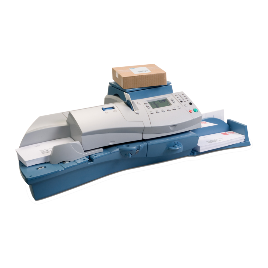
2 • Specifications 2.1 Product The DM300c, DM400c, and DM475 (all service installable) are desktop mailing systems designed for the global marketplace. They are fully com- Description pliant with all current postal standards for digital meters worldwide. These systems replace the following Pitney Bowes models: E510, E520, DP200, DP390, DM300, DM400, DM300i, DM400i, DM230L, DM300L, DM330L, DM350L, DM400L, Mega DM400, and DM450c. -
Page 16: Product Features
2 • Specifications 2.2 Product Both the DM300c (manual) and DM400c/DM475 (automatic feeder) ver- sions have the same feature set. This includes: Features • Ease of use — no training necessary for basic user operation. • Customer accessible tape track for jam clearance. - Page 17 • a Internal LAN NOTE: Features and specifications are subject to change without notice. Some fea- tures may not be available in certain markets or immediately at the time of product launch. DM300c/DM400c/DM475 Service Manual (SV61801 Rev. D)
-
Page 18: Material Spectrum
2 • Specifications 2.3 Material Material Spectrum The table below shows a range of materials suitable for use in DM300c/ Specifications DM400c/DM475 mailing machines. This is a partial listing. Type Source Regular white wove, 24 lb., Dependable, 24 # White Wove, No.10 low ink absorbing Regular white wove, 24 lb.,... -
Page 19: Envelope Size
Throughput: 65 tapes/minute. At least 50 consecutive tapes without interruption. Stack Height and Weight Stack Height 19 mm (0.75 inch) fl at mail, 76.2 mm (3 inches) letter mail Stack Weight 907.8 grams (2 lbs.) DM300c/DM400c/DM475 Service Manual (SV61801 Rev. D) -
Page 20: Envelope Flaps
For envelopes with a flap length from 25 to 60mm (1 to 2.36 inches), the minimum flap angle is 18 degrees. • For envelopes with a flap length greater than 60mm to the maximum flap length for the particular model, the minimum flap angle is 21 degrees. DM300c/DM400c/DM475 Service Manual (SV61801 Rev. D) -
Page 21: Ink Capacities, Consumption And Cartridge Life
64.1 lbs (29 kg ) without weighing platform (scale) 67.0 lbs. (30.4 kg) with weighing platform (scale) Acoustic Noise Level Operating <=6.5 BEL (A) re 1 pW Idle 5.5 BEL (A) re 1 pW DM300c/DM400c/DM475 Service Manual (SV61801 Rev. D) -
Page 22: General Machine Specifications
95 letters per minute DM475 - up to 120 letters per minute - up to 80 letters per minute in WOW mode Average 33 pieces (DM300c), 88 pieces (DM400c/DM450c/DM475), 260 days per Usage year per Day Average 8580 cycles (DM300c), 22,880 cycles (DM400c/DM450c/DM475), 260 days... -
Page 23: User Interface Controller
One RJ-11 port Modem Internal socket modem NOTE: The mailing system can support only one weighing platform at a time. It will not support both an integrated weighing platform and an external weighing platform simultaneously. DM300c/DM400c/DM475 Service Manual (SV61801 Rev. D) -
Page 24: Postage Meter
24 hours) Humidity 5% minimum, 100% maximum 85°F (29°C) NOTE: The operating environment is specified as a room ambient condition. The internal temperature should not exceed this temperature by more than 5°C. 2-10 DM300c/DM400c/DM475 Service Manual (SV61801 Rev. D) -
Page 25: Regulatory
CSA Certified or CUL R/C, rated 120Vac, 60Hz. Europe VDE-GS, TUV Rheinland-GS Registered or UL-DE-GS, rated 220- 240Vac, 50 Hz. CB Scheme Certificate and Test Report with U.K., Ger- many and Nordic deviations met as a minimum. DM300c/DM400c/DM475 Service Manual (SV61801 Rev. D) 2-11... -
Page 26: Weighing Options
Four Ad Bundle Four Inscription Bundle Town Circle 2.11 Internal Ad Up to 20 (10 installed at time of manufacture) and Inscription Inscriptions Up to 20 (12 installed at time of manufacture) Storage 2-12 DM300c/DM400c/DM475 Service Manual (SV61801 Rev. D) -
Page 27: Compatible Pitney Bowes Software
Print Head Replaceable • Ink Cartridge Parts • DM 300c Moistener Assembly • DM 400c Moistener Assembly • DM 475c Moistener Assembly • Water Bottle Assembly (DM400c/DM475) • Integrated Weighing Platform • Waste Tank DM300c/DM400c/DM475 Service Manual (SV61801 Rev. D) 2-13... -
Page 28: Meter Reports
This report provides system software version information. 0011969 Rate Mgr. #: 03.10 PBP Serial #: PCN: 0000 Platform: B0.02 UIC Software Version: 01.02.0042 PHS: 01.01.0014 Print Mgr.: 0118.0004 Feeder Ver.: Low Sector: 01.06.11 Feeder Profile: Protected Sector: 01.09.14 2-14 DM300c/DM400c/DM475 Service Manual (SV61801 Rev. D) -
Page 29: Configuration Report
The Account List Report lists the names and numbers of all accounts that are set up in your machine (if the Departmental Accounting feature is set up on your system). It must be printed on an attached printer. DM300c/DM400c/DM475 Service Manual (SV61801 Rev. D) 2-15... - Page 30 Serial Numbers • Software Versions • Funds and Piece Information • Warning Values • Time Settings • Advertisements • Inscriptions • Accounting Set Up • Modem Set Up • Scale Settings • Presets 2-16 DM300c/DM400c/DM475 Service Manual (SV61801 Rev. D)
-
Page 31: Introduction
3 • Theory This chapter explains how the DM300c/DM400c/DM475 mailing systems 3.1 Introduction work. It includes descriptions and explanations of the user interface, tape and envelope transport mechanisms, motion control system, print engine and electronics. 3.2 Product The products are designed for the small office and home markets with low- to mid-mailing volume applications. -
Page 32: User Interface
All models are equipped with a fixed (non-user removable) Intellilink™ control center. The user interface includes a seven-line monochrome LCD Interface display (DM300c/DM400c) or an eight-line color LCD display (DM475), an integrated full QWERTY keyboard, a numeric keypad, dedicated function keys and software-defined “soft” keys. -
Page 33: Modes Of Operation
It allows a customer service representative to perform main- tenance, test, and diagnostic functions and adjust certain parameters. See Chapter 6 for an explanation of the options available under the Service Menu. DM300c/DM400c/DM475 Service Manual (SV61801 Rev. D) -
Page 34: Envelope Tape Transport
Modes of Operation (cont’d) 3.3 User Setup. Users view and customize system settings, as explained in the Interface DM300c/DM400c/DM475 Operating Guide. These system settings include: 1. Date / Ad / Inscriptions Menu 2. Options Menu 3. Reports Menu 4. Presets (Normal and Custom) Menu 5. - Page 35 NOTE 2: Stack weight must not exceed two pounds or three inches in height (capacity of stacker), other- Figure 3-3D Feed Deck, Underside, Show- wise belt skipping and misfeeds will ing Drive Components occur. DM300c/DM400c/DM475 Service Manual (SV61801 Rev. D)
- Page 36 Chapter 5 of this manual. The operator can raise the entire upper transport to clear jams using the auto feeder’s jam release lever. DM300c/DM400c/DM475 Service Manual (SV61801 Rev. D)
- Page 37 It connects to the feeder PCB through J307 (DM400c/DM450c). The motion control system continuously monitors the state of sensors FS2 (auto feeder) and PS1 (printer) to flag error conditions and report them to the operator. DM300c/DM400c/DM475 Service Manual (SV61801 Rev. D)
-
Page 38: Tape Feeder
The tape motor is connected to J117 on the main logic board. DM300c/DM400c/DM475 Service Manual (SV61801 Rev. D) -
Page 39: Upper Transport
The idlers of the lower transport are Drive Shaft friction-driven by the feed components of the upper transport. See Figure 3-6, Drive Pulley right. for Segmented Feed Roller Figure 3-6 Upper Transport Feed Belt DM300c/DM400c/DM475 Service Manual (SV61801 Rev. D) -
Page 40: Lower Transport
DM300c) shows how the jam lever, lower transport cover and transport mechanism go togeth- Figure 3-9 Lower Transport Jam Lever, Cover er. The sensor board connects and Transport to the main logic board at J119. 3-10 DM300c/DM400c/DM475 Service Manual (SV61801 Rev. D) -
Page 41: Sequence Of Operation
Detect feed failures, jams and skew conditions and set the appropriate error flag; • Trigger the meter debit process; • Initiate printing; • Repeat the process or return the print carriage to the home position. DM300c/DM400c/DM475 Service Manual (SV61801 Rev. D) 3-11... - Page 42 (see Figure 3-12). It detects the lead edge of the mailpiece and initiates movement of the print carriage assembly from the home to the print position. (The carriage is home when the carriage home sensor is blocked). 3-12 DM300c/DM400c/DM475 Service Manual (SV61801 Rev. D)
- Page 43 The carriage drive motor then moves the carriage from the home position (unblocking the carriage home sensor). The print head is wiped and a mild purge initiated if necessary. DM300c/DM400c/DM475 Service Manual (SV61801 Rev. D) 3-13...
- Page 44 Figure 3-17, the system logic allows a time window of 110/120 msec or roughly three inches of paper travel for the debit process to complete successfully. If it fails, the meter is not debited, printing is in- hibited and a fault declared. 3-14 DM300c/DM400c/DM475 Service Manual (SV61801 Rev. D)
- Page 45 3 • Theory Of Operation 3.4 Envelope/ Sequence of Operation (cont’d) Tape Transport ✍ TIP: See section 3.10 for DM475 differences and specific theory. Figure 3-15 Transport Timing Diagram — DM400c/DM450c DM300c/DM400c/DM475 Service Manual (SV61801 Rev. D) 3-15...
- Page 46 Envelope arrives at print finish position -> Printing done Separate Roller Output Roller Input Roller Detect front of envelope by PS3 -> Envelope skew check Separate Roller Output Roller Input Roller above Figure 3-16 DM400c/DM450c Envelope Print Sequence 3-16 DM300c/DM400c/DM475 Service Manual (SV61801 Rev. D)
- Page 47 7. As the leading piece exits, the following piece blocks sensors PS1, PS2 and PS3, at which point the system logic assumes there is no transport fault (misfeed, jam or skew) and initiates the meter debit. The process repeats (steps 4 through 7) as required. DM300c/DM400c/DM475 Service Manual (SV61801 Rev. D) 3-17...
- Page 48 Transport Timing Diagram (Figure 3-18) below and the DM300c Enve- lope Print Diagram (Figure 3-19) on the following page. The operating sequence for the DM300c is essentially the same as that for the DM400c, with the obvious difference that the autofeeder, and therefore sensors FS1 and FS2 are not present.
- Page 49 Output Roller Input Roller Detect front of envelope by PS3 -> Stop transport motor -> Envelope skew check -> Start data generate previous page Output Roller Input Roller Figure 3-19 DM300c Envelope Print Sequence DM300c/DM400c/DM475 Service Manual (SV61801 Rev. D) 3-19...
- Page 50 When the tape lead edge is 30 mm beyond PS1, the system logic stops the tape motor and the process re- peats from step 4 to 9. 3-20 DM300c/DM400c/DM475 Service Manual (SV61801 Rev. D)
- Page 51 Detect front of envelope by PS3 -> Stop transport motor -> Check envelope -> tape skew Start data generate Data generate complete -> Start transport motor Envelope arrives at print start position -> Printing start Figure 3-20 A Tape Print Sequence DM300c/DM400c/DM475 Service Manual (SV61801 Rev. D) 3-21...
- Page 52 Envelope arrives at print finish position -> Printing complete Tape arrives at print fi nish position -> Printing complete PS1+30[mm] -> Stop tape motor To continue sequence, go to 4 on previous page Figure 3-20 B Tape Print Sequence 3-22 DM300c/DM400c/DM475 Service Manual (SV61801 Rev. D)
-
Page 53: Ink System
The system displays a low ink warning when approxi- mately 500 prints are left. For the DM300c, a low ink condition is defi ned as 5,300 pieces, and for the DM400c/DM475, 8,300 pieces. The following error messages are associated with the ink tank: Ink Tank Fault—Power cycle;... -
Page 54: Print Head And Carriage Board
The print head is unique to the DM300/400c. It is not an off-the-shelf item. • The print head does not use a standard connec- tion mechanism. Figure 3-23 Print Head — Contact View 3-24 DM300c/DM400c/DM475 Service Manual (SV61801 Rev. D) -
Page 55: Carriage Assembly
2.2 lbs. Bottom View As explained below, the home position is detected by a sensor mounted on the purge unit. The car- riage drive motor connects to the main logic board at J118. DM300c/DM400c/DM475 Service Manual (SV61801 Rev. D) 3-25... -
Page 56: Purge Unit
Capping Station. The print head cap keeps the print head nozzles from drying out. The print head is capped when the car- riage assembly is in the Figure 3-28 Purge Unit PCB home position. 3-26 DM300c/DM400c/DM475 Service Manual (SV61801 Rev. D) - Page 57 • Following a jam or shut down; • Before, during and after printing. The purge cycles are listed on the next page. The purge unit is connected to the main logic board at J120 (yellow) and J116 (purple). DM300c/DM400c/DM475 Service Manual (SV61801 Rev. D) 3-27...
-
Page 58: Ink System
Spits: 100 dots per nozzle Purge E-3 (While Printing Purge) Spits: 30 dots per nozzle Interval: every 30 seconds during the print Spits area: print position NOTE: This purge sequence does not interrupt printing. 3-28 DM300c/DM400c/DM475 Service Manual (SV61801 Rev. D) -
Page 59: Waste Tank
Figure 3-30 Test Patterns Note that printer maintenance options are also available in the Service Menu as explained in Chapter 6 - Service Menu. DM300c/DM400c/DM475 Service Manual (SV61801 Rev. D) 3-29... -
Page 60: Electronics
Tank EEROM Feeder Control Motion Control (DM400c Only) Processor H8S/2212 Feeder Motor (Servo) On-Chip Memory Feeder Sensor FS1 12K RAM 128K Flash Feeder Sensor FS2 Feeder Encoder Figure 3-31 System Architecture Block Diagram (DM300c/DM400c/DM450c) 3-30 DM300c/DM400c/DM475 Service Manual (SV61801 Rev. D) - Page 61 Feeder Encoder 1. The system is designed to handle different types of PSDs. 2. The DM300c and DM400c/DM450c use the same main logic board but each PCN (G900, G903, G905) will have a unique part number for their Feeder Motor replacement main logic boards installed by service.
- Page 62 Transport Motor Encoder WOW Mid Sensor Power +5V/+27V WOW Exit Sensor Thickness Encoder Tedea #1041 Load Cell Inst AMP & AD(20bit) AD620, & AD7703 DW84009 Figure 3-32 B System Architecture Block Diagram (DM475) 3-32 DM300c/DM400c/DM475 Service Manual (SV61801 Rev. D)
-
Page 63: Pcbs
Connector J126 is also used for the detection of the power supply type to ensure that DM400c units are fitted with the higher voltage power supply units. DM300c/DM400c/DM475 Service Manual (SV61801 Rev. D) 3-33... - Page 64 PSD/iButton hardware. J123 J125 PS J115 Transport Motor J101 MODEM NVRAM Battery under Modem Card J128 Figure 3-35 B Controller (Main Logic) Board NOTE: Boards may vary; some connectors are not used 3-34 DM300c/DM400c/DM475 Service Manual (SV61801 Rev. D)
- Page 65 The DM300c and DM400c use the same main logic board, but each meter PCN (G900, G903, G905) will have a unique part number. This is due to the fact that the main board must have the correct PCN-specific application code on it prior to installation.
- Page 66 IntelliLink™ and the Pitney Bowes Data Center. The board contains all modem-related components. An RJ11 jack is mounted on the main logic board at J108. Figure 3-36 Modem Board 3-36 DM300c/DM400c/DM475 Service Manual (SV61801 Rev. D)
- Page 67 7-pin FFC to the carriage board feeder. PCB. Tank PSoC LFSR EEPROM UART Carriage Board Print head EEPROM Figure 3-37 Carriage Board, Print Head and Ink Cartridge Block Diagram DM300c/DM400c/DM475 Service Manual (SV61801 Rev. D) 3-37...
- Page 68 J120. NOTE: These contacts MUST be free of ink contamination Figure 3-38 Location of Print Head Figure 3-39 Print Head Contacts Controller (Carriage) Board Figure 3-40 Purge Unit Junction Board 3-38 DM300c/DM400c/DM475 Service Manual (SV61801 Rev. D)
- Page 69 J311 and J301. The feeder logic board is connected to the pow- er supply unit through connector J303. The feeder logic board monitors the state transitions of transport sensor PS1 in the mailing machine transport. Figure 3-41 A Feeder Logic Board (DM400c/DM450c) DM300c/DM400c/DM475 Service Manual (SV61801 Rev. D) 3-39...
- Page 70 J16 to WOW Thickness Encoder J10 to Feeder/ J17 (Not Used) WOW board J19 to WOW Motor J20 3rd Width Sensor J22 1st Width Sensor J21 2nd Width Sensor Figure 3-41C Feeder/WOW Junction PCB (DM475) 3-40 DM300c/DM400c/DM475 Service Manual (SV61801 Rev. D)
-
Page 71: Sensor Summary
Ink Cartridge Cover Sensor. This sensor serves as an interlock device that detects whether the top cover is open or closed. It is connected to the main logic board through J121. The system will not operate with the top cover open. DM300c/DM400c/DM475 Service Manual (SV61801 Rev. D) 3-41... - Page 72 This sensor also de- tects jams in the paper path. It connects to the feeder PCB through J307 for DM400c/DM450c or through J315 on the feeder/WOW for the DM475. 3-42 DM300c/DM400c/DM475 Service Manual (SV61801 Rev. D)
-
Page 73: Motor Summary
3.5.4 for more details. The purge motor is a stepper type driven by discrete switches from the main logic board to which it is connected through J116. The motor drive is protected by a 1.0A non-replaceable fuse. DM300c/DM400c/DM475 Service Manual (SV61801 Rev. D) 3-43... -
Page 74: Scale Controller
2. LED (green) - “Heartbeat” flashing once per second. It indicates that 5V is present on the main logic board and that the microprocessor is running. 1. LED (dim red) – future use. 3-44 DM300c/DM400c/DM475 Service Manual (SV61801 Rev. D) - Page 75 WOW units used on other mailing machines (DM800i, DM1000, etc.) have belts that drive the media from above. The DM475, however, has a new WOW design that uses a drive belt below the media, and the idler rollers above. DM300c/DM400c/DM475 Service Manual (SV61801 Rev. D) 3-45...
- Page 76 3 • Theory Of Operation 3.10 DM475 Feeder/WOW Theory Figure 3-43 Block Diagram (DM475) 3-46 DM300c/DM400c/DM475 Service Manual (SV61801 Rev. D)
- Page 77 WOW and printer are run at different speeds in order to control the gap between media and insure one piece on the WOW at a time. For example: Feeder: 23.5 ips (inches/sec), at TAR 2 WOW transport: 23.75 ips Printer transport: DM300c/DM400c/DM475 Service Manual (SV61801 Rev. D) 3-47...
- Page 78 • In WOW mode, the throughput will be defaulted to 80 LPM. Sensors and Actuators The following diagram illustrates the spacing of key sensors and rollers: DM475 Figure 3-44 Sensors and Actuators (DM475) 3-48 DM300c/DM400c/DM475 Service Manual (SV61801 Rev. D)
-
Page 79: Dm475 Feeder/Wow Theory
Detects mail entering the printer mod- Entrance ule. Skew Digital Through-Beam Used to detect skew in the DM300c. Skew sensing is turned off in the DM400 through DM475. Even though there is no S2 on the DM475, it is still displayed in Diagnostics as “Clear”. - Page 80 Brush DC and encoder and stop for weighing when necessary Printer Motor Transport mail at con- Brush DC and encoder stant speed for printing Tape Feed Feed tape at constant Stepper speed for printing 3-50 DM300c/DM400c/DM475 Service Manual (SV61801 Rev. D)
-
Page 81: Chapter 4 - Troubleshooting
4 • Troubleshooting/Diagnostics This chapter explains how to troubleshoot the DM300c/DM400c/DM450c/ DM475. It includes troubleshooting charts, and a list of error codes and their Introduction meanings. It also includes instructions for withdrawing the mailing machine from service. General Troubleshooting Chapter 3, Theory of Operation, contains valuable information that can help you analyze a problem and isolate the cause. - Page 82 If these errors display when the jam lever is Check sensor board and wiring to Main Logic Open” and 2/2 closed and the transport is clear, the sensor Board, J119. “Clear Transport” board may be suspect. errors display. DM300c/DM400c/DM475 Service Manual (SV61801 Rev. D)
-
Page 83: Keyboard And Display Faults
See Table 4-1 for power ON an initialization faults. Display does not Meter appears to be “stuck” on the same dis- Power cycle the meter to reboot and start over. change. play for an extended period of time. DM300c/DM400c/DM475 Service Manual (SV61801 Rev. D) - Page 84 Machine fails Wrong power supply Installed. Verify that the correct power supply is installed. to recognize The DM300c, DM400c/DM450c, and DM475 all automatic feeder. use a different power supply. Loose connection between Base and Feeder. Check the communication cables between the meter and the automatic feeder.
-
Page 85: Mailing Machine Transport Faults
Drive belts damaged or improperly tensioned. Check drive belts and tensioners. Segmented Transport Drive Transport Transport Roller Belt Drive Motor Drive Belts and Tensioners Pulley Bearing Drive Shaft Lower Transport Idlers Pulley Figure 4-1 Transport Drive DM300c/DM400c/DM475 Service Manual (SV61801 Rev. D) - Page 86 If oversized mail piece, use a tape strip. No printing Envelope blank, no errors. Check ink cartridge. Perform purge. Clean elec- occurs. trical connections; check electrical connections. DM300c/DM400c/DM475 Service Manual (SV61801 Rev. D)
- Page 87 Main Logic Board, J122. Last few tapes Tape pressure plate may be hung up on bezel. Make sure pressure plate is not binding. fail to feed. Gear Train Tape Motor Tape Drive Roller Figure 4-2 Tape Drive DM300c/DM400c/DM475 Service Manual (SV61801 Rev. D)
- Page 88 Wrong ink cartridge installed. Defective car- The DM100i cartridge will fit into the error message. tridge. DM300c/400c print carriage but will not work. Check the cartridge. It sometimes happens that customers are sent the wrong cartridge. DM300c/DM400c/DM475 Service Manual (SV61801 Rev. D)
- Page 89 Wiper and/or capping station may be contami- Clean wiper and capping station. Perform a “C” nated with excess ink. Purge may be required. purge, then a “D” purge. DM300c/DM400c/DM475 Service Manual (SV61801 Rev. D)
- Page 90 Most ink is used for maintenance. Empty cartridge = 40 grams (technically there is still some left to insure it does not run dry and allow air into system). 35 grams is really empty. 4-10 DM300c/DM400c/DM475 Service Manual (SV61801 Rev. D)
- Page 91 Reboot. Check PH ribbon cable and connection at J127. Print head itself may be bad If, after trying all of the above there is still no detection, replace print head. DM300c/DM400c/DM475 Service Manual (SV61801 Rev. D) 4-11...
-
Page 92: Print Carriage Faults
System may lock when error is cleared. Use service diagnostics to check. Also check wiring to Main Logic Board, J116. In addition, check purge motor and wir- ing to Main Logic Board, J120. 4-12 DM300c/DM400c/DM475 Service Manual (SV61801 Rev. D) - Page 93 Use Tefl on/silicone grease on feeder gear shafts if there is noise. Also use on white tension idler rollers if they make a high squealing noise. Meter Hangs. Laser printer has lost its enumeration. DM300c/DM400c/DM475 Service Manual (SV61801 Rev. D) 4-13...
-
Page 94: Modem/Connection Faults
Type the area code in the “Area Code” field and then select “X2/V.90” under the pull down menu for the “Line Type”. Click on “Get Numbers”. Choose a local number and pro- gram it into the unit. 4-14 DM300c/DM400c/DM475 Service Manual (SV61801 Rev. D) - Page 95 PbP number correct? Other modem parameters OK? Faulty modem. Check that modem is properly seated on main logic board and that connection between J2 on modem board and J109 on main logic board is sound. DM300c/DM400c/DM475 Service Manual (SV61801 Rev. D) 4-15...
-
Page 96: Integrated Scale Faults
Auto scale func- Auto scale may be turned off. Scale Enter menu and make sure auto scale function is ON. tion does not not set up properly. work. 4-16 DM300c/DM400c/DM475 Service Manual (SV61801 Rev. D) - Page 97 Code Listing Tables 4-13 through 4-21 list all codes, arranged by class. They may help you to isolate a problem further and provide helpful data should engineering analysis be required. DM300c/DM400c/DM475 Service Manual (SV61801 Rev. D) 4-17...
-
Page 98: Error Codes
• System stops when low ink msg is displayed 1600 • Run away transport Cycle power if necessary • Recoverable lockup 2000 Unknown Cycle power to recover 2003 and 2004 Startup error. Reboot system. 4-18 DM300c/DM400c/DM475 Service Manual (SV61801 Rev. D) - Page 99 2484 (Paper er- 1st piece hanging out of printer Verify mail piece and rerun through ma- ror) - print OK - 2nd piece following chine if necessary with small gap at printer DM300c/DM400c/DM475 Service Manual (SV61801 Rev. D) 4-19...
- Page 100 Try rebooting to clear mes- sage. If unable to clear message, print head is suspect. 24A4 or 24A5 Reboot. Leave system off for a minimum of one minute. A replacement print head will not resolve these errors. 4-20 DM300c/DM400c/DM475 Service Manual (SV61801 Rev. D)
- Page 101 • No print, funds not debited • Mail piece stopped, lead edge at WOW roller 3 • Jam at transport sealer roller 248B (Jam) Tape Jammed Jam in tape feeder Clear jam. Clear Printer Trans- port. DM300c/DM400c/DM475 Service Manual (SV61801 Rev. D) 4-21...
- Page 102 • Piece jammed at stripper blade • No apparent jam • Fail to feed, no jam tray 1/2 full • Piece hanging at printer, no jam, print OK 372A Feeder error with C4 envelope. Clear jam. 4-22 DM300c/DM400c/DM475 Service Manual (SV61801 Rev. D)
- Page 103 In WOW modes, not allows system to restart if WOW is not cleared. If WS2 is not blocked, the WOW will likely throw a re- zero error if material is still on the WOW transport. DM300c/DM400c/DM475 Service Manual (SV61801 Rev. D) 4-23...
- Page 104 FS2/WS1. 373E (Stream WOW Error • Streamfeed Clear jam. feed) Clear WOW Transport. • Dimension rating error dis- played 378E (Feeder/ WOW Error Clear jam. WOW error) Clear WOW Transport. 4-24 DM300c/DM400c/DM475 Service Manual (SV61801 Rev. D)
- Page 105 37AD (Feeder WOW Error Clear jam. error) Clear WOW Transport. 37AF (WOW Mailpiece Too Heavy Clear jam. error) Clear WOW Transport. 37B0 (WOW WOW Error Clear jam. error) Clear WOW Transport. DM300c/DM400c/DM475 Service Manual (SV61801 Rev. D) 4-25...
- Page 106 • Streamfeed 4000 • Unknown Clear jam. • Jam on printer frame 4500 • Unknown Clear jam. • Piece jammed at stripper blade 4600 • Unknown • Noise heard in WOW (click- ing) 4-26 DM300c/DM400c/DM475 Service Manual (SV61801 Rev. D)
- Page 107 1. Press CLEAR. Password 2. Reboot for 30 seconds. 3. If the display returns to ENTER AMOUNT TO ADD TO METER, press CLEAR. 4. Select RETURN TO START to begin the install over again. DM300c/DM400c/DM475 Service Manual (SV61801 Rev. D) 4-27...
- Page 108 • Stream feed, mail piece un- derneath not printed on • WOW registration wall not aligned with feeder wall Print Head/Ink See Table 4-6. Tank not Detected Rate Manager Not See Table 4-11. Initialized 4-28 DM300c/DM400c/DM475 Service Manual (SV61801 Rev. D)
- Page 109 WOW trans- port. When piece from WOW is cleared, allow user to restart with material upstream of WOW. Weight Over Ca- See Table 4-11. pacity DM300c/DM400c/DM475 Service Manual (SV61801 Rev. D) 4-29...
- Page 110 Date of Mailing OR current date is later than Watchdog Time, createIndicium or commit msg. 2020 IPSD is in the tampered state and must be returned to Dallas. 2021 Failure in either commitTransaction or CreateIndicium 4-30 DM300c/DM400c/DM475 Service Manual (SV61801 Rev. D)
- Page 111 IPSD Ring self-tests failed. 2108 IPSD Ring self-tests failed. 2109 IPSD SHA1 self-tests failed. 210A IPSD DES self-tests failed. 210B IPSD DSA self-tests failed. 210C IPSD ECDSA self-tests failed. 210D IPSD SHA1MAC self-tests failed. DM300c/DM400c/DM475 Service Manual (SV61801 Rev. D) 4-31...
-
Page 112: Image Generator Errors (22Xx)
A register group has a field size that is too big OR the number of VCR definitions for a graphic doesn’t match the sum of all the register field lengths for the graphic OR the total number of VCRs for a region map is more than the max allowed. 4-32 DM300c/DM400c/DM475 Service Manual (SV61801 Rev. D) -
Page 113: Barcode Generator Errors (22Xx)
The amount of data for the 1D barcode is more bytes than will fit in the work buffer 2253 The 1D barcode data contains characters that aren’t supported by the Code 39 character set. DM300c/DM400c/DM475 Service Manual (SV61801 Rev. D) 4-33... -
Page 114: Print Head Security Errors (23Xx)
A random number from the PH PSOC was one of the restricted values 230A A random number from the PH PSOC is the same as the last random number from the PH PSOC 4-34 DM300c/DM400c/DM475 Service Manual (SV61801 Rev. D) -
Page 115: Print Manager Errors (24Xx)
24A4 Printhead temperature out of range 24A5 Printhead heater failure 24B1 E_MSG_SRC 24B2 E_MSG_DEST 24B3 E_MSG_ID 24B4 E_MSG_TYPE 24B5 E_MSG_PARAMETER 24B6 E_MSG_NA (Not appropriate message, like “Perform Printer Maintenance” in Seal Only Mode) DM300c/DM400c/DM475 Service Manual (SV61801 Rev. D) 4-35... -
Page 116: Bob" Task Errors (25Xx)
2523 Town circle not found in flash 2524 Town circle font not found in flash 2525 Error reading UIC date or time 2526 Error building a device message 2527 Erroneous message script ID 4-36 DM300c/DM400c/DM475 Service Manual (SV61801 Rev. D) - Page 117 Error accessing a date time graphic 254B Error setting permit batch count index 254C Error finding an auto inscription in flash 254D Auto inscription ID is not in range 254E Piece count end of life error DM300c/DM400c/DM475 Service Manual (SV61801 Rev. D) 4-37...
- Page 118 Unrecognized Family code, or family code = Gemini, but MicroStatus String is not as expeccted. 2561 Attempt to disable the bootloader (or set security lock) before entering and testing the APP mode. 2562 EDM trying to passthrough msg to IPSD BL, bob can’t talk to IPSD. 4-38 DM300c/DM400c/DM475 Service Manual (SV61801 Rev. D)
-
Page 119: Wow Motion Control Processor (Mcp) Error Codes (2Axx)
The Feeder Motor Thermister is not operating properly. Indicates an error with the thermister. Check the thermister and the feeder board. 37BC The Feeder Motor Temperature has risen too high and the system must not run mail. Stop processing mail and allow the Feeder Motor to cool down. DM300c/DM400c/DM475 Service Manual (SV61801 Rev. D) 4-39... -
Page 120: Cleaning The Print Head And Related Surfaces
Always use a new cleaning swab to avoid permanent damage on the print head surface (discard after use). Also, the cleaning swab should be used to wipe in one direction only. Print Head Surface Cleaning Swab 4-40 DM300c/DM400c/DM475 Service Manual (SV61801 Rev. D) - Page 121 Purge Clean ink on Unit Cap edges 6. Reinstall print head. From the Service Menu, select Diagnostics>PM Maintenance>Print Test Pattern, and/or run some sample mail pieces through the machine to confirm proper printing. DM300c/DM400c/DM475 Service Manual (SV61801 Rev. D) 4-41...
-
Page 122: Scenarios
The G900/G905 iButton PSD is a rented item and must be returned to Pitney Bowes Meter Re- turns as per USPS Postage Meter requirements. Follow the procedures on the subsequent pages. 4-42 DM300c/DM400c/DM475 Service Manual (SV61801 Rev. D) -
Page 123: Removal Of Ibutton Psd
Attach the handle of the iButton PSD to the cover using the provided screw. (See Figure 4-8.) NOTE: Instructions are not sent with the Return kit because we do not want the customer to find them and try to remove the iButton! DM300c/DM400c/DM475 Service Manual (SV61801 Rev. D) 4-43... -
Page 124: Running Meter Withdrawal From Menu
Used: $000 . 000 Batch Count: DEC 08 03 5 : 31P Available: $000 . 000 Batch Value: $000 . 000 Total Pieces: 0 PBP Serial No.: 0011969 Control Sum: $000 . 000 4-44 DM300c/DM400c/DM475 Service Manual (SV61801 Rev. D) -
Page 125: Withdrawal Process
Postage by Phone® Account, but they want to keep their ma- chine base. The “Box It” process (used by DM100i/DM200L) will be used for DM300c/ DM400c/DM475. The customer will be shipped a box (Sales Kit 3C00104 or 4C00104) with instructions explaining how to transfer their funds back to their Postage By Phone®... -
Page 126: Completing The 3601C
6. You and the customer must sign the 3601C form confirming that the transaction is completed. 7. If QAR, apply the pink label to ICC case and return ICC/PSD to New- town2 via registered USPS priority mail along with all required copies of Form 3601C. 4-46 DM300c/DM400c/DM475 Service Manual (SV61801 Rev. D) -
Page 127: Introduction
#2 Phillips head screwdriver with at least an 8” shank and a magnetic tip • Flat blade screwdriver Printer/Base (use for all models) (photos show DM300c but procedures apply to all models) 5.2 Back Cover ................5-3 5.3 Control Panel ................5-3 5.4 Front Sub-Panel ................ 5-4 5.5 Control Panel Ribbon Cables ........... - Page 128 5.52 WOW Transport Motor............5-58 5.53 Lower WOW Transport Assembly (as a whole unit) ....5-60 5.54 Lower WOW Transport Components........5-62 5.55 WOW Load Cell Assembly ............ 5-64 5.56 Feeder/WOW Registration Wall Alignment ......5-66 DM300c/DM400c/DM475 Service Manual (SV61801 Rev. D)
-
Page 129: Back Cover
PCB to free it from the base. The control panel and cover are replaceable as a sin- gle unit (Figures 5-5, 5-6, 5-7). Figure 5-4B Control Panel Screws DM300c/DM400c/DM475 Service Manual (SV61801 Rev. D) -
Page 130: Control Panel Ribbon Cables
(figure, right). 5. Remove the two harness con- nectors from the board. Figure 5-10 Control Panel Harness 6. Reassemble in reverse order. Connections at Main Logic Board DM300c/DM400c/DM475 Service Manual (SV61801 Rev. D) -
Page 131: Bottom Cover (Base Pan) And Side Deck Guide
(section 5.6). 2. Remove three screws that se- cure deck to frame. See Figures 5-12 and 5-13B for screw loca- tions. 3. Reassemble in reverse order. Figure 5-13B Side Deck Mounting Screws DM300c/DM400c/DM475 Service Manual (SV61801 Rev. D) -
Page 132: Main Transport Feed Belt
7. Make sure belt tracks properly. 8. Close lower transport and test for proper operation. 9. Reassemble in reverse order. Roller grooves Figure 5-14 Removing Transport Drive Figure 5-15 Transport Belt Removed. Belt Note Grooves in Rollers. DM300c/DM400c/DM475 Service Manual (SV61801 Rev. D) -
Page 133: Purge Unit
3. Remove two board mounting screws, figure, right. 4. Carefully disconnect harness Figure 5-17B Sensor Board Cover connector to free board. See Fig- Removed ure 5-17C, next page. 5. Reassemble in reverse order. DM300c/DM400c/DM475 Service Manual (SV61801 Rev. D) -
Page 134: Purge Unit Motor And Gears
(Figure 5-20). Remove belt as shown (Figure 5-21). 6. Hold motor from underside of machine. While holding motor, remove two screws as shown to free it (Figure 5-22). 7. Reassemble in reverse order. DM300c/DM400c/DM475 Service Manual (SV61801 Rev. D) - Page 135 Main Logic Board Figure 5-20 Loosen Belt Tensioner Figure 5-21 Remove Belt from Drive Slightly; Tighten in UP position. Pulley Figure 5-22 Remove Two Motor Mount- Figure 5-23 Transport Drive Motor ing Screws DM300c/DM400c/DM475 Service Manual (SV61801 Rev. D)
-
Page 136: Carriage Drive Motor
Figure 5-24 Disconnect Harnesses and Figure 5-25 Let Wire Loom Hang; Unscrew Wire Loom Unscrew Two Motor Mounting Screws Figure 5-26 Remove Motor and Bracket Assembly; Remove Carriage Drive Belt Figure 5-27 Remove Motor from Bracket Assembly 5-10 DM300c/DM400c/DM475 Service Manual (SV61801 Rev. D) -
Page 137: Rear Drive Belts
4. Replace belt. 5. Loosen belt tensioner. Allow spring to normalize tension on belt. DO NOT apply additional Figure 5-30 Remove Intermediate Drive tension. Belt 6. Tighten belt tensioner. 7. Reassemble in reverse order. DM300c/DM400c/DM475 Service Manual (SV61801 Rev. D) 5-11... -
Page 138: Carriage Drive Belt
Figure 5-31. Figure 5-32 Carriage Belt Loop 2. Connect a spring gauge to the adjust- ment bracket and set the belt tension for 1 kg (2.2 lbs.) +/- 10%. 3. Tighten adjustment screw. 5-12 DM300c/DM400c/DM475 Service Manual (SV61801 Rev. D) -
Page 139: Print Head Carriage Assembly
Figure 5-37 Turn Gear Clockwise until keeper. Pull out slightly on bottom Printhead Lock and Wiper are Fully DOWN tab. To free keeper, pull it carefully towards front of machine. See Fig- ure 5-39, next page. DM300c/DM400c/DM475 Service Manual (SV61801 Rev. D) 5-13... - Page 140 (Figure 5-42 and 5-43). 13. As the shaft is released from both ends, push it toward the center of the machine to free it from the print carriage. (The shaft will snap out of position.) 5-14 DM300c/DM400c/DM475 Service Manual (SV61801 Rev. D)
-
Page 141: Drive Shaft
Figure 5-45 Removing Carriage Assem- Power Supply Shield Logic Board Inner Rail Bushing Drive Shaft Snaps in Position Purge Unit Drive Motor Figure 5-46 Chassis with Carriage As- Figure 5-47 Carriage Assembly sembly Removed DM300c/DM400c/DM475 Service Manual (SV61801 Rev. D) 5-15... - Page 142 6. Reassemble in reverse order. Figure 5-48 Removing Drive Shaft Gear Figure 5-49 Removing Drive Shaft Rear Bearing Bearing Tabs Groove Figure 5-50 Disengaging Roller from Figure 5-51 Drive Shaft Components Drive Shaft Groove 5-16 DM300c/DM400c/DM475 Service Manual (SV61801 Rev. D)
-
Page 143: Tape Feed Unit
1. Remove tape feeder unit as described above (section 5.15). 2. Remove E-Clip and bearing from roller shaft. See Figure 5-55, above right. 3. Free roller assembly from tape feed housing. 4. Reassemble in reverse order. DM300c/DM400c/DM475 Service Manual (SV61801 Rev. D) 5-17... -
Page 144: Postal Security Device (Psd)
Remove the iButton PSD and tighten both the inner and outer connector tangs. Pull the inner connector tang to bend it outward. Push the outer connector tang toward the PC board. Then reinstall the iButton PSD. 5-18 DM300c/DM400c/DM475 Service Manual (SV61801 Rev. D) -
Page 145: Main Logic Board
DLA. Then connect using “Check PBP Balance” via the Refill Postage key or by selecting “Check For Updates” from the Data Center Options menu. DM300c/DM400c/DM475 Service Manual (SV61801 Rev. D) 5-19... -
Page 146: Modem Board
4. Disconnect wiring harness from board to free it. 5. Reassemble in reverse order. Make sure wiring is not subject to crimping or extreme bends. Figure 5-61 Removing Modem Board Figure 5-62 Modem Board, Component Side 5-20 DM300c/DM400c/DM475 Service Manual (SV61801 Rev. D) -
Page 147: Power Supply
6. Remove two screws securing power supply shield. 7. Remove board and shield from machine. 8. To remove board from shield, remove two screws as shown in Figure 5-64 above. 9. Reassemble in reverse order. DM300c/DM400c/DM475 Service Manual (SV61801 Rev. D) 5-21... -
Page 148: Encoder Sensor, Encoder Disc And Sensor Board
Sensor Board 7. Reassemble in reverse order. Figure 5-66 Removing Encoder Disc Figure 5-67 Removing Encoder Disc Cover Figure 5-68 Encoder Sensor, Encoder Figure 5-69 3C00, 4C00 5C00 Sensor Disc and Cover Board (Front) 5-22 DM300c/DM400c/DM475 Service Manual (SV61801 Rev. D) -
Page 149: Segmented Roller
6. Free segmented roller from frame and belt as shown in Figure 5-71. 7. Reassemble in reverse order. Input Feed Deck Front Apron Figure 5-70 Removing Input Feed Deck Figure 5-71 Removing Segmented and Front Apron Roller Assembly Figure 5-72 Segmented Roller Assembly DM300c/DM400c/DM475 Service Manual (SV61801 Rev. D) 5-23... -
Page 150: Lower Transport Assembly
Figure 5-73 Removing Right Pivot Stud Figure 5-74 Removing Left Pivot Stud Bracket Bracket Figure 5-75 Pivot Stud Bracket and Lower Transport Assembly Figure 5-76 Side and Top Views of Lower Transport Assembly 5-24 DM300c/DM400c/DM475 Service Manual (SV61801 Rev. D) -
Page 151: Lower Transport Cover
1. Squeeze tray handles and slide out waste pad tray. Replacement 2. Carefully lift out waste pad using a paper towel. 3. Replace waste pad and insert tray in side of machine. Figure 5-78 Waste Pad Drawer Figure 5-79 Removing Waste Pad DM300c/DM400c/DM475 Service Manual (SV61801 Rev. D) 5-25... -
Page 152: Auto-Feeder (Use For Dm400C/Dm450C/Dm475)
Feeder Upper Cover per cover. 4. Reassemble in reverse order. [DM475 - The left side screw is the ground for nudger deck back plate.] Figure 5-82 Mounting Screws 5-26 DM300c/DM400c/DM475 Service Manual (SV61801 Rev. D) -
Page 153: Side Guide
Figure 5-83 Removing Stepped Screw 3. Slide side guide to front and Side Guide remove it as shown in figure, right. 4. Reassemble in reverse order. Side Guide Slide Figure 5-84 Removing Side Guide DM300c/DM400c/DM475 Service Manual (SV61801 Rev. D) 5-27... -
Page 154: Feed Deck
Lift up front edge of deck and pull carefully toward front to free it. 6. Reassemble in reverse order. NOTE: Make sure you hold down the stacker sensor flag when replacing the deck as- sembly. 5-28 DM300c/DM400c/DM475 Service Manual (SV61801 Rev. D) -
Page 155: Feeder Unit
PCB: J309, J307, and J301 DM475 - Remove two screws for moistener deck (one is self-tapping in hole). 3. Remove feed deck (section 5.27). Figure 5-89 DM400c/DM450c Printer/Base Removed from Base Pan DM300c/DM400c/DM475 Service Manual (SV61801 Rev. D) 5-29... - Page 156 5.28 Feeder Unit in figure, right. Moistener Assembly Figure 5-90 Removing Moistener 5. Remove moistener tank. Moistener Tank and Wick Figure 5-91 Removing Moistener Tank Figure 5-92 A and B Removing Feed Unit Mounting Screws 5-30 DM300c/DM400c/DM475 Service Manual (SV61801 Rev. D)
-
Page 157: Feeder Pcb Assembly
PCB Assembly 2. Unplug five connectors (DM400c/ (arrows in figure, right) and DM450c) remove four screws to de- tach feeder PCB. 3. Reassemble in reverse order. Mounting Screws Figure 5-94 Removing Feeder PCB DM300c/DM400c/DM475 Service Manual (SV61801 Rev. D) 5-31... -
Page 158: Retard Roller
Figure 5-96 Removing Springs position when you reassem- ble the unit. CAUTION! Failure to do so will change the tension ap- plied to the pressure rollers and compromise feeding. 5-32 DM300c/DM400c/DM475 Service Manual (SV61801 Rev. D) - Page 159 5. Remove retard roller assem- bly as shown in figure, right. Retard Roller Assembly Figure 5-98 Retard Roller 6. Remove screw and cap. 7. Reassemble in reverse order. Screw Figure 5-99 Removing Screw and Cap DM300c/DM400c/DM475 Service Manual (SV61801 Rev. D) 5-33...
-
Page 160: Feed Roller Assembly
Release Lever Figure 5-102 Release Lever 6. Maneuver retard gap plate to free it, and slide to right side Retard Gap Plate to remove it. Figure 5-103 Retard Gap Plate 5-34 DM300c/DM400c/DM475 Service Manual (SV61801 Rev. D) - Page 161 CAUTION! Changing this set- ting will cause separation er- rors. Gap Cam Figure 5-107 Gap Cam Shown with Re- lease Holder in Place DM300c/DM400c/DM475 Service Manual (SV61801 Rev. D) 5-35...
-
Page 162: Feed Belt Assembly
Loosen Screw 5. Remove two E-Clips, and pulleys as shown at the right. Spring Timing Belt Figure 5-109 Timing Belt/Gear Removal 6. Remove three bushings as shown in Figure 5-110. Figure 5-110 Bushing Removal 5-36 DM300c/DM400c/DM475 Service Manual (SV61801 Rev. D) - Page 163 Figure 5-112 Screw Removal, Right 8. Push out the two bushings Roller Assemblies that confine roller shafts; then remove roller assemblies by lifting out of cutouts. E-Clips and Bushings Figure 5-113 Roller Plate Removal DM300c/DM400c/DM475 Service Manual (SV61801 Rev. D) 5-37...
-
Page 164: Feed Motor
1. Remove the feeder unit (sec- tion 5.28). 2. Disconnect connector (A), from feeder PCB and dis- mount the harness (B) from the three harness guides (C). 3. Reassemble in reverse order Figure 5-116 Disconnecting Harness 5-38 DM300c/DM400c/DM475 Service Manual (SV61801 Rev. D) -
Page 165: Feed Encoder
2. Unplug connector (A). 3. Remove screw (B), and detach encoder sensor (C). 4. Remove E-Clip and washer (D). 5. Remove feed encoder disc (E). 6. Reassemble in reverse order. Figure 5-119 Removing Encoder DM300c/DM400c/DM475 Service Manual (SV61801 Rev. D) 5-39... -
Page 166: Seal/No Seal Lever
1. Push cap assembly (figure, right) in. Seal Lever 2. Turn cap assembly one-quar- ter turn to remove cap and spring. 3. Free lever. 4. Reassemble in reverse order. Cap Assembly Figure 5-121 Seal/No Seal Lever 5-40 DM300c/DM400c/DM475 Service Manual (SV61801 Rev. D) -
Page 167: Sealer Finger
4. Squeeze tabs on back wall. See figure, right, for location. Pressure 5. Remove sealer pressure fin- Spring ger. 6. Reassemble in reverse order. Figure 5-122 Sealer Finger Pressure Spring Figure 5-123 Sealer Finger Assembly in Position DM300c/DM400c/DM475 Service Manual (SV61801 Rev. D) 5-41... -
Page 168: Separation Of Feeder/Wow Module From Printer/Base
NOTE: Make sure you route the cables through the channel into the interface cable cavity of the feeder/WOW section and you align the printer/base plastic pins into the appropriate holes in feeder/WOW module. 5-42 DM300c/DM400c/DM475 Service Manual (SV61801 Rev. D) -
Page 169: Wow Section Of Feeder/Wow Module (Use For Dm475)
The ground screw on left side should be left intact. 5. Continue with step 6 in section 5.28 to remove the feeder unit from the machine. Feeder Unit (in white rectangle) 6. Reassemble in reverse order. DM300c/DM400c/DM475 Service Manual (SV61801 Rev. D) 5-43... - Page 170 4. Remove load cell cable (black) to board and its accompanying hold- down screw. 5. Remove two screws on back of metal frame and one screw holding metal frame to bottom chassis. Two Screws on Back of Metal Frame Bottom Screw for Chassis 5-44 DM300c/DM400c/DM475 Service Manual (SV61801 Rev. D)
-
Page 171: Feeder/Wow Control Board (Pcb)
D. Ensure all cable hold-downs are properly closed around cables. Vi- bration in the cable can affect the load cell’s ability to “zero” as well as its accuracy. DM300c/DM400c/DM475 Service Manual (SV61801 Rev. D) 5-45... -
Page 172: Wow Thickness And Feed Encoders
7. Reassemble in reverse order NOTE: When reassembling, use alignment nubs on back wall to align encoder bracket to back wall when mounting. Don’t forget to re-install plastic hold-down on feed encoder harness. 5-46 DM300c/DM400c/DM475 Service Manual (SV61801 Rev. D) -
Page 173: Feeder/Wow Junction Board
3. Remove screw holding bracket to frame. Sensors 4. Remove screw holding sensor to bracket. 5. Reassemble in reverse order. NOTE: Both sensors use the same part number. WS2 Middle Sensor WS3 Exit Sensor DM300c/DM400c/DM475 Service Manual (SV61801 Rev. D) 5-47... -
Page 174: Wow Transport Belts (Two, Behind Wall)
When replacing belts, start with the right belt, then left (looking from behind). Put new belt on and let the spring adjust the tension. Turn the belt a few times to remove any slack, then tighten screw. • Reinstall WOW thickness encoder. 5-48 DM300c/DM400c/DM475 Service Manual (SV61801 Rev. D) -
Page 175: Wow Transport Pulleys (Three, Behind Wall)
B. Middle pulley - When putting pin back in middle pulley, insert pin in shaft, turn shaft so pin is horizontal, and hold drive belt so shaft doesn’t turn. Slide pulley on, capturing the pin. DM300c/DM400c/DM475 Service Manual (SV61801 Rev. D) 5-49... -
Page 176: Wow Upper Transport (As A Whole Unit)
Two Tabs (in dotted boxes) 6. Reassemble in reverse order. Keep in mind the following: • open WOW jam lever to release tension • ensure two tabs fit into slots • reinstall thickness encoder 5-50 DM300c/DM400c/DM475 Service Manual (SV61801 Rev. D) -
Page 177: Wow Upper Transport Arms Assembly
4. Note the position of the “tails” of the arms, then remove arms assembly. 5. Reassemble in reverse order. Make sure the ”tails” of the arms are posi- tioned properly (see figures). “Tails” of the Roller Arms (Circled) DM300c/DM400c/DM475 Service Manual (SV61801 Rev. D) 5-51... - Page 178 (Circled) 5. Unplug flex cable from sensor. Note the orientation of the flex cable when removing (one side is blue). The side of the sensor with a screw is towards the printer/base side 5-52 DM300c/DM400c/DM475 Service Manual (SV61801 Rev. D)
-
Page 179: Wow Width Sensors (Ws4, Ws5, Ws6)
Refill Postage key. Select WOW Options and navigate to Width Sensor Status/Adjust Sensitivity screen. Verify that you can get a blocked and clear reading from the sensors. E. Reinstall sensor cover starting from the left side, then to the right side. DM300c/DM400c/DM475 Service Manual (SV61801 Rev. D) 5-53... - Page 180 The three width sensor flex cables are not labelled and are attached together – do not try to separate them. The longest flex cable on the deck side goes to the outer sensor (WS5). 5-54 DM300c/DM400c/DM475 Service Manual (SV61801 Rev. D)
-
Page 181: Wow Deck
4. Remove the two screws securing the back of the feeder/WOW control board metal frame and one screw holding metal frame to bottom chassis. Two Screws on Back of Metal Frame Bottom Screw for Chassis DM300c/DM400c/DM475 Service Manual (SV61801 Rev. D) 5-55... - Page 182 NOTE: The deck can be loosened if there is difficulty locating the screws into the hole. Three Long Screws in Front of Load Cell Assembly (Circled) (this long screw is just to the right of visible screw in photo) 5-56 DM300c/DM400c/DM475 Service Manual (SV61801 Rev. D)
- Page 183 F. Fasten two feeder harness cables (orange and purple) to feeder/ WOW control board. G. Recalibrate the WOW load cell. Access the Service Menu and navi- gate to WOW Options (see section 6.5). Perform the WOW Calibra- tion and Static Weight procedures. DM300c/DM400c/DM475 Service Manual (SV61801 Rev. D) 5-57...
- Page 184 Motor Harnesses (Circled) WOW Transport Motor 4. Remove two screws fastening feeder/WOW junction board and move it up slightly to expose screw for WOW transport motor behind it. Screws (Circled) for Feeder/WOW Junction Board 5-58 DM300c/DM400c/DM475 Service Manual (SV61801 Rev. D)
-
Page 185: Wow Transport Motor
Ensure all cable hold-downs are properly closed around cables. Vi- bration in the cable can affect the load cell’s ability to “zero” as well as its accuracy • Perform the feeder/WOW Registration Wall Alignment (section 5.56). DM300c/DM400c/DM475 Service Manual (SV61801 Rev. D) 5-59... -
Page 186: Lower Wow Transport Assembly (As A Whole Unit)
WOW transport. If you have not removed the WOW unit chassis, you will need to use your hand to feel for the clip under the lower WOW transport assembly and unfasten the clip. Lower WOW Transport Assembly Plastic Clip for Sensor Harnesses (Circled) 5-60 DM300c/DM400c/DM475 Service Manual (SV61801 Rev. D) -
Page 187: Wow Load Cell Assembly
When putting pin back in middle pulley, turn shaft so pin is horizon- tal, and hold drive belt so shaft doesn’t turn. Slide pulley on, captur- ing the pin. • If WOW unit was removed, perform the feeder/WOW Registration Wall Alignment (section 5.56) DM300c/DM400c/DM475 Service Manual (SV61801 Rev. D) 5-61... -
Page 188: Lower Wow Transport Components
B. Compress spring and retighten screws on each side. C. Remove main drive belt roller (third one when looking from front of unit). Undo e-clips, bearing, slide belt off, and remove roller assembly. Main Drive Belt Roller 5-62 DM300c/DM400c/DM475 Service Manual (SV61801 Rev. D) - Page 189 Black plastic stiffeners are keyed to go in one way only • Compress springs to allow belts to go over rollers • Release tension when belts are installed, spin belts, then retighten tensioners • Perform the feeder/WOW Registration Wall Alignment (section 5.56) DM300c/DM400c/DM475 Service Manual (SV61801 Rev. D) 5-63...
- Page 190 Motor Drive Belt for Motor Pulley Drive Pulley Plastic Washer Brass Washer 7. Remove seven screws holding wall plate to load cell unit. Screws (white circles) Position Pins (black circles) Wall Plate Load Cell 5-64 DM300c/DM400c/DM475 Service Manual (SV61801 Rev. D)
- Page 191 (when looking from the rear). • Perform the feeder/WOW Registration Wall Alignment (section 5.56) • Calibrate load cell and perform Static Weight test (see section 6.5) DM300c/DM400c/DM475 Service Manual (SV61801 Rev. D) 5-65...
-
Page 192: Feeder/Wow Registration Wall Alignment
2. Remove the feeder/WOW module cover (section 5.39). 3. Remove two screws on top of metal frame for feeder/WOW control board and one screw holding metal frame to bottom chassis. Top Screws (remove) Bottom Screw for chassis (remove) 5-66 DM300c/DM400c/DM475 Service Manual (SV61801 Rev. D) - Page 193 (three in front, three in back) Three Long Screws in Front (loosen) (this long screw is just to the right of visible screw in photo) Three Long Screws in Back (loosen) DM300c/DM400c/DM475 Service Manual (SV61801 Rev. D) 5-67...
- Page 194 Mounting “L” Bracket 8. Place “L” bracket between registration wall and WOW deck on side of machine. WOW Deck Registration Wall “L” Bracket 9. Slide WOW unit forward until “L” bracket is tight. 5-68 DM300c/DM400c/DM475 Service Manual (SV61801 Rev. D)
- Page 195 (you’ll hear a pop when they release). 16. Recalibrate the WOW load cell. Access the Service Menu and navigate to WOW Options (see section 6.5). Perform the WOW Calibration and Static Weight procedures. DM300c/DM400c/DM475 Service Manual (SV61801 Rev. D) 5-69...
- Page 196 5 • Removal & Replacement WOW Section of Feeder/WOW Module (use for DM475) 5-70 DM300c/DM400c/DM475 Service Manual (SV61801 Rev. D)
-
Page 197: Service Menu Overview
*Will not display if SBR Setup has already been run on the machine. If you need to rerun this option, see procedure in section 6.2 to make this option display in the menu. **Future enhancement - not implemented at time of publication of this manual. DM300c/DM400c/DM475 Service Manual (SV61801 Rev. D) -
Page 198: Service Menu Overview
[DM475] Re-zero Thickness [Check encoder/reset to zero] Last 256 Dimensions [Report of dimensions listed] Reset SBR Status Reset Status [makes it display on menu] Don’t Reset status Modem Diagnostics Modem Pass-Through [Engineering Use Only] DM300c/DM400c/DM475 Service Manual (SV61801 Rev. D) - Page 199 MCP Device Hub Device Flash File Info View Flash File Delete Flash File Enable Features Meter [See section 4.5] Withdrawal ✍ TIP: Access the Ser- vice Menu by typing 6946 and pressing Refill Postage key. DM300c/DM400c/DM475 Service Manual (SV61801 Rev. D)
-
Page 200: Making Sbr Setup Display In Service Menu [Dm475]
◄ WOW Options [Back] When Done ◄ Platform Options 4. At the next screen, select Reset Status. Reset SBR Status Remove all SBR setting. Need Setup again for SBR. ◄ Reset Status ◄ Don't reset status DM300c/DM400c/DM475 Service Manual (SV61801 Rev. D) -
Page 201: Sbr Setup [Dm475]
304 mm represents 12", the maximum al- lowable width for a flat (large envelope) per USPS regulations [Enter] to continue Sensor 3 is not installed on the DM475 for the US, so this value will be "0" DM300c/DM400c/DM475 Service Manual (SV61801 Rev. D) - Page 202 ► If the flats/large envelopes will be fed in portrait orientation, set the Auto Rate Lg Env. option in the Weigh Rate menu to Yes. Otherwise, an "SBR Error - Mailpiece Too Wide" error occurs when you feed these type of mail pieces. DM300c/DM400c/DM475 Service Manual (SV61801 Rev. D)
- Page 203 C. When WOW Calibration Complete screen displays, remove weight from WOW Unit and close feeder/WOW cover. Press Enter to continue. WOW Calibration Complete WOW calibration is successful. Remove weight from tray. [Enter] to continue DM300c/DM400c/DM475 Service Manual (SV61801 Rev. D)
- Page 204 (see step 1 of this section). 7. When complete, the SBR Setup Completed screen appears. Select OK to continue. SBR Setup Completed Length cal. completed. Calibration successful. ◄ OK 8. Press Home key to exit Service Mode. DM300c/DM400c/DM475 Service Manual (SV61801 Rev. D)
-
Page 205: Diagnostics
NOTE: The system will not allow you to leave the print head cap in the open position. If you press BACK without first clos- ing the print head cap, the system closes the cap automatically. DM300c/DM400c/DM475 Service Manual (SV61801 Rev. D) - Page 206 Carriage Position. Indicates location of print carriage. In the capped posi- tion, the carriage is home and the carriage position sensor is blocked. Print Head Vol(tage). Should be ON (except when a cover is open or ma- chine is in sleep mode). 6-10 DM300c/DM400c/DM475 Service Manual (SV61801 Rev. D)
-
Page 207: Pm Maintenance
The display then prompts you to install the replacement and close the cover when done. Closing the cover initiates a purge that’s appropriate for the re- placement part. When the purge is complete, the display offers the option of printing a test pattern. DM300c/DM400c/DM475 Service Manual (SV61801 Rev. D) 6-11... -
Page 208: Feeder/Wow Diagnostics
Allows you to rotate the WOW motor feed encoder one full revolution to test its functionality. Download Firmware Reload Profiles Print Logs Save Logs to File These items are for Engineering use only. 6-12 DM300c/DM400c/DM475 Service Manual (SV61801 Rev. D) - Page 209 ID# of the last occurrence; for jams due to: • Transport Entry • Length Error • WOW Timeout You also have the option to reset all of these counters if you want. DM300c/DM400c/DM475 Service Manual (SV61801 Rev. D) 6-13...
-
Page 210: Sbr Diagnostics
This allows you to re-zero the thickness encoder (T1) in the WOW. You must make sure nothing is anywhere on the mail deck during this proce- dure. NOTE: It is normal for the encoder not to return fully to “0.00”. 6-14 DM300c/DM400c/DM475 Service Manual (SV61801 Rev. D) - Page 211 WOW thickness or feed encoders because the program walks you through all of the test procedures necessary for these components (see section 6.3 for the actual procedure). Modem Diagnostics This item is for Engineering use only. DM300c/DM400c/DM475 Service Manual (SV61801 Rev. D) 6-15...
-
Page 212: Wow Options [Dm475]
3. When WOW Calibration Complete screen displays, remove weight from WOW Unit and close feeder/WOW cover. Press Enter to continue. WOW Calibration Complete WOW calibration is successful. Remove weight from tray. [Enter] to continue 6-16 DM300c/DM400c/DM475 Service Manual (SV61801 Rev. D) -
Page 213: Static Weight
This is a the regular “fast” mode that works well for most installations. Precision Mode Select this mode for unstable environments (it is more resistant to jostles than the “Normal” setting but slower to react). DM300c/DM400c/DM475 Service Manual (SV61801 Rev. D) 6-17... -
Page 214: Re-Zero Wow
6.6 Platform Platform Calibration This allows you to calibrate an attached platform scale by placing a known Options test weight (4 lb.) on the scale. Used for Brazil only. 6.7 Time Functions 6-18 DM300c/DM400c/DM475 Service Manual (SV61801 Rev. D) -
Page 215: System Information
NOTE 2: The system must be connected to the Pitney Bowes Data Center before you begin. Not implemented at time of publication of this manual. Use the Seal-Only 6.11 Mail mode to test mail feeding. Simulation DM300c/DM400c/DM475 Service Manual (SV61801 Rev. D) 6-19... - Page 216 6 • Service Menus This page was put in as a placeholder so you can print this guide in a duplex (double-sided) mode while keeping the proper page positions. 6-20 DM300c/DM400c/DM475 Service Manual (SV61801 Rev. D)
- Page 217 Pitney Bowes that allow the customer to download product enhancements and participate in offerings designed to improve mailing efficiency. IPIN. Incrementing Piece Identification Number. ISO 7816 International Organization for Standardization. The ISO 7816 is a standard protocol for communicating with smart cards. DM300c/DM400c/DM475 Service Manual (SV61801 Rev. D)
- Page 218 Refill. The process of adding postage funds to a credit locking software vault. Seal-Only Mode. This feature allows the mailing system to moisten un- sealed envelopes without being printed on by the mailing system. DM300c/DM400c/DM475 Service Manual (SV61801 Rev. D)
- Page 219 127 devices, and generally simpli- fies the interconnection of devices. User Mode. This refers to the “normal” mode of operation of the mailing machine by a user. This is the mode in which postage may be dispensed. DM300c/DM400c/DM475 Service Manual (SV61801 Rev. D)
- Page 220 Appendix A • Glossary DM300c/DM400c/DM475 Service Manual (SV61801 Rev. D)
- Page 221 (this is the most common mode used by our customers). 4. ___ WOW® (Weigh-on-the-Way) and Shape-Based Rating (SBR) 5. ___ Processing Flats, Packages, or Non-Letter Mail 6. ___ Using Differential Weighing DM300c/DM400c/DM475 Service Manual (SV61801 Rev. D)
- Page 222 1. ___ Setting the Time, Date, and Timeouts 2. ___ Adjusting the Contrast of the Display 3. ___ Setting Postage Limits (Funds Warnings) 4. ___ Enabling, Changing or Disabling Lock Codes and Passwords 5. ___ Configuring the Tape Button DM300c/DM400c/DM475 Service Manual (SV61801 Rev. D)
- Page 223 11 - Scale Options 1. ___ Zeroing the Scale 2. ___ Turning Auto Scale On or Off 3. ___ Setting Weight Change Options 4. ___ Setting Destination Change Options 5. ___ WOW (Weigh-on-the-Way) and Shape-Based Rating ® DM300c/DM400c/DM475 Service Manual (SV61801 Rev. D)
- Page 224 4. ___ Accidentally Printing the Wrong Postage 14 - Supplies and Options 1. ___ Supplies and Accessories Appendix A - Equipment/Material Specifications ® ® Appendix B - USPS First Class Mail Sizes (to help explain Shaped-Based Rating from USPS) DM300c/DM400c/DM475 Service Manual (SV61801 Rev. D)
- Page 225 2.24 x.xx girth 2.41 x.xx measurement around the thickest part (perpendicular to 2.58 x.xx the length) 2.75 x.xx 2.92 x.xx 3.09 x.xx 3.26 x.xx *See www.usps.com for the latest rates. DM300c/DM400c/DM475 Service Manual (SV61801 Rev. D)
- Page 226 Price Groups 3-5: China, Eastern Europe, Hong Kong, Japan, Russia, South Korea, Turkey, Western Europe Price Groups 6-9: Africa, Asia (see exceptions in Price Groups 3-5), Central America, Middle East, South America *See www.usps.com for the latest rates. DM300c/DM400c/DM475 Service Manual (SV61801 Rev. D)
- Page 227 1 Elmcroft Road Stamford, Connecticut 06926-0700 www.pitneybowes.com PB Form SV617801 Rev. D 4/10 © 2009 Pitney Bowes Inc. All Rights Reserved Printed in the USA *sv61801revD*...