Samsung DVD-R130 Service Manual
Hide thumbs
Also See for DVD-R130:
- Instruction manual (196 pages) ,
- Manual de instrucciones (99 pages) ,
- Instruction manual (98 pages)
Table of Contents
Advertisement
Quick Links
ELECTRONICS
This Service Manual is a property of Samsung Electronics Co.,Ltd.
Any unauthorized use of Manual can be punished under applicable
international and/or domestic law.
© Samsung Electronics Co., Ltd. APR. 2006
Printed in Korea
AK82-01026A
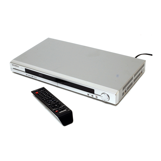
DVD- RECORDER
Chassis : ANDES (3rd Generation)
DVD-R130/
DVD-R131/
SERVICE
DVD-RECORDER
COM, EUR, SED, XEB, XEC, XEE, XEF, XEG,
XEH, XEN, XEO, XET, XEU, XEV, AFR, AND,
SMR, UMG, XSG, XFA, XSA, RAD, XSH, XSS,
XST, XTL, SAM, XSE, XSV, CHN, HAC, TAW,
SEO
COM, EUR, SED, XEB, XEC, XEE, XEF, XEG,
XEH, XEN, XEO, XET, XEU, XEV, AFR, AND,
SMR, UMG, XSG, XFA, XSA, RAD, XSH, XSS,
XST, XTL, SAM, XSE, XSV, CHN, HAC, TAW,
SEO
Manual
Merit & Character regarding Product
ΠMulti format recording
DVD-RW/ DVD-R
´ Multi format playback
DVD/ DVD-RAM/ DVD-RW/ DVD-R
CD/ CD-R/ CD-RW/ MP3/ JPEG/ VCD
ˇ Recording mode
XP(1Hour)/ SP(2Hour)/ LP(4Hour)/ EP(6~8Hour)
¨ Progressive scan
ˆ DV Input
Ø 49mm Slim Design
∏ Quick Recording
Advertisement
Table of Contents

Related Manuals for Samsung DVD-R130


Summary of Contents for Samsung DVD-R130
- Page 1 Ø 49mm Slim Design ∏ Quick Recording © Samsung Electronics Co., Ltd. APR. 2006 This Service Manual is a property of Samsung Electronics Co.,Ltd. Any unauthorized use of Manual can be punished under applicable Printed in Korea international and/or domestic law.
-
Page 2: Table Of Contents
(4-1) 4-2 PCB Location (4-6) 5. Trouble Shooting (5-1 ~ 5-12) 6. Exploded View and Parts List (6-1 ~ 6-6) 6-1 Cabinet Assembly (DVD-R130) (6-2) 6-2 Cabinet Assembly (DVD-R131) (6-4) 7. Electrical Parts List (7-1 ~ 7-14) 8. Block Diagram... - Page 3 CONTENTS 9. Wiring Diagram (9-1 ~ 9-2) 10. PCB Diagrams (10-1 ~ 10-6) 10-1 Main PCB (10-2) 10-2 Jack PCB (10-4) 10-3 Key PCB (10-6) 11. Schematic Diagrams (11-1 ~ 11-20) 11-1 S.M.P.S. (Jack PCB) (11-3) 11-2 A2 / NICAM (Jack PCB) (11-4) 11-3 Connection (Jcak PCB) (11-5)
- Page 4 CONTENTS 12. Operating Instructions (12-1 ~ 12-10) 13. Circuit Operating Descriptions (13-1 ~ 13-16) 13-1 Power (13-1) 13-2 AV Codec (13-4) 13-3 SERVO (DVP Multi Drive) (13-7) 13-4 Video In/Out block (13-9) 13-5 Audio (13-12) 13-6 Tuner (13-14) 13-7 IF (13-15) 14.
-
Page 5: Precautions
Metal Part an electrical return path to the chassis. Any current measured must not exceed 0.5mA. Reverse the instrument power cord plug in the out- ohmmeter let and repeat the test. See Fig. 1-1. Fig. 1-2 Insulation Resistance Test Samsung Electronics... - Page 6 (5) antenna wiring. Always inspect in all areas tinuously and new instructions are issued whenev- for pinched, out-of-place, or frayed wiring, Do not er appropriate. change spacing between a component and the printed-circuit board. Check the AC power cord for damage. Samsung Electronics...
-
Page 7: Servicing Precautions
Components identi- fied by shading, by( ) or by ( ) in the circuit dia- gram are important for safety or for the characteris- tics of the unit. Always replace them with the exact replacement components. Samsung Electronics... -
Page 8: Esd Precautions
(6) Do not remove a replacement ESD device from its protective package until immediately before your are ready to install it.(Most replacement ESD devices are packaged with leads electrically short- ed together by conductive foam, aluminum foil or comparable conductive materials). Samsung Electronics... -
Page 9: Handling The Optical Pick-Up
◆ Be sure to put on a wrist strap grounded to the sheet. ◆ Be sure to lay a conductive sheet made of copper etc. Which is grounded to the table. Samsung Electronics... - Page 10 Precautions MEMO Samsung Electronics...
-
Page 11: Product Specification (2-1 ~ 2-4)
Audio compression format Dolby digital 2ch/256kbps, MPEG-II XP (about 8 Mbps), SP (about 4 Mbps), LP (about 2 Mbps), Recording Recording Quality EP (about 1,2 Mbps or about 0,8 Mbps) Audio frequency characteristics 20 Hz ~ 20 KHz Samsung Electronics... -
Page 12: Chassis Product Specification
Product Specification 2-2 Chassis Product Specification General Model Name DVD-R120 DVD-R130 DVD-R131 Info Function Standard Standard Standard COLOR SYSTEM SYSTEM BROADCAST SYSTEM I, B/G, D/K, L/L’ I, B/G, D/K, L/L’ I, B/G, D/K, L/L’ AUTO CLOCK DVD-RAM DVD-R DVD-RW VIDEO... -
Page 13: Option Product Specification
Product Specification 2-3 Option Product Specification Description Fig Description Parts No Remark Remote Model Standard of AK59-00055B Control DVD-R130/XEU Model Standard of Batteries for 4301-001035 DVD-R130/XEU Remote Control S.N.A Model Standard of User’s Manual DVD-R130/XEU Model Standard of Quick Guide DVD-R130/XEU S.N.A... - Page 14 Product Specification MEMO Samsung Electronics...
-
Page 15: Software Update
• Write the downloaded file onto a blank CD-R or CD-RW disc, using the following settings : 1) Download the software update file from the samsung internet site. (www.samsung.com) 2) Write the file to disc using the CD-RW of your computer. - Page 16 Fig. 3-4 Fig. 3-5 6) After removing the update disc, turn off the unit with power button. And there after turn on the unit with power button and then the will be closed. The drive firmware is now completed. Samsung Electronics...
-
Page 17: Flash Update
Write the downloaded file onto a blank CD-R or CD-RW disc, using the following settings : 1) Download the software update file from the samsung internet site. (www.samsung.com) 2) Write the file to disc using the CD-RW of your computer. - Page 18 The message below will be displayed in the screen after update is completed and the tray will open automatically. * If the message to the left isn’t displayed after 10minutes and the unit is no longer functioning properly, contact a samsung authorized service center. Flash Update Flash memory is successfully updated.
-
Page 19: Disassembly And Reassembly
1) Remove 5 Screws Œ, ´, ˇ. 2) Lift up the Top Cabinet in direction of arrow. ´ 1 SCREW (3 * 10 W) Œ 3 SCREWS (3 * 10 W) ˇ 1 SCREW (3 * 10 W) Fig. 4-1 Top Cabinet Removal Samsung Electronics... - Page 20 Disassembly and Reaasembly 4-1-2 Ass’y Front-Cabinet Removal 1) Release 6 Hooks Œ, ´, ˇ, ¨ and Ass’y Front-Cabinet ˆ. Œ 1 HOOK ¨ 2 HOOKS ´ 1 HOOK ˇ 2 HOOKS ˆ ASS'Y FRONT-CABINET Fig. 4-2 Ass’y Front-Cabinet Removal Samsung Electronics...
- Page 21 4-1-3 Ass’y Deck Removal 1) Remove 4 Screws Œ, ´ from the Ass’y Deck ˇ and lift it up. ´ 2 SCREWS Œ 2 SCREWS (3 * 8 Y) (3 * 10 Y) ˇ ASS'Y-DECK Fig. 4-3 Ass’y Deck Removal Samsung Electronics...
- Page 22 Disassembly and Reaasembly 4-1-4 Main PCB Removal 1) Remove 2 Screws Œ, from the Main PCB ´ and lift it up. Œ 2 SCREWS (3 * 10 Y) ´ MAIN PCB Fig. 4-4 Main PCB Removal Samsung Electronics...
- Page 23 1) Remove 7 Screws Œ, ´, ˇ ,¨from the Jack PCB ˆ and lift it up. Œ 4 SCREWS ¨ 1 SCREW (3 * 6 Y) (3 * 6 Y) ˆ JACK PCB ´ 1 SCREW (3 * 8 W) ˇ 1 SCREW (3 * 6 W) Fig. 4-5 Jack PCB Removal Samsung Electronics...
-
Page 24: Pcb Location
Disassembly and Reaasembly 4-2 PCB Location MAIN PCB JACK PCB Fig. 4-6 PCB Location Samsung Electronics... -
Page 25: Troubleshooting
PAFT1 is normal? PVDL1,PSDZ1,PVZL1 Change short circuited or SHORT and OPEN opened parts Are normal? Is there voltage at Change PQIZ1 IC. PQIZ1[Pin 5]? (Over 10V) Operation of PQIZ1 is Replace PQIZ1 Normal? Check feed back PQIZ1[PIN 3] Is 5.8V Samsung Electronics... - Page 26 Set audio setting to can Decode Current Setting is PCM. Bitstream in customer Bit-Steam menu. ChecK Digital Audio data Replace Main PCB at pin 2 of CN4 (MAIN PCB) Replace AVJ5 Check 5V AVJ5 AUDIO DATA Check the Cable Samsung Electronics...
- Page 27 # IF Recorder is under PSO (progressive scan output) MODE, it does not output the CVBS& S-Video signal. Video signal of Check the connection between About P-P1V appears at VIC1 and output jack. Output Jack? CVBS(Color-bar) Check the RCA Cable Samsung Electronics...
- Page 28 # Nomal level : pin 10 is 1Vpk-pk pin 8 is 0.28V on color burst Video signal of Check the connection between About P-P1V appears at VIC1 and output jack. Output Jack? Y(Color-bar) C(Color-bar) Check the RCA cable Samsung Electronics...
- Page 29 Has about p-p 1V level? Pin 8,10,12 in IC216 and Pin-Jack. Pin 35 In IC216 Check Pin 35 in IC216 Has about p-p 1V signal? of input power(5V). VIC1 of Main PCB Clock VIC1 of Main PCB DATA Samsung Electronics...
- Page 30 Tuner input line signal is OK? Connect tuner line to TV directly (jack PCB) Supplied power Pin 3 : 5V pin 14 : 33V check its line (Pin 3 : 5V pin 14 : 33V) for (jack PCB) tuner is OK? Samsung Electronics...
- Page 31 Video signal of Check the connection between About 1V pk-pk appears at VIC1 and output jack. Output Jack? # Nomal level : pin 6 is 1Vpk-pk pin 2/4 is + 0.35V Check the RCA cable Pb(Color-bar) Pr(Color-bar) Y(Color-bar) Samsung Electronics...
- Page 32 Check the audio signal pin7 Replace Main PCB pin8 of AIC1 (MAIN PCB) Check digital clock and Replace MAIN PCB data pin1, 2, 3, 16 of AIC1 (MAIN PCB) AUDIO DATA Check the passive parts arond Jack pin. Samsung Electronics...
- Page 33 Tuner input line signal Tuner line connect TV directly. is OK? IIC line (SCL,SDA) from Check the IIC line front micom is OK? Does FX1 make 8MHz Check FX1 or around elements signal? (jack PCB) Change FIC1 or check around elements Samsung Electronics...
- Page 34 Check he power power OK? (5v, 12v) Is the 40pin FFC cable(betweenmain & deck) Reinsert FFC cable correctly inserted correctly? Is the wavefrom Change the Main board of DIC3 pin26 normal? (MAIN PCB) DIC3-Pin26 Change the deck 5-10 Samsung Electronics...
- Page 35 4.5MHz signal from 15 pin Check the SIF signal or tuner of tuner(TTM1) is OK? Does NX1 make Check NX1 or around elements 18.432MHz signal? (jack PCB) Tuner Audio If TIC1 is normal, refer to audio line in abnomal Samsung Electronics 5-11...
- Page 36 Troubleshooting MEMO 5-12 Samsung Electronics...
-
Page 37: Exploded View And Parts List
Page 6-1 Cabinet Assembly (DVD-R130) - - - - - - - - - - - - - - - - - - - - - - - - - - - - - - - - 6-2 Cabinet Assembly (DVD-R131) - - - - - - - - - - - - - - - - - - - - - - - - - - - - - - - -... -
Page 38: Cabinet Assembly (Dvd-R130)
Exploded Views and Parts List 6-1 Cabinet Assembly (DVD-R130) W009 W200 W009 H001 P001 FL261 W272 W272 W275 W275 P022 C015 W272 P025 W272 W268 S.N.A.: Service Not Available A001 C001 W009 P007 C002 C657 Samsung Electronics... - Page 39 Exploded Views and Parts List Loc. No Parts No. Description ; Specification Q’ty S.N.A Remark A001 AK59-00055B REMOCON-ASSY;DVD-R130/XEG,SEC,197. C001 AK97-01447K ASSY-CABINET FRONT;HIPS 94 HB,DVD- C002 AK64-01432A DOOR-TRAY;DVD-R130,ABS 94HB,T2,H15 C015 AK64-01375A CABINET-TOP;DVD-R110,PCM,T0.6,W430 C657 AK64-01433C DOOR-JACK;DVD-R130/XEF,ABS 94HB,T2 FL261 3809-001804 FFC CABLE-FLAT;30V,80C,55mm,13P,1m H001 AK97-01553E ASSY-LOADER;,-,SV-R3600,LOADER ASS P001 AK92-00928A ASSY PCB-MAIN;DVD-R130/XEG,PAL...
-
Page 40: Cabinet Assembly (Dvd-R131)
Exploded Views and Parts List 6-2 Cabinet Assembly (DVD-R131) W009 W200 W009 H001 P001 FL261 W272 W272 W275 W275 P022 C015 W272 P025 W272 W268 S.N.A.: Service Not Available A001 C001 W009 P007 C002 Samsung Electronics... - Page 41 Exploded Views and Parts List Loc. No Parts No. Description ; Specification Q’ty S.N.A Remark A001 AK59-00055B REMOCON-ASSY;DVD-R130/XEG,SEC,197.5*48*2 C001 AK97-01464C ASSY-CABINET FRONT;HIPS 94HB,DVD-R129,06 C002 AK64-01690A DOOR-TRAY;DVD-R135,ABS 94HB,T2,H15,W150, C015 AK64-01375B CABINET-TOP;DVD-R130E,PCM,T0.6,W430,L220 C657 AK64-01691C DOOR-JACK;DVD-R129/XEF,ABS 94HB,T2,H15,W FL261 3809-001793 FFC CABLE-FLAT;30V,80C,90mm,40P,0.5mm,UL H001 AK97-01553A ASSY-LOADER;-,SV-R3600,LOADER ASSY...
- Page 42 Exploded Views and Parts List MEMO Samsung Electronics...
-
Page 43: Electrical Parts List
2203-005148 C-CER,CHIP;100nF,10%,16V,X7R,1608 DC81 2203-005148 C-CER,CHIP;100nF,10%,16V,X7R,1608 DC34 2203-005148 C-CER,CHIP;100nF,10%,16V,X7R,1608 DC82 2203-005148 C-CER,CHIP;100nF,10%,16V,X7R,1608 DC35 2203-005148 C-CER,CHIP;100nF,10%,16V,X7R,1608 DC83 2203-005148 C-CER,CHIP;100nF,10%,16V,X7R,1608 DC36 2203-005148 C-CER,CHIP;100nF,10%,16V,X7R,1608 DC84 2203-005148 C-CER,CHIP;100nF,10%,16V,X7R,1608 DC37 2203-005148 C-CER,CHIP;100nF,10%,16V,X7R,1608 DC85 2203-005148 C-CER,CHIP;100nF,10%,16V,X7R,1608 Samsung Electronics This Document can not be used without Samsung’s authorization... - Page 44 2011-001194 R-NET;51ohm,5%,1/16W,L,CHIP,8P,TP, DR39 2007-000102 R-CHIP;100Kohm,5%,1/10W,TP,1608 DRP24 2011-000515 R-NET;4.7Kohm,5%,1/16W,L,CHIP,8P,T DR40 2007-000084 R-CHIP;4.7Kohm,5%,1/10W,TP,1608 DRP25 2011-000515 R-NET;4.7Kohm,5%,1/16W,L,CHIP,8P,T DR41 2007-000074 R-CHIP;100ohm,5%,1/10W,TP,1608 DRP26 2011-000515 R-NET;4.7Kohm,5%,1/16W,L,CHIP,8P,T DR42 2007-000074 R-CHIP;100ohm,5%,1/10W,TP,1608 DRP27 2011-000515 R-NET;4.7Kohm,5%,1/16W,L,CHIP,8P,T DR43 2007-001014 R-CHIP;51OHM,5%,1/10W,TP,1608 Samsung Electronics This Document can not be used without Samsung’s authorization...
- Page 45 VC12 2203-005148 C-CER,CHIP;100nF,10%,16V,X7R,1608 VC13 2203-005148 C-CER,CHIP;100nF,10%,16V,X7R,1608 2203-000491 C-CER,CHIP;2.2nF,10%,50V,X7R,1608 VC14 2203-005148 C-CER,CHIP;100nF,10%,16V,X7R,1608 2203-000257 C-CER,CHIP;10nF,10%,50V,X7R,1608 VC15 2203-005148 C-CER,CHIP;100nF,10%,16V,X7R,1608 2203-000257 C-CER,CHIP;10nF,10%,50V,X7R,1608 VC16 2203-005148 C-CER,CHIP;100nF,10%,16V,X7R,1608 2203-000257 C-CER,CHIP;10nF,10%,50V,X7R,1608 ACN1 3708-001695 CONNECTOR-FPC/FFC/PIC;13P,1MM,STRA VC17 2203-005148 C-CER,CHIP;100nF,10%,16V,X7R,1608 Samsung Electronics This Document can not be used without Samsung’s authorization...
- Page 46 2401-000598 C-AL;1uF,20%,50V,GP,TP,4x7,5 AHR54 2007-000077 R-CHIP;470ohm,5%,1/10W,TP,1608 AHE40 2401-001250 C-AL;4.7uF,20%,35V,GP,TP,4x5,5 AHR55 2007-000070 R-CHIP;0ohm,5%,1/10W,TP,1608 AHE41 2401-001250 C-AL;4.7uF,20%,35V,GP,TP,4x5,5 AHR56 2007-000097 R-CHIP;47Kohm,5%,1/10W,TP,1608 AHE42 2401-001250 C-AL;4.7uF,20%,35V,GP,TP,4x5,5 AHR57 2007-000097 R-CHIP;47Kohm,5%,1/10W,TP,1608 AHE43 2401-001250 C-AL;4.7uF,20%,35V,GP,TP,4x5,5 AHR9 2007-000123 R-CHIP;1.5Kohm,5%,1/10W,TP,1608 Samsung Electronics This Document can not be used without Samsung’s authorization...
- Page 47 HEADER-BOARD TO BOARD;BOX,30P,2R,2 0402-000165 DIODE-RECTIFIER;1N5819,40V,1A,DO-4 MCN3 3711-005563 HEADER-BOARD TO BOARD;BOX,30P,2R,2 0402-000165 DIODE-RECTIFIER;1N5819,40V,1A,DO-4 0402-001533 DIODE-RECTIFIER;1N5408,1000V,3A,-, 0403-001083 DIODE-ZENER;UDZ9.1B,8.85-9.23V,200 2401-000249 C-AL;100uF,20%,10V,GP,TP,6.3x5,5 0402-000127 DIODE-RECTIFIER;1N4002,100V,1A,DO- 2007-000029 R-CHIP;0ohm,5%,1/8W,TP,2012 2401-002165 C-AL;100uF,20%,16V,GP,TP,6.3x7,5 2007-001167 R-CHIP;75ohm,5%,1/10W,TP,1608 2401-002165 C-AL;100uF,20%,16V,GP,TP,6.3x7,5 2007-000070 R-CHIP;0ohm,5%,1/10W,TP,1608 Samsung Electronics This Document can not be used without Samsung’s authorization...
- Page 48 PPRF2 2001-000429 R-CARBON;1KOHM,5%,1/8W,AA,TP,1.8X3 PAVV2 1405-001026 VARISTOR;470V,600A,9x7mm,TP PPRF3 2001-000429 R-CARBON;1KOHM,5%,1/8W,AA,TP,1.8X3 PAWT1 3711-000203 HEADER-BOARD TO CABLE;1WALL,2P/3P, PPRF4 2001-000429 R-CARBON;1KOHM,5%,1/8W,AA,TP,1.8X3 PBCU1 2201-002044 C-CERAMIC,DISC;0.1NF,10%,400V,Y5P, PPRF5 2001-000281 R-CARBON;100OHM,5%,1/8W,AA,TP,1.8X PBCU2 2201-002044 C-CERAMIC,DISC;0.1NF,10%,400V,Y5P, PPRF6 2001-000429 R-CARBON;1KOHM,5%,1/8W,AA,TP,1.8X3 Samsung Electronics This Document can not be used without Samsung’s authorization...
- Page 49 2007-001167 R-CHIP;75ohm,5%,1/10W,TP,1608 2401-001479 C-AL;470uF,20%,10V,GP,TP,6.3*11mm, SR25 2007-000134 R-CHIP;33Kohm,5%,1/10W,TP,1608 SE10 2401-002165 C-AL;100uF,20%,16V,GP,TP,6.3x7,5 SR27 2007-000070 R-CHIP;0ohm,5%,1/10W,TP,1608 SE11 2401-001479 C-AL;470uF,20%,10V,GP,TP,6.3*11mm, SR28 2007-001167 R-CHIP;75ohm,5%,1/10W,TP,1608 SE13 2401-002165 C-AL;100uF,20%,16V,GP,TP,6.3x7,5 2007-000084 R-CHIP;4.7Kohm,5%,1/10W,TP,1608 2401-001479 C-AL;470uF,20%,10V,GP,TP,6.3*11mm, SR30 2007-000078 R-CHIP;1Kohm,5%,1/10W,TP,1608 Samsung Electronics This Document can not be used without Samsung’s authorization...
- Page 50 FRAME-MAIN;DP-R3,ABS,ABS,-,BLK,-,W 2203-000189 C-CER,CHIP;100nF,+80-20%,25V,Y5V,1 3708-001331 CONNECTOR-FPC/FFC/PIC;40P,0.5mm,SM 2203-000189 C-CER,CHIP;100nF,+80-20%,25V,Y5V,1 2203-006048 C-CER,CHIP;100nF,10%,10V,X7R,1005 2203-000189 C-CER,CHIP;100nF,+80-20%,25V,Y5V,1 PC10 2402-000179 C-AL,SMD;47uF,20%,16V,GP,TP,6.6x6. 2203-000998 C-CER,CHIP;0.047nF,5%,50V,C0G,1608 PC12 2203-006048 C-CER,CHIP;100nF,10%,10V,X7R,1005 0401-000005 DIODE-SWITCHING;1N4148,75V,150mA,D PC14 2203-006048 C-CER,CHIP;100nF,10%,10V,X7R,1005 2401-002300 C-AL;47uF,20%,50V,GP,TP,6.3x11,5 PC15 2404-001131 C-TA,CHIP;22UF,10%,10V,GP,TP,3528 Samsung Electronics This Document can not be used without Samsung’s authorization...
- Page 51 RR44 2007-000151 R-CHIP;15Kohm,5%,1/16W,TP,1005 RC46 2203-000438 C-CER,CHIP;1nF,10%,50V,X7R,1005 RR45 2007-000151 R-CHIP;15Kohm,5%,1/16W,TP,1005 RC47 2203-000627 C-CER,CHIP;0.022nF,5%,50V,C0G,1005 RR46 2007-000171 R-CHIP;0ohm,5%,1/16W,TP,1005 RC48 2203-000438 C-CER,CHIP;1nF,10%,50V,X7R,1005 S.N.A AK92-00876A ASSY PCB-F/END;SV-R3600,F/END ASSY RC49 2203-000438 C-CER,CHIP;1nF,10%,50V,X7R,1005 S.N.A AH31-00025A MOTOR-LOADING;RF-300EA-1D390,DP-7, Samsung Electronics This Document can not be used without Samsung’s authorization...
- Page 52 UC45 2203-000438 C-CER,CHIP;1nF,10%,50V,X7R,1005 S.N.A AK67-00034A LENS-PBS;SOH-DR3,GLS,WHT,8.7*4.0,2 UC46 2203-006048 C-CER,CHIP;100nF,10%,10V,X7R,1005 S.N.A AK67-00035A LENS-MR;SOH-DR3,GLS,WHT,5.0*4.0,2. UC47 2203-000254 C-CER,CHIP;10nF,10%,16V,X7R,1005 S.N.A AK67-00036A LENS-DVD GT;SOH-DR3,GLS,WHT,2.5*3. UC48 2203-006048 C-CER,CHIP;100nF,10%,10V,X7R,1005 S.N.A AK67-00038A LENS-CBS;SOH-DR3,GLS,WHT,3.0*3.0,3 UC49 2203-006048 C-CER,CHIP;100nF,10%,10V,X7R,1005 Samsung Electronics 7-10 This Document can not be used without Samsung’s authorization...
- Page 53 R-CHIP;3.9KOHM,5%,1/16W,TP,1005 VR13 2007-000034 R-CHIP;1OHM,5%,1/4W,TP,3216 UR43 2007-000148 R-CHIP;10Kohm,5%,1/16W,TP,1005 VR14 2007-000034 R-CHIP;1OHM,5%,1/4W,TP,3216 UR44 2007-000171 R-CHIP;0ohm,5%,1/16W,TP,1005 VR16 2007-000034 R-CHIP;1OHM,5%,1/4W,TP,3216 UR47 2007-000148 R-CHIP;10Kohm,5%,1/16W,TP,1005 VR18 2007-000034 R-CHIP;1OHM,5%,1/4W,TP,3216 UR48 2007-000148 R-CHIP;10Kohm,5%,1/16W,TP,1005 VR20 2007-000148 R-CHIP;10Kohm,5%,1/16W,TP,1005 7-11 Samsung Electronics This Document can not be used without Samsung’s authorization...
- Page 54 AK61-00488A BRACKET-DECK;DP-RW2,SECC US COATIN AK61-00490A SPRING ETC-SHAFT PU;DP-RW2,PW2,0.8 AC99-40324X ASSY-FPCB,c;-,SOH-DR2.5,RAMBO2.5 F AC99-80325S ASSY-FPCB,mrp;-,SOH-DR2.5,RAMBO2.5 AC99-90327A ASSY-FPCB,m;-,SOH-DR2.5,RAMBO2.5 F AK97-01328A ASSY-HOLDER CHUCK;ASSY,DP-RW2,DP-R AK97-01331A ASSY-CLAMPER;POM+MAGNET,DP-RW2,ASS AK61-00486A BODY CLAMPER-UPPER;DP-RW2,POM,T0.7 AK61-00487A BRACKET-CLAMPER;DP-RW2,SECC,T0.6,1 BG33-30001D MAGNET-CLAMPER;-,-,-,-,13.5x6x1.1 Samsung Electronics 7-12 This Document can not be used without Samsung’s authorization...
- Page 55 8-6 HA118827F-E Block Diagram - - - - - - - - - - - - - - - - - - - - - - - - - - - - - - - - - Samsung Electronics This Document can not be used without Samsung’s authorization.
-
Page 56: All Block Diagram
FRONT DIC1(MAIN) MICOM S5L3210 FIC1 COMPONENT SWITCH FRONT IEEE1394 HA118827 S-VIDEO TIC1(MAIN) (JACK) CVBS 1394 JACK REMOCON AUDIO DAC INPUT AIC1 PCM1753 VIDEO SCART AV2(EXT) DECODER (TW9909) COAXIAL OPTICAL Samsung Electronics This Document can not be used without Samsung’s authorization. -
Page 57: Aic1(Pcm1753) Audio Da Block Diagram
Delta-Sigma (FMT) ML Function Modulator Serial Controller (MUTE) MC Output Amp and Control Low-pass Filter Port (DEMP) MD System Clock (TEST) System Clock Zero Detect Power Supply Manager Samsung Electronics This Document can not be used without Samsung’s authorization. -
Page 58: System Block Diagram
Sync Composite separator sync signal data SEPC separation separator circuit control SEPOUT CTRL1 XtalIN XtalOUT CVCR CDLR CVIN CVOUT 1, V 2, V (CHABLK) (MUTE) 1, V 2, V Samsung Electronics This Document can not be used without Samsung’s authorization. -
Page 59: Tic1(Tw9906) Video Decoder Block Diagram
L ine-lock CLKX2 cl ock CLKX1 Ge nerator Cl ock 27 Mhz INTREQ VBI Slicer VBI FIFO SIAD0 2 Wi re AMXCLK SCLK Serial AMCLK SDAT ASCLK ALRCLK Samsung Electronics This Document can not be used without Samsung’s authorization. -
Page 60: Internal Block Diagram
Block Diagrams 8-5 Internal Block Diagram Samsung Electronics This Document can not be used without Samsung’s authorization. -
Page 61: Ha118827F-E Block Diagram
AV2-L AV3-L Hifi-L TU TU TU ALWAYS5V orAV3 (Heavy Line block input Futoshi line route(AV1 --> AV2AV2 --> AV1), powersupply) It operates at the Stanby Mode time. (30,34,36Pinpower OFF) Samsung Electronics This Document can not be used without Samsung’s authorization. - Page 62 Block Diagrams MEMO Samsung Electronics This Document can not be used without Samsung’s authorization.
-
Page 63: Wiring Diagram
9. Wiring Diagram Samsung Electronics... - Page 64 Wiring Diagram MEMO Samsung Electronics...
-
Page 65: Pcb Diagrams
10-3 Key PCB - - - - - - - - - - - - - - - - - - - - - - - - - - - - - - - - - - - - - - - - - - - - - - 10-6 Samsung Electronics 10-1... - Page 66 PCB Diagrams 10-1 Main PCB COMPONENT SIDE RIC1 AIC1 DIC1 DIC2 DIC3 RIC2 10-2 Samsung Electronics...
- Page 67 PCB Diagrams CONDUCTOR SIDE DIC5 VIC1 TIC1 DIC6 Samsung Electronics 10-3...
- Page 68 PCB Diagrams 10-2 Jack PCB COMPONENT SIDE 10-4 Samsung Electronics...
- Page 69 PCB Diagrams CONDUCTOR SIDE NIC1 IC216 OIC2 FIC1 AIC1 Samsung Electronics 10-5...
-
Page 70: Key Pcb
PCB Diagrams 10-3 Key PCB COMPONENT SIDE CONDUCTOR SIDE 10-6 Samsung Electronics... -
Page 71: Schematic Diagrams
11-18 Key (Key PCB) - - - - - - - - - - - - - - - - - - - - - - - - - - - - - - - - - - - - - - - - - 11-20 Samsung Electronics This Document can not be used without Samsung’s authorization. 11-1... -
Page 72: Jack Pcb
Memory / AV Block Interface I/O Block A2/NICAM Block Block Block MPEG Encoding Power System & Decoding Block Control VPS/PDC OSD Block - Jack PCB - Main PCB 11-2 Samsung Electronics This Document can not be used without Samsung’s authorization. -
Page 73: S.m.p.s. (Jack Pcb)
Schematic Diagrams 11-1 S.M.P.S. (Jack PCB) Power Samsung Electronics This Document can not be used without Samsung’s authorization. 11-3... -
Page 74: A2 / Nicam (Jack Pcb)
Schematic Diagrams 11-2 A2 / NICAM (Jack PCB) Audio Power 11-4 Samsung Electronics This Document can not be used without Samsung’s authorization. -
Page 75: Connection (Jcak Pcb)
Schematic Diagrams 11-3 Connection (Jcak PCB) Power Samsung Electronics This Document can not be used without Samsung’s authorization. 11-5... -
Page 76: Front Av (Jack Pcb)
Schematic Diagrams 11-4 Front AV (Jack PCB) ideo Audio Power 11-6 Samsung Electronics This Document can not be used without Samsung’s authorization. -
Page 77: I/O (Jack Pcb)
Schematic Diagrams 11-5 I/O (Jack PCB) Video Power Audio Samsung Electronics This Document can not be used without Samsung’s authorization. 11-7... -
Page 78: I/O Switching (Jack Pcb)
Schematic Diagrams 11-6 I/O Switching (Jack PCB) Video Audio Power 11-8 Samsung Electronics This Document can not be used without Samsung’s authorization. -
Page 79: Led Driver (Jack Pcb)
Schematic Diagrams 11-7 LED Driver (Jack PCB) Video Audio Power Samsung Electronics This Document can not be used without Samsung’s authorization. 11-9... -
Page 80: Power (Jack Pcb)
Schematic Diagrams 11-8 Power (Jack PCB) 11-10 Samsung Electronics This Document can not be used without Samsung’s authorization. -
Page 81: System Control (Jack Pcb)
Schematic Diagrams 11-9 System Control (Jack PCB) Power Samsung Electronics This Document can not be used without Samsung’s authorization. 11-11... -
Page 82: Tm (Jack Pcb)
Schematic Diagrams 11-10 TM (Jack PCB) ideo Audio Power 11-12 Samsung Electronics This Document can not be used without Samsung’s authorization. -
Page 83: Vps_Pdc (Jack Pcb)
Schematic Diagrams 11-11 VPS_PDC (Jack PCB) Power Samsung Electronics This Document can not be used without Samsung’s authorization. 11-13... -
Page 84: Dvd Av Codec (Main Pcb)
Schematic Diagrams 11-12 DVD AV Codec (Main PCB) 11-14 Samsung Electronics This Document can not be used without Samsung’s authorization. -
Page 85: Dvd Audio In/Out (Main Pcb)
Schematic Diagrams 11-13 DVD Audio In/Out (Main PCB) Samsung Electronics This Document can not be used without Samsung’s authorization. 11-15... -
Page 86: Dvd Ddr (Main Pcb)
Schematic Diagrams 11-14 DVD DDR (Main PCB) Power 11-16 Samsung Electronics This Document can not be used without Samsung’s authorization. -
Page 87: Dvd Main Connector (Main Pcb)
Schematic Diagrams 11-15 DVD Main Connector (Main PCB) ideo Audio Power Samsung Electronics This Document can not be used without Samsung’s authorization. 11-17... -
Page 88: Dvd Video Deocder (Main Pcb)
Schematic Diagrams 11-16 DVD Video Deocder (Main PCB) Video Power 11-18 Samsung Electronics This Document can not be used without Samsung’s authorization. -
Page 89: Ieee 1394 (Main Pcb)
Schematic Diagrams 11-17 IEEE 1394 (Main PCB) Power Samsung Electronics This Document can not be used without Samsung’s authorization. 11-19... -
Page 90: Key (Key Pcb)
Schematic Diagrams 11-18 Key (Key PCB) Power 11-20 Samsung Electronics This Document can not be used without Samsung’s authorization. -
Page 91: Operating Instructions
12. Operating Instructions Front Panel (DVD-R130) 1. STANDBY/ON 7. SEARCH/SKIP Turns the DVD Recorder on and off. Go to the next title/chapter/track or go back to the previous title/chapter/track. 2. AV3 IN 8. PLAY/PAUSE Connect external equipment. Plays a disc or pauses playback/recording. -
Page 92: Front Panel Display
10. COMPONENT VIDEO OUT audio input jack. Connects to equipment having Component video output. The Antenna connection does not pass ■ output signal of DVD. To watch a DVD on NOTE your TV, you must connect audio/video cables. English - 12-2 Samsung Electronics... -
Page 93: Tour Of The Remote Control
Press this when you use a DVD recorder. 28. INPUT SEL. Button Select line input signal in external input mode [PROG, AV input or DV INPUT(DVD-R130, R131 only)] 29. ZOOM Button Press this to enlarge the screen. 1. STANDBY/ON Button 2. -
Page 94: Quick Overview
Other type of connecting the Video output cable Other type of connecting the Audio output cable Connecting to AV3 IN, DV input jack (DVD-R130, R131 only) Quick Overview..........17 Connecting the DVD Recorder......18 Additional connections ........18 Other type of connecting the Video output cable........19 Other type of connecting the Audio output cable........21... -
Page 95: Additional Connections
DVD Recorder, even when the DVD Recorder is turned off. TV mode ■ Press the TV/DVD button on remote control, then “TV” appear on Front LED display (or turn off DVD Recorder). - English Samsung Electronics 12-5... -
Page 96: Other Type Of Connecting The Video Output Cable
It is recommended that the user switch the connection to the ‘standard definition’ output. If there are questions regarding our TV set compatibility with this model 576p DVD Recorder, please contact our customer service centre. English - 12-6 Samsung Electronics... -
Page 97: Output Jacks
DVD Recorder must be connected to the exact corresponding component input jacks on your TV. Progressive setting is only available when ■ the Video Out is set to Component. (See page 34) - English Samsung Electronics 12-7... -
Page 98: Other Type Of Connecting The Audio Output Cable
Dolby Laboratories. white “DTS” and “DTS Digital Out” are trademarks of DTS, Inc. Case 1 : Connecting to your TV Front(L) Front(R) If your TV has audio input jacks, use this connection. speaker speaker yellow white English - 12-8 Samsung Electronics... -
Page 99: Output Jack
DTS decoder and a digital input jack, use this connection. To enjoy Dolby Digital, MPEG2 or DTS sound, you will need to set up the audio settings. (See pages 32-33) Rear(L) Rear(R) Front(L) Front(R) Subwoofer Centre - English Samsung Electronics 12-9... -
Page 100: Quick Recording Setting
No Disc Programme Programme EP Mode Time : 6 Hours System Clock Set Chapter Creator : Off Setup Setup Language Quick Recording : Off Audio Video Parental Control Install MOVE RETURN EXIT MOVE RETURN EXIT - English 12-10 Samsung Electronics... -
Page 101: Audio Options
NOTE LPCM sound track is always outputted as PCM. It has no relation with Digital Output setting. Be sure to select the correct Digital ■ Output or you will hear no sound or loud noise. English - Samsung Electronics 12-11... - Page 102 Operating Instructions MEMO 12-12 Samsung Electronics...
-
Page 103: Circuit Operating Descriptions
4) PLRU1 : Rush current limit resistance at the momemt of power cord insertion. · Without PLRU1, the bridge diode might be damaged as the rush current increases. (b) SNUBBER Circuit : PSRZ1, PSRZ2, PSCX1, PSCZ2, PSDZ1 Samsung Electronics 13-1... - Page 104 # Use the output of transformer as PQIZ1 Vcc : The loads are different before and after PQIZ1 driving. (Vcc of PQIZ1 decreases below OFF voltage , using only the resistance dut to lode increase after PQIZ1 driving.) (d) Feedback Control Circuit 3.3V PPDD2 Fig. 13-3 13-2 Samsung Electronics...
- Page 105 (SNUBBER) 5V Rectified 5V Rectified Rectified Circuit Smoothing Circuit VoltageCircuit (x3) 12V Rectified 12V Rectified Smoothing Circuit VoltageCircuit (X3) PWM Control Circuit Line Filter (ICE2BSO1) 3.3V Rectified Voltage Smoothing Circuit Detection Circuit Power IN (110V) Fig. 13-4 Samsung Electronics 13-3...
-
Page 106: Av Codec
(VIDEO DEC) Front Panel I/F IC601 MN101DF10G (Front MICOM) Fig. 13-5 · Main system control · ATAPI interface with DVD-Multi Drive · A/V Encoding/Decoding · Analog Progressive/interlaced video output · Transcoding/rating · IEEE 1394 link layer function 13-4 Samsung Electronics... - Page 107 SD sources. 2) Host Interface The host communication functions include initializing the DMN-8602 device, downloading software to the local SDRAM, sending commands, monitoring status, and downloading graphics data such as OSD bitmap. Samsung Electronics 13-5...
- Page 108 The IDC bus is a simple, two-wire, bidirectional communication bus. The two signals, clock and data, are com mon to every device connected to the bus. In this system, IDC bus is connected to EEPROM(DIC8) and Video Decoder(TIC1) 13-6 Samsung Electronics...
-
Page 109: Servo (Dvp Multi Drive)
2 Direct Seek with Velocity Control 3 Step Motor Control: Macro Seek 4 De-Track and Lens Shift Detection and Compensation 5 Center Error Control 6 DVD Layer Jump 7 Tilt Detect and Compensation DP2 performs High Speed ECC and CD DA Decoder. Samsung Electronics 13-7... - Page 110 ENDEC Pick up Miscellaneous Signal LD,LD Driver (DFT/LPP ATAPI chip /WOBBLE) (ZIC1) Focus Actuator Processor Tracking Actuator APC & OPC TILT Actuator WRITE STRATEGY Sled Spindle Tray Motor Motor Motor Motor Driver MICOM (MIC1) Deck Fig. 13-7 13-8 Samsung Electronics...
-
Page 111: Video In/Out Block
13-4 Video In/out Block DVD-R130 has the two single CVBS Video input(AV3) and two Scart input from AV1 or AV2. AV3 Video input is CVBS at the at the Front Panel. AV2 Scart has CVBS & RGB input and CVBS output, AV1 Scart is vice versa at the Rear Panel. - Page 112 VIN EXT BIAS LIN TV BLK IN MUTE LOUT TV LIN D LOUT TV LIN EXT FS OUT FS IN BIAS2 PORT1 ROUT TV RIN TV ROUT EXT RIN EXT PORT2 RIN D GND 2 Fig. 13-9 13-10 Samsung Electronics...
- Page 113 CVBS, Y, C, Y(R), Cb(B), Cr(R) outputted from video encoder are inputted to VIC1 [Pin4, 6, 2, 10, 12, 14] respec- tively. The signal to which gain is adjusted by amplifier is outputted from jack via 75ohm Resistance (VR14, 15, 16, 23, 12, 13). Samsung Electronics 13-11...
- Page 114 13-5 Audio 13-5-1 Audio Input Block DVD-R130 has tree stereo line input terminals and internal TV-audio from RF Tuner Block. These four analog audio signal source are converted to digital data by Input Block. Input Block has Multiplexer(AIC51), Input Filter(AIC81, AIC82), and A/D Converter(AIC9).
- Page 115 Circuit Operating Descriptions 13-5-2 Audio output Block DVD-R130 has four stereo analog line out terminal, and two digital output terminal. Decoded signal by DIC1 is inputted to AIC1( D/A converter), then filtered and amplified by AIC4(OP-amp), and finally ouputted via RCA terminal and Scart terminal.
- Page 116 1/8 Prescaler Band Driver OSC Amp 4MHz 15 X-tal Prog.Dirlder Band Driver Phese Code 3wice Bas VHF OCS Recelver Charge Pump L.P.F VHF Mixer -RF Amp VHF OSC Single Tune Double Tune & CLOCK DATA ENABLE LOCK Fig.13-12 13-14 Samsung Electronics...
- Page 117 Tuner Section EQ.Amp N.S.C SIF Trap APC Tine Const SW VCD Tank To Tuner Section Lock Det RF AGC RF AGC Amp IF AGC AFT Tank To Tuner Section AFT OUT VIDEO OUT AUDIO OUT Fig. 13-13 Samsung Electronics 13-15...
- Page 118 Circuit Operating Descriptions MEMO 13-16 Samsung Electronics...
-
Page 119: Reference Information
Reflective layer Semi-reflective layer Polycarbonate Polycarbonate Dual Side Dual Layer : 17GByte Dual Side Single Layer : 9.5GByte Polycarbonate Polycarbonate Semi-reflective layer Reflective layer Reflective layer Bonding layer Bonding layer Reflective layer Reflective layer Semi-reflective layer Polycarbonate Polycarbonate Samsung Electronics 14-1... - Page 120 This can be virtually used as hard-disk, with a random DVD-RAM (more than 100,000 times) read-write access Rewritable Similar to DVD-RAM except than its technology features DVD-RW (About 1,000 times) a separated read-write access more like phonograph than a hard disk. 14-2 Samsung Electronics...
-
Page 121: Dvd-Video Fromat
Recording type Dolby Digital Linear PCM MPEG-1 Layer 2 AUDIO Transmission rate 448Kbps/stream 6.144Mbps/stream 224Kbps 1 Analog CH. Channel 5.1CH/stream 8CH/stream 1 Stream of Dolby Digital 2 Digital CH. (16Bit/44.1KHz) Sampling frequency 48KHz 16, 20, 24Bit/48, 96KHz 16Bit/44.1KHz Samsung Electronics 14-3... - Page 122 Data loss and enables Time efficient compression. Loss area • MPEG-1 (Fixed compression : Max. 1/140) Amount of data - Frame unit compression. - Compresses all data using the same ratio. Video-CD - Fast movements are jagged, and unnatural Time 14-4 Samsung Electronics...
- Page 123 - Various Digital Recordings are possible as shown in the table to the right. Sampling Frequency Bit Rate 16bit 48KHz 20bit 24bit 16bit 96KHz 20bit 24bit • Dolby Digital compatible Audio Mode Channel Format Audio Coding Front Surround (Rear) Remark Mode Mono Stereo Mono Mono Surround Samsung Electronics 14-5...
- Page 124 • Up to 9 angles of view may be stored, enabling the viewer to select a specific viewpoint at a given time. --> Especially, for the Music Video and Sports Title, this provides a more lively image of the scene. Note ; This function is disc-dependent, may not work on all DVDs. 14-6 Samsung Electronics...
- Page 125 - Region 6 : China. - Region 0 : Worldwide (All Code) ˆ Œ ´ Œ Ø ´ Œ ˇ ˆ ¨ ´ ¨ • Adoptation of the Macrovision System disables the copying on to other media. Samsung Electronics 14-7...
- Page 126 - Different Authoring Process are used accoring to the Software developers, and this may affect the DVD image quality. • Authoring Process bit stream Video/Audio MPEG-2 Master Encoding Disc Production bit stream Video/Audio Surround Audio AC-3/MPEG Audio Cutting Subtitle Master Encoding Master Multiplexing bit stream Subtitle Subtitle Master Encoding Authoring Process 14-8 Samsung Electronics...
-
Page 127: About Ieee
However, the specification is open and line scan suppor t could be achieved via Format 7. As for USB 2, it is still in its infancy in machine vision and we are not aware of any kind of machine vision support. Samsung Electronics 14-9... - Page 128 Price 1394 Solution Price with multiple frame grabbers Four Cameras 18,000 Four 1394 Cameras 18,000 Four Frame Grabbers 4,400 One 1394 Interface Card Four Cable One 1394 Hub Four power Supplies Five Cables Total $23,120 Total $18,370 14-10 Samsung Electronics...
- Page 129 - Easy and inexpens ive cabl ing , - The system meet s the expect ations for spee d and accuracy, - The range of inspect able parts is much bigger than with the old syste m. Samsung Electronics 14-11...
- Page 130 Reference Information MEMO 14-12 Samsung Electronics...