Sony AIR-SA10 Service Manual
Hide thumbs
Also See for AIR-SA10:
- Operating instructions manual (28 pages) ,
- Operating instructions (5 pages) ,
- Specifications (1 page)
Table of Contents
Advertisement
SERVICE MANUAL
Ver. 1.0 2008.02
Amplifi er section
U.S.A. model:
AUDIO POWER SPECIFICATIONS
POWER OUTPUT AND TOTAL HARMONIC
DISTORTION:
With 3 ohm loads, both channels driven, from 300 –
20,000Hz; rated 4 watts per channel minimum RMS
power, with no more than 10% total harmonic distor-
tion from 250 milliwatts to rated output.
Other models:
Continuous RMS power output (reference):
4 + 4 W (3 ohms at 1 kHz, 10% THD)
Output
i (stereo mini jack): Accepts headphones with an im-
pedance of 8 ohms or more
Speaker section
Speaker system: Full range, bass-refl ex type
Speaker units: 65 mm, cone type (2)
Nominal impedance: 3 ohms
Wireless transceiver (EZW-RT10)
Communication System: S-AIR Specifi cation version
1.0
Output: 12.0 mW
Frequency band: 2.4000 GHz – 2.4835 GHz
Modulation method: DSSS
Power requirements: DC 3.3 V, 350 mA
Dimensions (w/h/d): 50 mm × 13 mm × 60 mm
17
(2 ×
/
× 2
32
Mass: 24 g (1 oz)
Sony Corporation
9-887-984-01
2008B05-1
Audio Business Group
©
2008.02
Published by Sony Techno Create Corporation
SPECIFICATIONS
3
/
in)
8
AIR-SA10
General
Power requirements:
North American model: 120 V AC, 60 Hz
Power consumption: 15 W
Dimensions (w/h/d): Approx. 300 × 136 × 115 mm
7
3
5
(11
/
× 5
/
× 4
/
in)
8
8
8
Mass: Approx. 2.2 kg (4 lb 14 oz)
Supplied accessories: Wireless transceiver EZW-
RT10 (1)
Design and specifi cations are subject to change with-
out notice.
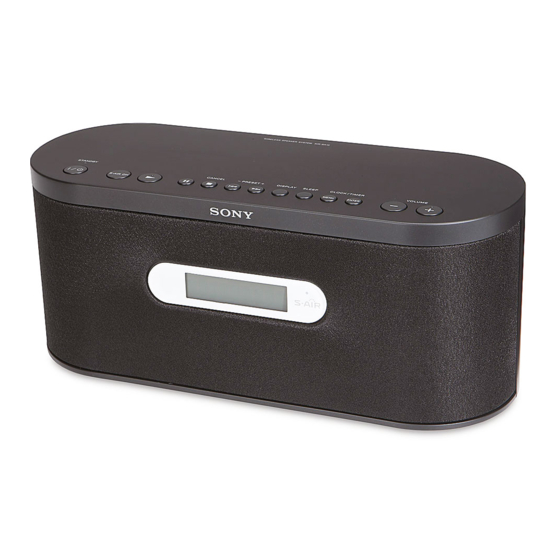
WIRELESS SPEAKER SYSTEM
US Model
Canadian Model
Advertisement
Table of Contents

Related Manuals for Sony AIR-SA10


Summary of Contents for Sony AIR-SA10
- Page 1 Power requirements: DC 3.3 V, 350 mA Dimensions (w/h/d): 50 mm × 13 mm × 60 mm (2 × × 2 Mass: 24 g (1 oz) WIRELESS SPEAKER SYSTEM Sony Corporation 9-887-984-01 2008B05-1 Audio Business Group © 2008.02 Published by Sony Techno Create Corporation...
-
Page 2: Table Of Contents
LES DIAGRAMMES SCHÉMATIQUES ET LA LISTE DES PIÈCES SONT CRITIQUES POUR LA SÉCURITÉ DE FONC- TIONNEMENT. NE REMPLACER CES COM- POSANTS QUE PAR DES PIÈCES SONY DONT LES NUMÉROS SONT DON- NÉS DANS CE MANUEL OU DANS LES SUPPLÉMENTS PUBLIÉS PAR SONY. -
Page 3: Servicing Notes
NOTE THE S-AIR COMMUNICATION CONFIRMING EZW-RT10 of the attachment is necessary for the confi rmation of S-AIR communication. Confi rm S-AIR after inserting EZW-RT10 in the set (AIR-SA10). DIRECTION OF EZW-RT10 INSTALLATION When EZW-RT10 is install with the S-AIR RX-IF board detached of the set, the label of EZW-RT10 is the under and install. -
Page 4: General
AIR-SA10 SECTION 2 This section is extracted GENERAL from instruction manual. Operations Unit (AIR-SA10/Wireless Speaker System) Press repeatedly to select the desired option. Setting the clock Changing the display AUTO: Turn on the unit. Sound from the connected S-AIR main unit is To change the information on the display output. -
Page 5: Disassembly
AIR-SA10 SECTION 3 DISASSEMBLY • This set can be disassembled in the order shown below. 3-1. DISASSEMBLY FLOW 3-2. TOP PANEL BLOCK (Page 6) 3-3. HP BOARD, 3-5. S-AIR RX-IF BOARD, KEY BOARD, FRONT PANEL BLOCK MAIN BOARD (Page 7) (Page 8) 3-4. - Page 6 AIR-SA10 Note: Follow the disassembly procedure in the numerical order given. 3-2. TOP PANEL BLOCK top panel block four screws (B2.6) connector (CN902) connector (CN310) connector (CN312) connector (CN307) four screws (B2.6) flexible flat cable (11 core) (CN315) flexible flat cable (9 core)
- Page 7 AIR-SA10 3-3. HP BOARD, FRONT PANEL BLOCK twelve screws (B2.6) connector (CN309) connector (CN308) HP board HP holder board screw (BVTP2.6) front panel block 3-4. SPEAKER (6.5 cm) (SP101: L-CH/SP201: R-CH) Note: This illustration is seeing front panel block from the inside.
- Page 8 AIR-SA10 3-5. S-AIR RX-IF BOARD, KEY BOARD, MAIN BOARD Note: This illustration is seeing top panel block from the inside. two screws (BVTP2.6) shield sheet (SAIR) two screws (BVTP2.6) holder (SAIR) screw (BVTP2.6) flexible flat cable (13 core) (CN003) S-AIR RX-IF board four screws (BVTP2.6)
- Page 9 AIR-SA10 3-6. REG BOARD, POWER TRANSFORMER (PT901), POWER CORD REG board four screws (BVTP3 × 10) power cord POWER board power Remove the solder. transformer (PT901) Cut two cables tie. four screws Remove a solder. (BVTP3 × 10) (cable: white) AC HOLDER board Remove a solder.
-
Page 10: Test Mode
], [DISPLAY], and [ ] simultane- Procedure: ously. 1. Insert the EZW-RT10 in the AIR-SA10 and the [S-AIR ID] 3. Then all segments of liquid crystal display are turned on and switch is set to [A]. all LEDs are lighted. -
Page 11: Diagrams
AIR-SA10 SECTION 6 DIAGRAMS THIS NOTE IS COMMON FOR PRINTED WIRING BOARDS AND SCHEMATIC DIAGRAMS. • Waveforms – S-AIR RX-IF Board – – MAIN Board – – LCD Board – (In addition to this, the necessary note is printed in each block.) -
Page 12: Printed Wiring Board - S-Air Rx-If Board
AIR-SA10 6-1. PRINTED WIRING BOARD - S-AIR RX-IF Board - • See page 11 for Circuit Boards Location. • : Uses unleaded solder. S-AIR RX-IF BOARD S-AIR RX-IF BOARD (COMPONENT SIDE) (CONDUCTOR SIDE) R027 C015 C016 R007 R019 R014 R049... -
Page 13: Schematic Diagram - S-Air Rx-If Board
AIR-SA10 6-2. SCHEMATIC DIAGRAM - S-AIR RX-IF Board - • See page 11 for Waveforms. • See page 21 for IC Block Diagrams. R059 R057 R056 R058 R055 R054 C059 100p C058 100p C022 C021 R053 C024 R052 C047 C023... -
Page 14: Printed Wiring Boards - Amp Section
AIR-SA10 6-3. PRINTED WIRING BOARDS - AMP Section - • See page 11 for Circuit Boards Location. • : Uses unleaded solder. • Semiconductor Location Ref. No. Location Q101 Q102 Q103 (Page 18) (Page 18) Q104 MAIN BOARD Q201 MAIN BOARD... -
Page 15: Schematic Diagram - Amp Section
AIR-SA10 6-4. SCHEMATIC DIAGRAM - AMP Section - IC101 BA5417 POWER AMP FILT STBY R114 Q101 Q101,102 R101 2SC3052F C101 PRE DRIVE R129 C118 470p C103 R106 220k Q102 R102 R103 C102 C104 C105 2SC3052F R229 C218 4.7k 4700p R104... -
Page 16: Printed Wiring Boards - Panel Section
AIR-SA10 6-5. PRINTED WIRING BOARDS - PANEL Section - • See page 11 for Circuit Boards Location. • : Uses unleaded solder. (Page 18) MAIN BOARD CN315 LCD BOARD W315 R852 R853 R851 R854 C853 LED802 S-AIR R817 LED803, 804... -
Page 17: Schematic Diagram - Panel Section
AIR-SA10 6-6. SCHEMATIC DIAGRAM - PANEL Section - • See page 11 for Waveforms. • See page 21 for IC Block Diagrams. LED803,804 (LCD BACK LIGHT) LCD801 R817 R816 LIQUID CRYSTAL DISPLAY LED803 SELT2WA10C LED802 LED804 C865 R830 SLR325MC-M-T31 SELT2WA10C 0.01... -
Page 18: Printed Wiring Board - Main Board
AIR-SA10 6-7. PRINTED WIRING BOARD - MAIN Board - • See page 11 for Circuit Boards Location. • : Uses unleaded solder. S-AIR RX-IF BOARD REG BOARD LCD BOARD AMP BOARD KEY BOARD MAIN BOARD (Page 16) CN003 W312 (Page 14) -
Page 19: Printed Wiring Boards - Power Supply Section
AIR-SA10 6-8. PRINTED WIRING BOARDS - POWER SUPPLY Section - • See page 11 for Circuit Boards Location. • : Uses unleaded solder. MAIN BOARD MAIN BOARD CN902 CN312 POWER BOARD REG BOARD (Page 18) (Page 18) (11) 1-876-403- C905... -
Page 20: Schematic Diagram - Main Section
AIR-SA10 6-9. SCHEMATIC DIAGRAM - MAIN Section - • See page 11 for Waveforms. • See page 21 for IC Block Diagrams. • See page 23 for IC Pin Function Description. (Page 15) CN316 Q309,310 Q309 RT1P141C B+ SWITCH Q903... - Page 21 AIR-SA10 • IC Block Diagrams – S-AIR RX-IF Board – IC008 WM8728SEDS/R 19 18 17 16 15 CONTROL INTERFACE MUTING/ SIGMA-DELTA LOW-PASS ATTENUATOR MODULATOR CONVERTER FILTER SERIAL DIGITAL INTERFACE FILTERS MUTING/ SIGMA-DELTA LOW-PASS ATTENUATOR MODULATOR CONVERTER FILTER – MAIN Board –...
- Page 22 AIR-SA10 – LCD Board – IC801 NJU6433BF 48 47 46 45 44 43 42 41 40 39 38 37 36 35 34 33 SEG49 49 SEG50 50 OSC1 51 OSCILLATION CIRCUIT OSC2 52 DIVIDING CIRCUIT LATCH CIRCUIT/SEGMENT DRIVER SEG32 SEG31...
- Page 23 AIR-SA10 • IC Pin Function Description MAIN BOARD IC601 uPD78F0526GB (S)-UET-A (SYSTEM CONTROLLER) Pin No. Pin Name Description KEY-WAKE System wake up signal input terminal AC CUT AC cut on/off detection signal input terminal "L": AC cut on EROM-DA Two-way serial data bus with the EEPROM...
-
Page 24: Exploded Views
AIR-SA10 SECTION 7 EXPLODED VIEWS Note: • -XX and -X mean standardized parts, so • The mechanical parts with no reference • Accessories are given in the last of the they may have some difference from the number in the exploded views are not sup- electrical parts list. -
Page 25: Top Panel Section
AIR-SA10 7-2. TOP PANEL SECTION not supplied (KEY board) not supplied W802 not supplied Ref. No. Part No. Description Remark Ref. No. Part No. Description Remark 3-087-053-01 +BVTP2.6 (3CR) 3-283-381-01 PANEL (TOP) (US) 3-288-396-01 SHEET (SAIR), SHIELD A-1446-027-A S-AIR RX-IF BOARD, COMPLETE... -
Page 26: Front Panel Section
AIR-SA10 7-3. FRONT PANEL SECTION W316 SP201 not supplied (AMP board) LED803 W315 not supplied LED804 LCD board not supplied LCD801 not supplied not supplied SP101 Ref. No. Part No. Description Remark Ref. No. Part No. Description Remark X-2189-568-1 PANEL (FRONT) ASSY (US) -
Page 27: Rear Panel Section
AIR-SA10 7-4. REAR PANEL SECTION not supplied (POWER board) F902 not supplied F903 not supplied (AC holder board) PT901 not supplied (REG board) Ref. No. Part No. Description Remark Ref. No. Part No. Description Remark 4-059-585-01 TIE, CABLE 0 F902... -
Page 28: Electrical Parts List
AIR-SA10 SECTION 8 ELECTRICAL PARTS LIST Note: • Due to standardization, replacements in • RESISTORS When indicating parts by reference num- the parts list may be different from the All resistors are in ohms. ber, please include the board name. - Page 29 AIR-SA10 Ref. No. Part No. Description Remark Ref. No. Part No. Description Remark R126 1-216-825-11 METAL CHIP 2.2K 1/10W R127 1-216-864-11 SHORT CHIP R246 1-216-809-11 METAL CHIP 1/10W R129 1-216-837-11 METAL CHIP 1/10W R247 1-216-809-11 METAL CHIP 1/10W R248 1-216-809-11...
- Page 30 AIR-SA10 MAIN Ref. No. Part No. Description Remark Ref. No. Part No. Description Remark LED803 6-502-403-01 LED SELT2WA10C (LCD BACK LIGHT) C661 1-107-826-11 CERAMIC CHIP 0.1uF LED804 6-502-403-01 LED SELT2WA10C (LCD BACK LIGHT) C901 1-164-156-11 CERAMIC CHIP 0.1uF C902 1-164-156-11 CERAMIC CHIP 0.1uF...
- Page 31 AIR-SA10 MAIN Ref. No. Part No. Description Remark Ref. No. Part No. Description Remark JR305 1-216-864-11 SHORT CHIP R601 1-216-857-11 METAL CHIP 1/10W JR306 1-216-864-11 SHORT CHIP R602 1-216-841-11 METAL CHIP 1/10W JR307 1-216-864-11 SHORT CHIP R603 1-216-821-11 METAL CHIP...
- Page 32 AIR-SA10 MAIN POWER S-AIR RX-IF Ref. No. Part No. Description Remark Ref. No. Part No. Description Remark R910 1-216-797-11 METAL CHIP 1/10W C905 1-164-156-11 CERAMIC CHIP 0.1uF R911 1-216-793-11 METAL CHIP 1/10W C906 1-164-156-11 CERAMIC CHIP 0.1uF R914 1-216-809-11 METAL CHIP 1/10W <...
- Page 33 AIR-SA10 S-AIR RX-IF Ref. No. Part No. Description Remark Ref. No. Part No. Description Remark < IC > MISCELLANEOUS ************** IC003 6-709-888-01 IC TC7WHU04FK (T5RSOYF IC008 6-706-604-01 IC WM8728SEDS/R 1-835-125-21 CABLE, FLEXIBLE FLAT (13 CORE) 1-457-413-11 CORE, FERRITE < RESISTOR/FERRITE BEAD >...
-
Page 34: Revision History
AIR-SA10 REVISION HISTORY Checking the version allows you to jump to the revised page. Also, clicking the version at the top of the revised page allows you to jump to the next revised page. Ver. Date Description of Revision 2008.02...