Advertisement
Table of Contents
- 1 Cabinet and Duct Dimensions
- 2 Ratings & Physical / Electrical Data - Upflow Models
- 3 Blower Performance
- 4 Return Air and Filters
- 5 Filter Performance
- 6 Filter Performance - Pressure Drop Inches W.C. and (Kpa)
- 7 Applying Filter Pressure Drop to Determine System Airflow
- 8 Unit Clearances to Combustibles
- Download this manual
TECHNICAL GUIDE
80 AFUE
MULTI-POSITION
GAS FURNACES
MODELS: G8C SERIES
4-POSITION
50-125 MBH INPUT
3-POSITION
150 MBH INPUT
EFFICIENCY
RATING
CERTIFIED
FOR DISTRIBUTION USE ONLY - NOT TO BE USED AT POINT OF RETAIL SALE
®
ISO 9001
Certified Quality
Management System
DESCRIPTION
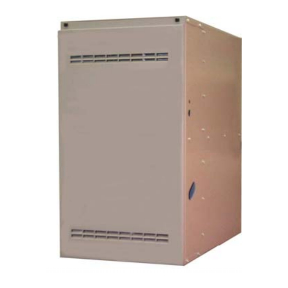
These compact units (31-1/2" high) employ induced combus-
tion, reliable electronic ignition and high heat transfer heat
exchangers. The units may be factory shipped for upflow/hor-
izontal application and converted for downflow application.
These units may also be factory shipped for downflow appli-
cation and converted for upflow/horizontal applications
Note: The 150 MBH input model is upflow/horizontal only and
may not be converted to the downflow position.
These furnaces are designed for residential installation in a
basement, closet, alcove, attic, or garage. All units are factory
assembled, wired and tested to assure safe dependable and
economical installation and operation.
These units are Category I listed and may be common vented
with another gas appliance as allowed by the National Fuel
Gas Code.
WARRANTY
20-year limited warranty on the heat exchanger.
5-year limited parts warranty.
FEATURES
• 4-position (MU) upflow models allow horizontal-left, hori-
zontal-right, downflow and convertible applications
• 4-position (MD) models allow downflow and convertible
upflow/horizontal applications
• 3-position (UH) 150 MBH input model allows upflow, hori-
zontal-left and horizontal-right application
• Reliable, hot surface ignitor
• Integrated control module for simplicity and reliable, eco-
nomical operation
• Built-in self-diagnostics with fault code display
• 100% shut off main gas valve for added safety
• Rollout safety control
• Low unit amp requirement for easy application
• High quality inducer motor for quiet operation
• 40 VA, fuse protected control transformer
• Terminals for controlling humidifiers and EAC's
• Easy to connect power and control wiring
• Efficiency ratings of 80 AFUE
• Cooling blower relay supplied for easy installation of add-
on cooling
• Blower off-delay for cooling SEER improvement
• Multi-speed PSC, direct-drive blower motors to match
cooling requirements
• Adjustable fan-off settings to eliminate "cold-blow"
• Compact 31-1/2-in height allows installation in small space
confines
• All models are propane convertible with factory kit
• Pre-painted exterior provides attractive, durable finish
• Models are not approved for LoNox applications
270844-YTG-A-0407
Advertisement
Table of Contents

Summary of Contents for York G8C05012(MU,MD)B12
- Page 1 270844-YTG-A-0407 DESCRIPTION ® These compact units (31-1/2" high) employ induced combus- tion, reliable electronic ignition and high heat transfer heat exchangers. The units may be factory shipped for upflow/hor- izontal application and converted for downflow application. These units may also be factory shipped for downflow appli- cation and converted for upflow/horizontal applications Note: The 150 MBH input model is upflow/horizontal only and may not be converted to the downflow position.
-
Page 2: Cabinet And Duct Dimensions
F(in.) G(in.) H(in.) J(in.) K Vent (in.) 1200 17 1/2 16 1/2 20 3/8 20.0 14 3/4 18 3/4 15 1/8 19.0 G8C05012(MU,MD)B12 1200 17 1/2 16 1/2 20 3/8 20.0 14 3/4 18 3/4 15 1/8 19.0 G8C07512(MU,MD)B12 1600 20 3/8 20.0... -
Page 3: Ratings & Physical / Electrical Data - Upflow Models
270844-YTG-A-0407 RATINGS & PHYSICAL / ELECTRICAL DATA - UPFLOW MODELS Total Air Temp. Input Output Nominal Airflow Cabinet Width Unit Rise Models AFUE Amps °F G8C05012(MU,MD)B12 1200 17-1/2 80.0 30-60 G8C07512(MU,MD)B12 1200 17-1/2 80.0 35-65 G8C07516(MU,MD)C12 1600 11.4 80.0 30-60... -
Page 4: Blower Performance
Cabinet Speed Input Size UPFLOW, SINGLE SIDE RETURN (WITHOUT FILTER) High 1411 1360 1289 1218 1154 1075 1213 1177 1134 1085 1022 G8C05012(MU,MD)B12 High 1535 1470 1408 1343 1275 1202 1115 1014 1215 1199 1182 1151 1106 1039 G8C07512(MU,MD)B12 High... -
Page 5: Return Air And Filters
External Static Pressure, Inches WC - CFM BTU/H (kW) Cabinet Speed Input Size BOTTOM/END RETURN High 1419 1357 1297 1212 1131 1050 1221 1185 1145 1092 1036 G8C05012(MU,MD)B12 High 1552 1491 1420 1348 1271 1185 1080 1229 1237 1198 1164 1105 1039 G8C07512(MU,MD)B12 High 1946 1862... -
Page 6: Filter Performance - Pressure Drop Inches W.c. And (Kpa)
270844-YTG-A-0407 RECOMMENDED FILTER SIZE UPFLOW Side Bottom/End Input Air Flow Cabinet Return Return Models Size G8C05012(MU,MD)B12 1200 25 x 16 25 x 16 G8C07512(MU,MD)B12 1200 25 x 16 25 x 16 G8C07516(MU,MD)C12 1600 25 x 16 25 x 20 G8C10016(MU,MD)C12... -
Page 7: Applying Filter Pressure Drop To Determine System Airflow
270844-YTG-A-0407 APPLYING FILTER PRESSURE DROP TO Example: For a 75,000 BTUH furnace with 2 return openings DETERMINE SYSTEM AIRFLOW and operating on high-speed blower, it is found that total sys- tem static is 0.38” w.c. To determine the system airflow, com- To determine the approximate airflow of the unit with a filter in plete the following steps: place, follow the steps below:... - Page 8 NOTES Subject to change without notice. Printed in U.S.A. 270844-YTG-A-0407 Copyright © by York International Corp. 2007. All rights reserved. Supersedes: 246657-YTG-C-0806 Unitary 5005 Norman Products York Group Drive 73069...


