Icom IC-A200 Service Manual
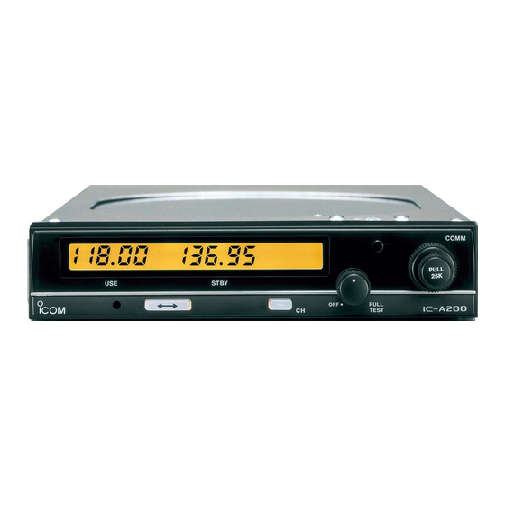
Vhf air band transceiver
Hide thumbs
Also See for IC-A200:
- Service manual (39 pages) ,
- Instruction manual (16 pages) ,
- Installation instructions manual (9 pages)
Table of Contents
Advertisement
Advertisement
Table of Contents

Related Manuals for Icom IC-A200


Summary of Contents for Icom IC-A200
- Page 1 ������� ������ VHF AIR BAND TRANSCEIVER iC-a200 S-14227MZ-C1 Apr. 2006...
- Page 2 8. READ the instructions of test equipment thoroughly before connecting equipment to the transceiver. Icom, Icom Inc. and logo are registered trademarks of Icom Incorporated (Japan) in the United States, the United Kingdom, Germany, France, Spain, Russia and/or other countries.
-
Page 3: Table Of Contents
TABLE OF CONTENTS SECTION 1 SPECIFICATIONS SECTION 2 INSIDE VIEWS SECTION 3 CIRCUIT DESCRIPTION 3 - 1 RECEIVER CIRCUITS ....................3 - 1 3 - 2 TRANSMITTER CIRCUITS ..................... 3 - 3 3 - 3 PLL CIRCUITS ........................ 3 - 4 3 - 4 VOLTAGE LINES ...................... -
Page 4: Specifications
SECTION 1 SPECIFICATIONS GENERAL • Frequency range : 118.000–136.975 MHz • Mode : AM (6K00A3E) • Tuning steps : 25 kHz, 50 kHz or 1 MHz • Number of memory channels • Frequency stability : ±0.0015% (–20°C to +55°C) : 50 Ω... -
Page 5: Inside Views
SECTION 2 INSIDE VIEWS ���� ���� ��������� ��������� ������� � � ��������� ������ ������������ ������ �������� ��� ��������� ������� ��������� ������� ���� ������� ����� ����������� ��� ����� ��� �� ���� ������ �������� ���������� ��� ����� ������������ ��� ���� ������ ��� ���� �����... -
Page 6: Circuit Description
SECTION 3 CIRCUIT DESCRIPTION 3-1 RECEIVER CIRCUITS 3-1-3 1st MIXER AND 1st IF CIRCUITS (MAIN UNIT) 3-1-1 ANTENNA SWITCHING CIRCUIT (PA UNIT) The 1st mixer circuit converts the received signals to a fixed The antenna switching circuit functions as a low-pass filter frequency of the 1st IF signal using a PLL output frequency. - Page 7 3-1-5 AM DETECTOR CIRCUIT (MAIN UNIT) 3-1-7 SQUELCH CIRCUIT (MAIN UNIT) The AM detector circuit demodulates the 2nd IF signal to The squelch circuit cuts out AF signals when receiving no AF signals. modulated signal. When no voice modulation is included in the signal, the squelch circuit cuts out the AF signal by The 2nd IF signal from Q10 is detected at the AM comparing voice audio and noise audio components in the...
-
Page 8: Transmitter Circuits
3-2 TRANSMITTER CIRCUITS The PLL output and the reference oscillator signals are amplified at Q29 and Q20 respectively and are then applied 3-2-1 MIC AMPLIFIER CIRCUIT (MAIN UNIT) to the transmitter mixer circuit (IC15). The mixed signal The mic amplifier circuit amplifies the mic audio with the is passed through the transmitter bandpass filter to re limiter circuit to a level needed for the AM modulator. -
Page 9: Pll Circuits
3-3 PLL CIRCUITS The VCO circuits (Q2004) employs a clap oscillator circuit. The signal generated at the VCO is buffer-amplified at 3-3-1 GENERAL (PLL UNIT) Q2001 or Q2002. The amplified signals are used for a The PLL circuit steadily oscillates the transmit and receive receive/transmit LO signal as PLL output (OUT2) or used local frequencies while comparing the phase of the divided for a feedback signal (OUT1) to the PLL circuit. -
Page 10: Voltage Lines
3-4 VOLTAGE LINES 3-5 CPU PORT ALLOCATIONS LINE DESCRIPTION Pin No. Port No. Description A voltage line from the external DC power Input port for the frequency exchange connector. switch. Input port for the channel switch. Used for the transmitter circuit. Produced by the T8V regulator (Q34, Q35, D32) Input port for tuning step selection and controlled by the T/R switching circuit... -
Page 11: Memory Protection
SECTION 4 MEMORY PROTECTION To prevent accidental changes, required memory channels 7) Push [ can be specified as protect channels. The contents of protect channels CANNOT be changed by a user. � � 4-1 MEMORY PROTECTION PROGRAMMING 8) Unground the memory protection pin. •... -
Page 12: Connections
SECTION 5 CONNECTIONS 5-1 WIRING CONNECTION ����� ��������� � � �� ����� �������� ���� � � ���� � � ���� ����� ����� ���� � � ����� ������ � � � � � � ��� � ��������� ���� � � ������������ ������ ���... -
Page 13: Molex Connector
For the memory channel switch and frequency exchange switch, use a 2-position rocker switch or 2 separate The IC-A200 has a 5 A internal fuse. If the power does not momentary push switches. turn ON, open the top cover and check the fuse. -
Page 14: Rack Mount Assembly
5-3 RACK MOUNT ASSEMBLY ������������� ��� ������� ����� ���� ��� ��� �������� ������ ������� ��������� �������� ���� ����� �������� ������� ����� ����� ���� ����� ��������� ������ ����� ��������� 5 - 3... -
Page 15: Adjustment Procedures
SECTION 6 ADJUSTMENT PROCEDURES 6-1 PREPARATION BEFORE SERVICING REQUIRED TEST EQUIPMENTS EQUIPMENT GRADE AND RANGE EQUIPMENT GRADE AND RANGE Output voltage : 13.2 V DC Oscilloscope Frequency range : DC–20 MHz DC power supply Current capacity : 2 A or more DC voltmeter Input impedance : 50 kΩ/DC or better... -
Page 16: Pll Adjustment
6-2 PLL ADJUSTMENT ADJUSTMENT MEASUREMENT POINT ADJUSTMENT ADJUSTMENT CONDITIONS VALUE UNIT LOCATION UNIT ADJUST REFERENCE 1 • Frequency display: 118.000 MHz MAIN Connect the frequency 32.000000 MHz MAIN C199 OSCILLATOR • Receiving counter to J31. LOCK 1 • Frequency display: 118.000 MHz MAIN Connect the DC voltmeter 2 V ±0.1 V C2015... - Page 17 ��� ����� ���� ���������� �� �� �������� ������ �� ���������� ��� ��� �� ��� ������� ���������� ��� �� ��� ���� ���������� ���� ��� ��� ���������� ��� ��� ��� �� ����� ��� ���������� ��� ��� �� ����� ����������� ����� ��������� ���������� ����...
-
Page 18: Transmitter Adjustment
6-4 TRANSMITTER ADJUSTMENT ADJUSTMENT MEASUREMENT ADJUSTMENT ADJUSTMENT CONDITIONS VALUE POINT UNIT LOCATION UNIT ADJUST IDLING 1 • Disconnect P3 Connect the DC ammeter 150 mA R5005 CURRENT • Unsolder C.P. + and C.P. –. (1 A) to point between • Frequency display : 127.000 MHz C.P.+ and C.P.–. - Page 19 ����� ���������� ���������� ������� ����� �� ��� ������ ����� ����� ����� ������ �� ������ ������� ����� ������ ����� ������ ������� ����������� ����� ���� ���������� ����������� ���� ��� ������� ��� �������� ������ ����������� ��� ����� ��� ����� �� �������� ������ ������ ����� �����...
-
Page 20: Mechanical Parts And Disassembly
SECTION 7 MECHANICAL PARTS AND DISASSEMBLY 7-1 MECHANICAL PARTS LABEL LABEL ORDER NO. DESCRIPTION QTY. ORDER NO. DESCRIPTION QTY. NUMBER NUMBER 8210006550 867 Front panel 8930022671 867 F shield plate 8930022660 867 R shield plate 8610007601 Knob N174(A)-1 8010001170 Knob cover for N174/(A) 8010011710 867 PA cover 8610007613 Knob N175-3 8610007630 Knob K182... - Page 21 6510013840 Connector 4338-15 6510013850 Pin 4366-GL 8810007070 Screw Bind UNC No. 4 × 12.7 6510014200 Connector BNC-LP ���� ���� 8850001210 ICOM washer (V) 8860000720 C ring-S 8950002550 Nylon clip SL-9N 8830000740 Nut UNC No. 6 8830000750 Nylon nut UNC No. 6 8810007080 Screw BiH UNC No.
-
Page 22: Parts List
SECTION 8 PARTS LIST [MAIN UNIT] [MAIN UNIT] ORDER ORDER DESCRIPTION DESCRIPTION 1110002550 IC TA7252AP 6140001200 COL LR-145 1120002900 S.IC M5223AFP 6110002000 COL LA-226 1140009120 S.IC µPD750004GB-F10-3BS-MTX 6110001670 COL LA-253 1130012670 S.IC BR93L46F 6140002060 COL LR-225 (RIB3X6.5X3 3A6) 1110005711 S.IC S-80842CLUA-B63 G 6140002060 COL LR-225 (RIB3X6.5X3 3A6) - Page 23 [MAIN UNIT] [MAIN UNIT] ORDER ORDER DESCRIPTION DESCRIPTION R108 7030003540 S.RES 6.8K ERJ3GE R234 7030003640 S.RES 47K ERJ3GE R109 7030003540 S.RES 6.8K ERJ3GE R235 7030003640 S.RES 47K ERJ3GE R110 7030003440 S.RES 1K ERJ3GE R236 7030003640 S.RES 47K ERJ3GE R111 7030003440 S.RES 1K ERJ3GE R237 7030003640 S.RES...
- Page 24 [MAIN UNIT] [MAIN UNIT] ORDER ORDER DESCRIPTION DESCRIPTION R369 7030003610 S.RES 27K ERJ3GE C125 4030006880 S.CER 0.0047 C1608 B R370 7030003440 S.RES 1K ERJ3GE C127 4030006880 S.CER 0.0047 C1608 B R371 7030003480 S.RES 2.2K ERJ3GE C129 4030006800 S.CER 220P C1608 R372 7030003580 S.RES 15K ERJ3GE...
-
Page 25: Pll Unit
[MAIN UNIT] [PLL UNIT] ORDER ORDER DESCRIPTION DESCRIPTION 6510003430 CNR B07B-EH-S C1007 4030004720 S.CER 0.001 C2012 B 6510003420 CNR B06B-EH-S C1008 4510008490 S.ELE 10 16V EEE-S A 6510010020 CNR RTB-1.5-2F C1009 4550000560 S.TAN 0.33 35V SVA 6910001040 CNR IPS-1136 C1010 4030004710 S.CER 470P C2012 B 6510007020 CNR... -
Page 26: Front Unit
[DIAL UNIT] [PA UNIT] ORDER ORDER DESCRIPTION DESCRIPTION S3001 2260001620 SW SW-133 (RK09720HM) R5021 7010004070 RES R20J 100 R5022 7010004110 RES R20J 220 R5023 7010004070 RES R20J 100 R5024 7070000210 RES CRH100X R-02J 47 C5001 4010006280 CER HE50SJ SL 101J 50V C5002 4010006060 CER HE40SJ SL 100D 50V... - Page 27 [CHASSIS PARTS] ORDER DESCRIPTION D6001 1710000010 DIO 15CD11 J6001 6510014210 CNR BNC-BJ M.=Mounted side (T: Mounted on the Top side, B: Mounted on the Bottom side) S.=Surface mount 8 - 6...
- Page 28 The combination of this page and the next page shows SECTION 9 BOARD LAYOUTS the unit layout in the same configuration as the actual P.C. Board. �������� ������� ������� ���� ���� ��� �� ���� ��� � � � � � �...
- Page 29 The combination of this page and the previous page shows the unit layout in the same configuration as the actual P.C. Board. ��������� ���� ���� ���� ���� �������� ��������� �������� ������� � ������� ���� ���� ���� ���� ��� ��� �� ���...
- Page 30 The combination of this page and the next page shows the unit layout in the same configuration as the actual P.C. Board. ��� ����� ���� ���� ����� ����� ��� ������ �� ���� ��������� ���� ������ �� ��� ���� ��� ��� ������ ���� ������� ��...
- Page 31 The combination of this page and the previous page shows the unit layout in the same configuration as the actual P.C. Board. ����� ���� ������� ����� ��� ��� ��� ��� ��� ��� ����� ��� ������ �� ���� ��������� ���� ������ �� ��� ���� ��� ��� ������ ���� ������� ��...
- Page 32 The combination of this page and the next page shows the unit layout in the same configuration as the actual P.C. Board. ��� ��� ���� ���� ����� ��������� ������� ����� ����� � � � � � � ������� �� ������� �� ���������...
- Page 33 The combination of this page and the previous page shows the unit layout in the same configuration as the actual P.C. Board. ��� ���� ������� ����� ��� ���� ������� ����� 9 - 6...
-
Page 34: Block Diagram
SECTION 10 BLOCK DIAGRAM ��� ������� ���� ������� ���� ������� ��� ��� ��� �� ���� ��� ��� ��� ��� ��� ��� ��� ��� ���� ��� ��� ����� ������ ������ ������ ������ ������� ������ ������� ���������� ��� ��� ������� ��� ��� ���... -
Page 35: Voltage Diagram
SECTION 11 VOLTAGE DIAGRAM �� ���� ���� �� �� ����� ��������������� ����� ����� ����� ���� ������ ���� ����� ����� ��� ���� ��� �� ���� ������ ����� ����������� ��� ���� ��� ���� ����� ����� ��� �� ��� �� ��� ��� ��� ���� �����... - Page 36 ��� ��� ������������� ����� ��� ��� ��� ����� �� �� �� �� �� �� ��� ��� ��� ���� ������ ������ ������ �� ������� ������ ������ ��� ��� ��� ��� ��� �������� ��� ���� �� �� �� ��� ��� �� ������ ���...
- Page 37 ������� ����������� ���������� ����� ��������� ����� ����� � ��� ���� ���� ���� ��� � ��� ���� ���� ���� ��� � �������������������������������������� ���������� ������������� ������������� ��������� ���� ����� ������ ����� ��������� �� ������ ������ ������������� ���� ���� ������� ����������� ������� ����� � �� ����� �������� ���...
- Page 38 S-14227MZ-C1 1-1-32, Kamiminami, Hirano-ku, Osaka 547-0003, Japan © 2006 Icom Inc.