Table of Contents
Advertisement
Quick Links
Advertisement
Table of Contents

Related Manuals for Furuno DFF1-UHD


Summary of Contents for Furuno DFF1-UHD
-
Page 1: Network Fish Finder
OPERATOR'S MANUAL NETWORK FISH FINDER DFF1-UHD Model www.furuno.com... - Page 3 How to discard a used battery Some FURUNO products have a battery(ies). To see if your product has a battery, see the chapter on Maintenance. Follow the instructions below if a battery is used. Tape the + and - terminals of battery before disposal to prevent fire, heat generation caused by short circuit.
- Page 4 A warning label is attached to the equipment. Do not remove this label. If the label is missing Turn off the power immediately if you or illegible, contact a FURUNO agent or dealer feel the equipment is acting abnormally. about replacement.
- Page 5 SAFETY INSTRUCTIONS Safety instructions for the installer WARNING CAUTION CAUTION The transducer cable must be handled Do not open the equipment. carefully, following the guidelines below. Only qualified personnel should work inside the equipment. • Keep fuels and oils away from the cable.
-
Page 6: Table Of Contents
TABLE OF CONTENTS FOREWORD ........................v SYSTEM CONFIGURATION ..................vi INSTALLATION ......................1 1.1 Equipment Lists......................1 1.2 Network Fish Finder ...................... 2 1.3 Transducer ........................3 1.4 Optional Speed/Temperature Sensors ST-02MSB, ST-02PSB ........3 1.4.1 Mounting considerations..................3 1.4.2 Mounting procedure....................3 1.5 Optional Temperature Sensors .................. -
Page 7: Foreword
Thank you for considering and purchasing FURUNO. Features The DFF1-UHD is a dual frequency echo sounder designed for use with the NavNet TZtouch se- ries. The DFF1-UHD feeds data about underwater conditions via a LAN. • FURUNO TruEcho CHIRP fishfinders provide very high definition images. -
Page 8: System Configuration
SYSTEM CONFIGURATION NavNet Equipment TZT9/14/BB Ethernet HUB HUB-101 NETWORK FISH FINDER DFF1-UHD 12-24 VDC Rectifier PR-62 External Speed/Temperature Sensor ST-02MSB ST-02PSB 100/110/ 220/230 VAC Temperature Sensor Transducer 1ø, 50/60 Hz T-02MTB T-02MSB B265LH or T-03MSB CM265 LH... -
Page 9: Installation
INSTALLATION Equipment Lists Standard supply Name Type Code No. Remarks Network Fish Finder DFF1-UHD — Spare Parts SP02-05601 001-033-740 1 set Fuse (2 pcs.) Installation Materials CP02-08500 000-011-917 1 set - Power cable assy. (3.5 m) - LAN cable assy. (5 m) -
Page 10: Network Fish Finder
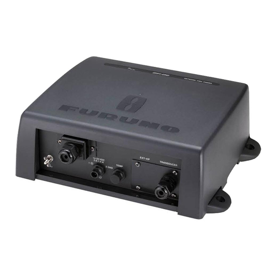
1. INSTALLATION Network Fish Finder The network fish finder can be installed on a desktop, deck or on a bulkhead. When selecting a mounting location, keep the following points in mind: • The temperature and humidity at the mounting site should be moderate and stable. •... -
Page 11: Transducer
1. INSTALLATION Transducer The performance of the fish finder largely depends upon the transducer position. Select a place least affected by air bubbles since turbulence blocks the sounding path. The face of the transducer must be facing the sea bottom in normal cruising trim of the boat. Further, select a place least in- fluenced by engine noise. -
Page 12: Optional Temperature Sensors
1. INSTALLATION Optional Temperature Sensors 1.5.1 Transom mount temperature sensor T-02MTB • Fix the cable at a convenient location with cable clamp. • When the cable is led in through the transom board, make a hole of approx. 17 mm in diameter to pass the connector. -
Page 13: Thru-Hull Temperature Sensor T-02Msb, T-03Msb
1. INSTALLATION 1.5.2 Thru-hull temperature sensor T-02MSB, T-03MSB Select a suitable mounting location considering the following points. • Select a mid-boat flat position. The sensor does not have to be installed perfectly perpendicular. However, the location should not be such that the transducer may be damaged when the boat is dry-docked. -
Page 14: Wiring
Connect the power cable, transducer cables, sensor cable, network cable and ground wire to their respective locations on the network sounder. See the next page for how to connect the transducer cables. TZT9/TZT14/ TZTBB To HUB-101 MOD-Z072-050+, 5 m (option: 2/10 m) DFF1-UHD EXT-KP TRANSDUCER 12-24 VDC TEMP 2.8-1.4 A MJ-A3SPF0013-035C External (3.5 m) -
Page 15: Transducer Cable, Cable For External Kp (Option)
2. WIRING Transducer Cable, Cable for External KP (option) If the external KP is not to be connected, do only the applicable procedures in sections 2.2.1 and 2.2.2. The KP from an echo sounder or sonar can be connected to this network fish finder to synchronize transmission (to prevent interference). - Page 16 2. WIRING How to process the cable for the external KP 1. Process the PH connector (02-1097, optional supply) as shown below. a) Make the length of the wires of the PH connector 100 mm. b) Remove the sheath from the cores 10 mm. c) Fold back the cores in half.
-
Page 17: How To Connect The Transducer Cable
2. WIRING 2.2.2 How to connect the transducer cable This procedure shows you how to connect the transducer cable. To connect both the transducer cable and the cable for external KP, go to section 2.2.3. 1. Open the cover: Grasp the cover at two sides, spread the cover slightly and lift. 2. - Page 18 2. WIRING 5. Loosen the two screws fixing the clamp fixing plate to detach the plate. Clamp fixing plate 6. Pass the sealing nut (unfastened at step 4) onto the transducer cable and pass the cable through the super gland and into the unit. 7.
-
Page 19: How To Connect The Cable For External Kp, Transducer Cable
2. WIRING 10. Tighten the sealing nut according to the information in the table below. Transducer Clearance Torque CM265LH 4 mm 1.8 - 2.0N/m B265LH 2 mm Clearance 11. Reattach the shield cover and close the outer cover. 2.2.3 How to connect the transducer cable, cable for external KP 1. - Page 20 2. WIRING 6. Unfasten the nut material inside the unit. Nut material Clamp fixing plate Clamp Rainproofing panel 7. Using the two screws removed at step 5, fasten the upper two holes of the supplied rainproof- ing panel. Fasten upper two holes Rainproofing panel (supplied)
- Page 21 2. WIRING 8. TIghten the lock nut inside the unit to fasten the super glands (two pcs., see step 12). The torque for the lock nut shall be 1.8 - 2.0 N/m. Super gland (two pcs.) 9. Set the nut material (removed at step 6) inside the unit, align its two protrusions with the lower holes on the rainproofing panel.
- Page 22 2. WIRING 11. For the transducer cable and the cable for the external KP, pass each cable through its super gland, the supplied rainproofing panel and each hole in the unit. Then slip a lock nut onto each cable. (For the super gland of the cable for the external KP, unfasten the lock nut from the super gland then pass the cable through the super gland.
- Page 23 2. WIRING 12. Transducer cable: Lay the transducer cable in the cable clamp then refasten the clamp fixing plate. Cable for the external KP: Lay the cable in the cable clamp and fix it with the supplied clamp fixing plate and two upset screws. Lock nut for super gland (2 pcs.) Clamp fixing plate Large: transducer cable...
- Page 24 2. WIRING 14. Attach the supplied EMI core (GRFC-10) to the cable for the external KP approx. 100 mm from the super gland. 10 mm Super gland (for ext. KP) EMI core 15. Attach the shield cover and close the outer cover.
-
Page 25: Lan Cable
2. WIRING LAN Cable Do as follows to connect the supplied LAN cable (MOD-Z072-050+) or the optional LAN cable (MOD-Z072-020+, MOD-Z072-100+). 1. Unfasten the sealing nut from the LAN connector then remove the sealing insert and clamping claw. 2. Detach the sealing insert from the clamping claw as shown below. Seal assy. - Page 26 2. WIRING 3. Pass the sealing nut, clamping claw and sealing insert onto the LAN cable in the order shown in the figure below. Connect the cable to the LAN connector. (Note the orientation of the seal- ing insert when passing it onto the cable. Push the cable into the slit in the sealing insert.) LAN cable Sealing insert (Push cable into slit.)
-
Page 27: Initial Settings
INITIAL SETTINGS WARNING Do not open the equipment unless totally familiar with electrical circuits. Only qualified personnel should work inside the equipment. DIP Switch Setting The DIP switch S2 sets up the system according to the equipment connected. In the default setting all switches (1-8) are OFF. -
Page 28: Operation Check
For NavNet TZtouch, the DFF1-UHD is powered on/off from ship’s switchboard. For NavNet 3D, it is powered on/off from the display unit. The LED on the cover of the DFF1-UHD lights or blinks according to equipment state, as described in the table below. -
Page 29: Maintenance
MAINTENANCE NOTICE WARNING Do not apply paint, anti-corrosive sealant or ELECTRICAL SHOCK HAZARD Do not open the equipment. contact spray to coating or plastic parts of the equipment. Only qualified personnel should work inside the Those items contain organic solvents that can equipment. -
Page 30: How To Replace The Fuse
#4: Restore all default settings. Use this when changing transducers. 3. Connect the power cable to the DFF1-UHD, and turn on the power at the ship’s switchboard. 4. The LED blinks (every 0.4 seconds) when default settings are completely restored. -
Page 31: Appendix 1 Jis Cable Guide
EX: DPYCYSLA - 1.5 MPYC - 4 TTYCSLA-4 Core Area (mm Designation type Designation type # of cores The following reference table lists gives the measurements of JIS cables commonly used with Furuno products: Core Cable Core Cable Diameter Diameter... -
Page 32: Specifications
FURUNO DFF1-UHD SPECIFICATIONS OF NETWORK FISH FINDER DFF1-UHD GENERAL TX frequency 50/200 kHz, alternative transmission Output power 1 kW nominal Amplifier type Straight amplifier (H/L gain switching available) Depth range and Pulse repetition rate (PRR) at 200 kHz, TX rate: 20 Range (m) PRR (times/min, max.) -
Page 33: Packing List
PACKING LIST 02GL-X-9851 -0 DFF1-UHD N A M E DESCRIPTION/CODE № O U T L I N E Q'TY ユニット UNIT ネットワーク魚探 DFF1-UHD NETWORK FISH FINDER 000-022-520-00 予備品 SPARE PARTS SP02-05601 ヒューズ FGB0-A 125V 5A PBF GLASS TUBE FUSE 000-155-853-10 工事材料... - Page 36 When a claim is made, FURUNO has a right to choose whether with other electronic devices. The imported product may also be to repair the product or replace it.
- Page 37 24 months from installation date provided the work is done by Furuno U.S.A., Inc. or an AUTHORIZED Furuno dealer during normal shop hours and within a radius of 50 miles of the shop location.
- Page 40 (Elemental Chlorine Free) The paper used in this manual is elemental chlorine free. FURUNO Authorized Distributor/Dealer 9-52, Ashihara-cho, Nishinomiya, 662-8580, JAPAN A: JAN. 2013 Printed in Japan All rights reserved. B: JAN. 31, 2013 Pub. No. OME-20400-B (DAMI) DFF1-UHD...