Table of Contents
Advertisement
Quick Links
Advertisement
Table of Contents

Related Manuals for Miele S 247i


Summary of Contents for Miele S 247i
- Page 1 TECHNICAL INFORMATION S 2xx, S 3xx and S 4xx Canister Vacuums 2012 Miele USA ©...
-
Page 2: Table Of Contents
S 4xx Components ....................14 1.2 Features ......................15 1.3 Technical Data ....................18 1.3.1 S 247i - S 256i ...................... 18 1.3.2 S 269i - S 282i ...................... 18 1.3.3 S 3xx ........................19 ... - Page 3 S 2xx, S 3xx & S 4xx Canister Vacuums Technical Information 5.4.2 S 27x ........................31 5.4.3 S 3xx and S 4xx ....................31 5.5 Dustbag Change Indicator .................. 31 5.5.1 S 25x ........................31 ...
- Page 4 6.8 Motor Does Not Operate (S 345i and S 445i) ............. 60 List of Figures Figure 1-1: S 247i, S 248i ....................8 Figure 1-2: S 249i, S 250i ....................8 Figure 1-3: S 251i, S 252i ....................8 Figure 1-4: S 254i ....................... 8 ...
- Page 5 S 2xx, S 3xx & S 4xx Canister Vacuums Technical Information Figure 1-22: S 421i, S 422i, S 424i, S 426i ..............11 Figure 1-23: S 434i, S 436i, S 438i ................... 12 Figure 1-24: S 442i ......................12 Figure 1-25: S 444i ......................12 Figure 1-26: S 446i, S 447i, S 448i ...................
- Page 6 S 2xx, S 3xx & S 4xx Canister Vacuums Technical Information Figure 5-37: S 254i and S 255i Suction Hose with Integrated Wiring ....... 52 Figure 5-38: S 270i - S 276i, S 280i Suction Hose with Integrated Wiring ....... 53 Figure 5-39: S 278i Suction Hose with Integrated Wiring ..........
-
Page 7: Construction And Design
S 2xx, S 3xx & S 4xx Canister Vacuums Technical Information Construction and Design General Information All repairs should be performed by a trained technician in strict accordance with national, state and local codes. Any repairs or maintenance performed by unqualified personnel could be dangerous. When servicing, modifying, testing or maintaining appliances, all applicable laws, regulations and accident prevention guidelines must be observed. -
Page 8: Figure 1-1: S 247I, S 248I
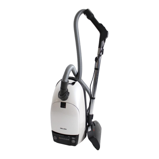
S 2xx, S 3xx & S 4xx Canister Vacuums Technical Information Figure 1-1: S 247i, S 248i Figure 1-2: S 249i, S 250i Figure 1-3: S 251i, S 252i Figure 1-4: S 254i Figure 1-5: S 255i, S 256i... -
Page 9: Figure 1-6: S 234I
S 2xx, S 3xx & S 4xx Canister Vacuums Technical Information Figure 1-6: S 234i Figure 1-7: S 269i, S 270i Figure 1-8: S 271i, S 272i Figure 1-9: S 274i Figure 1-10: S 275i, S 276i Figure 1-11: S 278i... -
Page 10: Figure 1-12: S 280I, S 282I
S 2xx, S 3xx & S 4xx Canister Vacuums Technical Information Figure 1-12: S 280i, S 282i Figure 1-13: S 300i, S 301i Figure 1-14: S 310i, S 313i Figure 1-15: S 321i, S 324i, S326i Figure 1-16: S 334i, S 336i, S 338i... -
Page 11: Figure 1-17: S 342I
S 2xx, S 3xx & S 4xx Canister Vacuums Technical Information Figure 1-17: S 342i Figure 1-18: S 344i Figure 1-19: S 346i, S 347i, S 348i Figure 1-20: S 400i, S 401i, S 402i, S 408i Figure 1-21: S 410i Figure 1-22: S 421i, S 422i, S 424i, S 426i... -
Page 12: Type/Construction
S 2xx, S 3xx & S 4xx Canister Vacuums Technical Information Figure 1-23: S 434i, S 436i, S 438i Figure 1-24: S 442i Figure 1-25: S 444i Figure 1-26: S 446i, S 447i, S 448i Type/Construction Canister vacuum cleaner. 1.1.1 S 3xx Components... -
Page 13: Figure 1-27: S 3Xx Components
S 2xx, S 3xx & S 4xx Canister Vacuums Technical Information Figure 1-27: S 3xx Components These vacuum cleaners consist of 4 main parts: 1) Switch unit − Suction power selector or electronic, depending on model − “On/Off” switch − Overheating warning light, depending on model −... -
Page 14: S 4Xx Components
S 2xx, S 3xx & S 4xx Canister Vacuums Technical Information 1.1.2 S 4xx Components Figure 1-28: S 4xx Components 1) Integrated in rear casing − Foot switch unit − Suction power selector on top − Cable rewind − Motor 2) Integrated in dustbag compartment casing −... -
Page 15: Features
S 2xx, S 3xx & S 4xx Canister Vacuums Technical Information Features Model S 247i, S 248i S 249i, S 250i S 251i, S 252i S 254i S 255i, S 256i Dustbag change indicator Automatic cord rewind Electric brush socket... - Page 16 S 2xx, S 3xx & S 4xx Canister Vacuums Technical Information Model S 300i S 301i S 310i S 313i S 321i S 324i S 326i S-Class filter Auto-reverse cord rewind Electrobrush socket Overheating warning light Blower Separate connection Radius of operation Dustbag capacity...
- Page 17 S 2xx, S 3xx & S 4xx Canister Vacuums Technical Information Model S 334i S 336i S 338i S 342i S 344i S 346i S 347i S 348i Dustbag capacity Fuse rating 10A, slow-trip switch Protection Class II, double-insulated classification Model S 401i S 408i...
-
Page 18: Technical Data
Separate Separate connection Radius of operation x = Standard o = Optional Stainless-steel telescopic suction tube Technical Data 1.3.1 S 247i - S 256i Suction pressure 240mbar Throughflow rate 56 L/sec Dustbag Two-ply paper bag Dustbag capacity Operational radius 9.5m Weight including accessories 7.9kg... -
Page 19: S 3Xx
S 2xx, S 3xx & S 4xx Canister Vacuums Technical Information 1.3.3 S 3xx S 3xx Booster Suction pressure 250mbar 275mbar Throughflow rate 67 L/sec 72 L/sec Dustbag capacity Operational radius Weight including 8 - 9 kg, depending on accessories model Electrical connection 230VAC 50Hz... -
Page 20: Accessories
S 2xx, S 3xx & S 4xx Canister Vacuums Technical Information Accessories 1.4.1 Standard Accessories S 247i - S 256i S 269i - S 282i S 3xx S 4xx Telescopic suction tube depends on depends on Telescopic or w/locking model... -
Page 21: Electrobrush Plug System (S 3Xx And S 4Xx Only)
S 2xx, S 3xx & S 4xx Canister Vacuums Technical Information Figure 1-31: 20cm Swivel Adapter Sleeve to Connect Lockable Accessories Electrobrush Plug System (S 3xx and S 4xx Only) Due to a change in the EN 60320 component legislation, the built-in socket and connection cable for the SEB 215 electrobrush have been modified with effect from March 1, 1998. -
Page 22: Active Air Clean Filter
S 2xx, S 3xx & S 4xx Canister Vacuums Technical Information 4.1.2 Active Air Clean Filter The Active Air Clean filter contains active charcoal and can be fitted to absorb odors from the exhaust air. 4.1.3 S-Class Filter The S-class filter is a particulate air filter and in many countries its fitting is a legal requirement when the vacuum cleaner is to be used in operating rooms or hospitals. -
Page 23: S 3Xx
S 2xx, S 3xx & S 4xx Canister Vacuums Technical Information 4.2.2 S 3xx Figure 4-1: S 3xx Dustbag Change Indicator The dustbag change indicator is incorporated in the dustbag compartment casing. The point at which the indicator shows that the dustbag should be changed is affected by the following: −... -
Page 24: S 4Xx
S 2xx, S 3xx & S 4xx Canister Vacuums Technical Information 4.2.3 S 4xx Figure 4-2: S 4xx Dustbag Change Indicator Depending on the dust quantity and type, and the hose attachment in use, the indicator shows when the dustbag should be changed. If flour or fine mineral dust is vacuumed, the indicator may show that the dustbag should be changed even if it is not full. -
Page 25: Power Regulation
S 2xx, S 3xx & S 4xx Canister Vacuums Technical Information dustbag compartment, so producing a negative pressure at the floor attachment. Air is then sucked into the appliance via the floor attachment and takes dirt and dust particles with it. Figure 4-3 is a simplified graph showing the relation between the two factors, negative pressure “h”... -
Page 26: Booster Setting
S 2xx, S 3xx & S 4xx Canister Vacuums Technical Information S 4xx series: Power control on automatic models is via a negative pressure switch combined with appropriate electronics. Laboratory experimentation has shown the optimum level of the ratio of suction power to electric power. -
Page 27: Phase-Chopping Control - Principle Of Operation
S 2xx, S 3xx & S 4xx Canister Vacuums Technical Information 4.4.4 Phase-Chopping Control - Principle of Operation Figure 4-4: Phase-Chopping Control α Phase angle Capacitor Trigger diode, here a diac Bi-directional thyristor, here a triac Potentiometer for setting the phase angle α Load, here the motor Triac, conductive View of half-wave:... -
Page 28: Dustbag Compartment Lid (And Hinges, If Applicable)
S 2xx, S 3xx & S 4xx Canister Vacuums Technical Information service work. Dustbag Compartment Lid (and Hinges, if Applicable) 5.1.1 S 25x 1. Open the dustbag compartment lid as far as possible, and then pull upwards to remove. 2. Release locking tabs, using a small flathead screwdriver if necessary. 5.1.2 S 27x 1. -
Page 29: Accessory Compartment Lid
S 2xx, S 3xx & S 4xx Canister Vacuums Technical Information Accessory Compartment Lid Open the accessory compartment lid and pull it upwards (using a suitable tool, if necessary) to remove it from the dust compartment lid. 5.2.1 Reassembly (S 2xx Only) 1. -
Page 30: S 3Xx
S 2xx, S 3xx & S 4xx Canister Vacuums Technical Information to remove it. 3. Re-install the holder (Figure 5-4, Item 1) as follows: a. Tighten screw (Figure 5-4, Item 2). b. Lightly install screw (Figure 5-4, Item 5) so that the holder (Figure 5-4, Item 1) can still be installed. -
Page 31: Dust Channel
S 2xx, S 3xx & S 4xx Canister Vacuums Technical Information 3. When re-installing, use pointed pliers to tension and hold the spring before pressing the holder into place. Dust Channel 5.4.1 S 25x 1. Open the dust compartment lid. 2. -
Page 32: S 3Xx
S 2xx, S 3xx & S 4xx Canister Vacuums Technical Information 3. Release the indicator from the lid. Note: Do not unscrew the lacquered screw as this is used to adjust the indicator. If the indicator needs to be dismantled then the indicator disc must first be turned to the right as far as possible. -
Page 33: S 3Xx
S 2xx, S 3xx & S 4xx Canister Vacuums Technical Information 3. Separate the complete cap assembly from the rear casing. Figure 5-8: S 27x Rear Casing 5.6.3 S 3xx 1. Remove the dustbag compartment lid (Section 5.1). 2. Remove the 2 Phillips screws securing the cap assembly to the base. 3. -
Page 34: Rear Casing
S 2xx, S 3xx & S 4xx Canister Vacuums Technical Information Rear Casing 5.7.1 S 25x 1. Remove the dust compartment lid, Section 5.1. 2. Unscrew the 3 Phillips screws (Figure 5-10, Item 1) to remove the rear casing (Figure 5-10, Item 3). 3. -
Page 35: S 4Xx
S 2xx, S 3xx & S 4xx Canister Vacuums Technical Information Figure 5-12: Rear Casing, S 3xx Note: Before re-installing the rear casing, make sure the gasket is in place! 5.7.4 S 4xx 1. Remove the cap assembly (Section 5.6). 2. -
Page 36: Foot Switches
S 2xx, S 3xx & S 4xx Canister Vacuums Technical Information Foot Switches 5.8.1 S 25x and S 27x 1. Remove suction power selector (S 27x only). 2. Press the locking tab (Figure 5-14, Item 1 or 2) down with a small screwdriver and slide out the appropriate foot switch. -
Page 37: Potentiometer/Suction Power Selector
S 2xx, S 3xx & S 4xx Canister Vacuums Technical Information Figure 5-16: Foot Switch, S 4xx Potentiometer/Suction Power Selector 5.9.1 S 2xx 2x1i & 2x2i: Remove the selector switch knob and change the potentiometer. 2x4i & 2x5i: 1. Release the catch (Figure 5-17, Item 2) with a small screwdriver and remove the switch cover (Figure 5-17, Item 1). -
Page 38: S 3Xx
S 2xx, S 3xx & S 4xx Canister Vacuums Technical Information Figure 5-17: Potentiometer Cover, S 2x4i and S 2x5i Figure 5-18: Catches on Potentiometer Control, S 2x4i and S 2x5i Figure 5-19: Potentiometer Control, S 2x4i and S 2x5i Important: Before replacing the complete potentiometer assembly (Figure 5-19, Item 3) and the indicator cylinder (Figure 5-19, Item 4), ensure the following:... -
Page 39: Figure 5-20: Rotary Potentiometer, S 3Xx
S 2xx, S 3xx & S 4xx Canister Vacuums Technical Information 1. Remove the cap assembly (Section 5.6). 2. Take off the rotary dial (pry off with a small screwdriver, if necessary). 3. Remove the Phillips screw. 4. Use a small screwdriver to release the spade connections from the white terminal block (mark/tag all connections before disconnecting them!). -
Page 40: S 4Xx
S 2xx, S 3xx & S 4xx Canister Vacuums Technical Information Figure 5-22: +/- Buttons, S 3xx Figure 5-23: Electronic +/- Buttons, S 3xx 5.9.3 S 4xx Rotary potentiometer: 1. Carefully ease off the switch knob using a lid opener, part no. 3051670. 2. -
Page 41: Figure 5-24: S 4Xx Slide Potentiometer
S 2xx, S 3xx & S 4xx Canister Vacuums Technical Information switch spindle to release the switch. Slide potentiometer: 1. Remove the foot switch assembly (Section 5.8). 2. Set the slide potentiometer to 300W. 3. Remove the group plug (Figure 5-24, Item 2) from the underside. Take care to note its positioning. -
Page 42: Electronic (S 4Xx Only)
S 2xx, S 3xx & S 4xx Canister Vacuums Technical Information Figure 5-25: Foot-Operated Power Selector, S 4xx Note: Before re-installing, ensure that the flattened shaft side of the cog drive (Figure 5-25, Item 3) is vertical and at the front, and that the indicator cylinder shows the lowest setting. -
Page 43: Fault/Overheat Indicator Lamp
S 2xx, S 3xx & S 4xx Canister Vacuums Technical Information Figure 5-26: S 4xx Electronic Removal 5.11 Fault/Overheat Indicator Lamp 5.11.1 S 2xx Remove the foot switch assembly (Section 5.8). The indicator lamp(s) should always be pushed out from below as they are clipped into place. 5.11.2 S 4xx The lamp can be removed from below by gently pulling its connection wires. -
Page 44: On/Off Switch
S 2xx, S 3xx & S 4xx Canister Vacuums Technical Information 5.12.2 S 27x 1. Remove the mounting panel and cap assembly (Section 5.6). 2. Release the retaining clips (Figure 5-27, Item 1) and remove the plug housing. Figure 5-27: S 27x Plug Housing 5.13 On/Off Switch 5.13.1... -
Page 45: Sensor (Automatic Models S 280I - S 282I)
S 2xx, S 3xx & S 4xx Canister Vacuums Technical Information Note: With models S 280i and S 282i (Automatic) the sensor, Figure 5-27, Item 1, must first be removed (see Section 5.15). 5.15 Sensor (Automatic Models S 280i - S 282i) 1. -
Page 46: S 3Xx
S 2xx, S 3xx & S 4xx Canister Vacuums Technical Information Figure 5-29: Cap Assembly with Lug, S 25x Models Figure 5-30: Brake Lever Top Edge, S 25x Models 5.16.3 S 27x 1. Dismantle the mounting panel and remove the reel retaining screws. 2. -
Page 47: Power Cord
S 2xx, S 3xx & S 4xx Canister Vacuums Technical Information 5.17 Power Cord The power cord supplies power to the built-in socket. For models S 238i and S 240i it is also used to control suction power. 5.17.1 S 27x 1. -
Page 48: Motor Assembly
S 2xx, S 3xx & S 4xx Canister Vacuums Technical Information Note: When re-installing the cord in the cord reel, ensure that its end is firmly pressed down into the strain relief and held securely. 5.18 Motor Assembly 5.18.1 S 25x 1. -
Page 49: Figure 5-34: S 27X Motor Assembly
S 2xx, S 3xx & S 4xx Canister Vacuums Technical Information 5.18.2 S 27x 1. Remove the cap assembly (Section 5.6). 2. Remove the two Phillips screws securing the motor to the rear casing and disconnect its electrical connections. 3. The location of individual components is shown in Figure 5-34. Important: When re-installing the motor care must be taken to ensure that the rubber cushion (Figure 5-34, Item 4) and the motor seal (Figure 5-34, Item 7) are... -
Page 50: S 3Xx
S 2xx, S 3xx & S 4xx Canister Vacuums Technical Information 5.18.3 S 3xx The motor is installed in the cap assembly. 1. Remove the cap assembly (Section 5.6). 2. Remove the Phillips screw securing the motor. 3. Ease open the group plug retaining lug and disconnect the plug. 4. -
Page 51: Motor Electronic (Speed Control Board)
S 2xx, S 3xx & S 4xx Canister Vacuums Technical Information Figure 5-36: S 4xx Motor with Central Bearing 5.19 Motor Electronic (Speed Control Board) 5.19.1 S 3xx 1. Remove the motor (Section 5.18). 2. Depending on model, either remove the 2 Phillips screws securing the electronic or pull out the electronic from its plug connections. -
Page 52: Electric Brush Socket (S 254I And S 255I Only)
S 2xx, S 3xx & S 4xx Canister Vacuums Technical Information 3. When the brushes need changing, always change both at the same time. The brush set always includes one brush with automatic worn-brush cut- out. 5.21 Electric Brush Socket (S 254i and S 255i Only) 1. -
Page 53: Turbo Brush (S 2Xx Only)
S 2xx, S 3xx & S 4xx Canister Vacuums Technical Information Note: 2-wire connection cable. Figure 5-38: S 270i - S 276i, S 280i Suction Hose with Integrated Wiring 5.22.3 S 278i Wired hose with slide potentiometer speed control and built-in socket in the handle for the S 016 electric brush. -
Page 54: Buffer/Bumper Strip (S 3Xx And S 4Xx Only)
S 2xx, S 3xx & S 4xx Canister Vacuums Technical Information Figure 5-40: S 2xx Turbo Brush 5.24 Buffer/Bumper Strip (S 3xx and S 4xx Only) 5.24.1 S 3xx 1. The bumper strip around the base casing also acts as a seal for the dustbag and motor compartments. -
Page 55: S 4Xx
S 2xx, S 3xx & S 4xx Canister Vacuums Technical Information Note: After re-installing, the bumper strip must be seated correctly and evenly around the casing, or suction will be lost. 5.24.2 S 4xx The bumper strip (Figure 5-1, Item 2) also acts as a seal for the dustbag and motor compartments. -
Page 56: Fault Diagnosis
S 2xx, S 3xx & S 4xx Canister Vacuums Technical Information Fault Diagnosis Improved Castor (S 2xx Only) To improve the floor-running properties of canister vacuum cleaners a modified castor and a new washer have been introduced. This combination, ready-lubricated with silicone oil, is available from the spares department under part no. -
Page 57: Modified Dustbag Holder
S 2xx, S 3xx & S 4xx Canister Vacuums Technical Information Figure 6-2: Dustbag with Raised Rim on Collar, S 27x and S 28x Figure 6-3: Dustbag without Raised Rim on Collar, S 27x and S 28x Remedy: In both cases replace the dust guide sealing ring (part no. 3430580). 6.2.2 Modified Dustbag Holder A check should be made to establish whether the modified holder with a catch... -
Page 58: Poor Suction Performance (S 27X And S 28X)
S 2xx, S 3xx & S 4xx Canister Vacuums Technical Information Figure 6-4: Modified Dustbag Holder, S 27x and S 28x Poor Suction Performance (S 27x and S 28x) Possible cause: Motor seal (Figure 6-5, Item 1) has slipped. Remedy: 1. -
Page 59: Poor Blower Performance (S 27X And S 28X)
S 2xx, S 3xx & S 4xx Canister Vacuums Technical Information Poor Blower Performance (S 27x and S 28x) The blower feature can be improved by installing the blower plate (Figure 6-6, Item 1), part no. 3061172. 1. Open the dust compartment lid, remove the Air Clean filter and install the blower plate with its arrow pointing to the rear panel. -
Page 60: Suction Power (S 3Xx)
S 2xx, S 3xx & S 4xx Canister Vacuums Technical Information Figure 6-7: S 3xx Dustbag Change Indicator Suction Power (S 3xx) If the suction power is too low, the following should be carried out: 1. Set the power level to the highest setting. 2.