
Related Manuals for Mitsubishi Electric PURY-RP200


Summary of Contents for Mitsubishi Electric PURY-RP200
- Page 1 2010 AIR CONDITIONER Service Handbook Service Handbook Model PURY-RP200, RP250, RP300YJM-A...
-
Page 2: Safety Precautions
Safety Precautions Before installing the unit, thoroughly read the following safety precautions. Observe these safety precautions for your safety. WARNING This symbol is intended to alert the user to the presence of important instructions that must be followed to avoid the risk of serious injury or death. - Page 3 MITSUBISHI may result in smoke, fire, and/or explosion. When installing the unit in a small room, exercise cau- tion and take measures against leaked refrigerant Only use accessories recommended by MITSUBISHI.
- Page 4 Precautions for handling units for use with R410A CAUTION Use refrigerant piping made of phosphorus deoxidized Prepare tools for exclusive use with R410A. Do not use copper and copper alloy seamless pipes and tubes. In the following tools if they have been used with the con- addition, be sure that the inner and outer surfaces and ventional refrigerant (gauge manifold, charging hose, the end faces of the existing and new pipes are clean...
-
Page 5: Before Installing The Unit
Before installing the unit WARNING Do not install the unit where a gas leak may occur. When installing the unit in a hospital, take appropriate measures to reduce noise interference. If gaseous refrigerant leaks and piles up around the unit, it may be ignited. -
Page 6: Electrical Work
Before installing the unit (moving and reinstalling the unit) and performing electrical work CAUTION Properly ground the unit. Periodically check the installation base for damage. Do not connect the grounding wire to a gas pipe, water pipe, If the unit is left on a damaged platform, it may fall and lightning rod, or grounding wire from a telephone pole. - Page 7 Before the test run CAUTION Turn on the unit at least 12 hours before the test run. Do not operate the unit without panels and safety guards. Keep the unit turned on throughout the season. If the unit is turned off in the middle of a season, it may result in malfunc- Rotating, high-temperature, or high-voltage parts on the unit tions.
-
Page 8: Table Of Contents
CONTENTS I Read Before Servicing [1] Read Before Servicing......................3 [2] Necessary Tools and Materials ....................4 [3] Storage of Piping ........................5 [4] Pipe Processing........................5 [5] Brazing............................6 [6] Air Tightness Test........................7 [7] Vacuum Drying (Evacuation) ....................8 [8] Refrigerant Charging ...................... - Page 9 CONTENTS IX Troubleshooting [1] Error Code Lists........................151 [2] Responding to Error Display on the Remote Controller............154 [3] Investigation of Transmission Wave Shape/Noise ............... 226 [4] Troubleshooting Principal Parts.................... 229 [5] Refrigerant Leak ........................260 [6] Compressor Replacement Instructions................. 262 [7] Servicing the BC controller ....................
-
Page 10: Hwe10020
I Read Before Servicing [1] Read Before Servicing ....................... 3 [2] Necessary Tools and Materials..................4 [3] Storage of Piping ....................... 5 [4] Pipe Processing ......................... 5 [5] Brazing..........................6 [6] Air Tightness Test ......................7 [7] Vacuum Drying (Evacuation) ..................... 8 [8] Refrigerant Charging...................... - Page 11 - 2 -...
-
Page 12: Read Before Servicing
[ I Read Before Servicing ] I Read Before Servicing [1] Read Before Servicing 1. Check the type of refrigerant used in the system to be serviced. Refrigerant Type Multi air conditioner for building application REPLACE MULTI YJM-A series R410A 2. -
Page 13: Necessary Tools And Materials
[ I Read Before Servicing ] [2] Necessary Tools and Materials Prepare the following tools and materials necessary for installing and servicing the unit. Tools for use with R410A (Adaptability of tools that are for use with R22 or R407C) 1. -
Page 14: Storage Of Piping
[ I Read Before Servicing ] [3] Storage of Piping 1. Storage location Store the piping materials indoors until they are ready to be installed (e.g., storage room on site or at the installer's premise). If left outdoors, dust, dirt, or moisture may infiltrate and contaminate the pipe, resulting in malfunctions. 2. -
Page 15: Brazing
[ I Read Before Servicing ] [5] Brazing No changes have been made in the brazing procedures. Perform brazing with special care to keep foreign objects (such as oxide scale, water, and dust) out of the refrigerant system. Example: Inside the brazed connection Use of oxidized solder for brazing Use of non-oxidized solder for brazing 1. -
Page 16: Air Tightness Test
[ I Read Before Servicing ] [6] Air Tightness Test No changes have been made in the detection method. Note that a refrigerant leak detector for R22 will not detect an R410A leak. Halide torch R22 leakage detector 1. Items to be strictly observed Pressurize the system with nitrogen to the design pressure (REPLACE MULTI Y(PUHY-RP): 3.3 MPa [479 psi];... -
Page 17: Vacuum Drying (Evacuation)
[ I Read Before Servicing ] [7] Vacuum Drying (Evacuation) (Photo1) 15010H (Photo2) 14010 Recommended vacuum gauge: ROBINAIR 14010 Thermistor Vacuum Gauge 1. Vacuum pump with a reverse-flow check valve (Photo1) To prevent the vacuum pump oil from flowing into the refrigerant circuit during power OFF or power failure, use a vacuum pump with a reverse-flow check valve. - Page 18 [ I Read Before Servicing ] 7. Notes To evacuate air from the entire system Applying a vacuum through the check joints at the refrigerant service valve on the high and low pressure sides (BV1 and 2) is not enough to attain the desired vacuum pressure. Be sure to apply a vacuum through the check joints at the refrigerant service valve on the high and low pressure sides (BV1 and 2) and also through the check joints on the high and low pressure sides (CJ1 and 2).
-
Page 19: Refrigerant Charging
[ I Read Before Servicing ] [8] Refrigerant Charging Cylinder with a siphon Cylinder without a siphon Cylin- Cylin- Cylinder color R410A is pink. Refrigerant charging in the liquid state Valve Valve liquid liquid 1. Reasons R410A is a pseudo-azeotropic HFC blend (boiling point R32=-52°C[-62°F], R125=-49°C[-52°F]) and can almost be handled the same way as a single refrigerant, such as R22. -
Page 20: Characteristics Of The Conventional And The New Refrigerants
[ I Read Before Servicing ] [10] Characteristics of the Conventional and the New Refrigerants 1. Chemical property As with R22, the new refrigerant (R410A) is low in toxicity and chemically stable nonflammable refrigerant. However, because the specific gravity of vapor refrigerant is greater than that of air, leaked refrigerant in a closed room will accumulate at the bottom of the room and may cause hypoxia. -
Page 21: Notes On Refrigerating Machine Oil
[ I Read Before Servicing ] [11] Notes on Refrigerating Machine Oil 1. Refrigerating machine oil in the HFC refrigerant system HFC type refrigerants use a refrigerating machine oil different from that used in the R22 system. Note that the ester oil used in the system has properties that are different from commercially available ester oil. Refrigerant Refrigerating machine oil Mineral oil... -
Page 22: Restrictions
II Restrictions [1] System configuration ....................... 15 [2] Types and Maximum allowable Length of Cables ............16 [3] Switch Settings and Address Settings ................22 [4] Sample System Connection..................... 28 [5] An Example of a System to which an MA Remote Controller is connected..... 30 [6] An Example of a System to which an ME Remote Controller is connected..... - Page 23 - 14 -...
-
Page 24: System Configuration
[ II Restrictions ] II Restrictions [1] System configuration 1. Table of compatible indoor units The table below summarizes the types of indoor units that are compatible with different types of outdoor units. (1) Standard combinations Outdoor Composing units Maximum total capacity Maximum number Types of connectable in- units... -
Page 25: Types And Maximum Allowable Length Of Cables
[ II Restrictions ] [2] Types and Maximum allowable Length of Cables 1. Wiring work (1) Notes 1) Have all electrical work performed by an authorized electrician according to the local regulations and instructions in this man- ual. 2) Install external transmission cables at least 5cm [1-31/32"] away from the power supply cable to avoid noise interference. (Do not put the control cable and power supply cable in the same conduit tube.) 3) Provide grounding for the outdoor unit as required. - Page 26 [ II Restrictions ] 2) Remote controller wiring MA remote controller ME remote controller Type VCTF, VCTFK, CVV, CVS, VVR, VVF, VCT Shielded cable MVVS Number of 2-core cable 2-core cable cores Cable type 2 *3 2 *3 0.3 to 1.25mm 0.3 to 1.25mm [AWG22 to 16] [AWG22 to 16]...
- Page 27 [ II Restrictions ] (3) Reusability check of the existing transmission lines for Replace Multi units Check the existing wires for damage to insulation by measuring the resistance between the lead and the ground with a 500 V ohmmeter. If the insulation resistance is less than 100 MΩ, replace the wires. Use the flowcharts on the following pages to determine the reusability of the existing transmission lines.
- Page 28 [ II Restrictions ] Reusability of MA remote controller wiring Reusability of M-NET remote controller witing Please contact MITSUBISHI Please contact MITSUBISHI Is the shielded Is the shielded wiring used? ELECTRIC. wiring used? ELECTRIC. Refer to Table A. Refer to Table A.
- Page 29 [ II Restrictions ] Reusability of Transmission line Please contact MITSUBISHI Is the shielded wiring used? ELECTRIC. Is the current in normal state without Fix the ground fault current. ground fault? Farthest transmission line of Is the farthest transmission line between OU and...
- Page 30 [ II Restrictions ] Diagram B Checking the cable size MA remote controller 1.25mm 0.75mm 0.5mm 0.3mm Number of indoor units M-NET remote controller 1.25mm 0.75mm 0.5mm 0.3mm Number of indoor units - 21 - HWE10020...
-
Page 31: Switch Settings And Address Settings
[ II Restrictions ] [3] Switch Settings and Address Settings 1. Switch setting Refer to section "[5] An Example of a System to which an MA Remote Controller is connected - [7] An Example of a System to which both MA Remote Controller and ME Remote Controller are connected" before performing wiring work. Set the switches while the power is turned off. - Page 32 [ II Restrictions ] 2. M-NET Address settings (1) Address settings table The need for address settings and the range of address setting depend on the configuration of the system. Unit or controller Sym- Address Setting method Factory setting address range setting CITY MULTI...
- Page 33 [ II Restrictions ] (2) Power supply switch connector connection on the outdoor unit (Factory setting: The male power supply switch connector is connected to CN41.) System configu- Connection to Power supply unit Group operation Power supply switch connector connection ration the system con- for transmission...
- Page 34 [ II Restrictions ] (6) Miscellaneous settings Cooling-only setting for the indoor unit: Cooling only model (Factory setting: SW3-1 "OFF.") When using indoor unit as a cooling-only unit, set SW3-1 to ON. (7) Various types of control using input-output signal connector on the outdoor unit (various connection options) Terminal Type Usage...
- Page 35 [ II Restrictions ] Example of wiring connection (1) CN51 (2) CN3S Outdoor unit Relay circuit Adapter 2 control board Distant control Relay circuit Adapter 1 board Outdoor unit CN3S control board CN51 Preparations in the field Maximum cable Preparations length is 10m Maximum cable in the field...
- Page 36 [ II Restrictions ] (8) Demand control 1) General outline of control Demand control is performed by using the external signal input to the 1-2 and 1-3 pins of CN3D on the outdoor units (OC). Between 2 and 4 steps of demand control is possible by setting Dip SW4-4 on the outdoor units (OC). DipSW4-4 Demand control switch Input to CN3D...
-
Page 37: Sample System Connection
[ II Restrictions ] [4] Sample System Connection Examples of typical system connection are shown on pages [5] to [7]. Refer to the Installation Manual that came with each device or controller for details. (1) An example of a system to which an MA remote controller is connected System Address start up for in- Connection to the system controller... - Page 38 [ II Restrictions ] - 29 - HWE10020...
-
Page 39: An Example Of A System To Which An Ma Remote Controller Is Connected
[ II Restrictions ] [5] An Example of a System to which an MA Remote Controller is connected 1. System with one outdoor unit (automatic address setup for both indoor and outdoor units) (1) Sample control wiring Interlock operation with the ventilation unit Leave the male Group... - Page 40 [ II Restrictions ] (4) Wiring method Set one of the MA remote controllers as a sub controller. (Refer to the Instruction Manual for the MA remote con- 1) Indoor/outdoor transmission line troller for the setting method.) Daisy-chain terminals M1 and M2 of the terminal block Group operation of indoor units for indoor-outdoor transmission line (TB3) on the outdoor To perform a group operation of indoor units (IC), daisy-...
- Page 41 [ II Restrictions ] 2. An example of a system with one outdoor unit to which 2 or more LOSSNAY units are connected (manual address setup for both indoor and outdoor units) (1) Sample control wiring Interlock operation with the ventilation unit Leave the male Group Group...
- Page 42 [ II Restrictions ] 3) MA remote controller wiring (4) Wiring method Same as [5] 1. 1) Indoor/outdoor transmission line When 2 remote controllers are connected to the sys- Daisy-chain terminals M1 and M2 of the terminal block for indoor-outdoor transmission line (TB3) on the outdoor Same as [5] 1.
- Page 43 [ II Restrictions ] 3. Group operation of units in a system with multiple outdoor units (1) Sample control wiring Interlock operation with the ventilation unit Move the male connector from CN41 to CN40. Group Group Group SW2-1 OFF TB15 TB15 TB15 TB02...
- Page 44 [ II Restrictions ] (4) Wiring method Shielded cable connection 1) Indoor/outdoor transmission line Daisy-chain the S terminal on the terminal block (TB7) on the outdoor units (OC) with the shield wire of the shielded Same as [5] 2. cable. Short-circuit the earth terminal ( ) and the S ter- Shielded cable connection minal on the terminal block (TB7) on the outdoor unit...
- Page 45 [ II Restrictions ] 4. A system in which a system controller is connected to the transmission line for centralized control and which is pow- ered from an outdoor unit (1) Sample control wiring Interlock operation with the ventilation unit Move the male connector from CN41 to CN40.
- Page 46 [ II Restrictions ] 3) MA remote controller wiring (4) Wiring method Same as [5] 1. 1) Indoor/outdoor transmission line When 2 remote controllers are connected to the sys- Same as [5] 2. Only use shielded cables. Same as [5] 1. Shielded cable connection Group operation of indoor units Same as [5] 2.
- Page 47 [ II Restrictions ] 5. An example of a system in which a system controller is connected to the indoor-outdoor transmission line (except LM adapter) (1) Sample control wiring Interlock operation with the ventilation unit CN41 CN40 Replace SW2-1 OFF ON Group Group Group...
- Page 48 [ II Restrictions ] Shielded cable connection (4) Wiring method Daisy-chain the S terminal on the terminal block (TB7) on the out- 1) Indoor/outdoor transmission line door units (OC) with the shield wire of the shielded cable. Short-cir- cuit the earth terminal ( ) and the S terminal on the terminal block Daisy-chain terminals M1 and M2 of the terminal block for indoor- (TB7) on the outdoor unit whose power jumper connector is mated...
- Page 49 [ II Restrictions ] 6. A system with multiple BC controller connections (with a system controller connected to the centralized control line) (1) Sample control wiring Move the male connector from CN41 to CN40 SW2-1 OFF ON Group Group Group Group TB02 TB15...
- Page 50 [ II Restrictions ] Shielded cable connection (4) Wiring method Daisy-chain the S terminal of the terminal block (TB7) on the system Indoor/outdoor transmission line controller, OC with the shield of the shielded cable. Short-circuit the earth terminal ( ) and the S terminal on the terminal block (TB7) Daisy-chain terminals M1 and M2 of the terminal block for indoor- on the outdoor unit whose power jumper connector is mated with outdoor transmission line (TB3) on the outdoor units (OC), of the ter-...
-
Page 51: An Example Of A System To Which An Me Remote Controller Is Connected
[ II Restrictions ] [6] An Example of a System to which an ME Remote Controller is connected (1) Sample control wiring Interlock operation with the ventilation unit Move the male connector from CN41 to CN40. SW2-1 OFF ON Group Group Group TB02... - Page 52 [ II Restrictions ] When 2 remote controllers are connected to the sys- (4) Wiring method 1) Indoor/outdoor transmission line Refer to the section on Switch Setting. Same as [5] 1. Performing a group operation (including the group Shielded cable connection operation of units in different refrigerant circuits).
-
Page 53: An Example Of A System To Which Both Ma Remote Controller And Me Remote Controller Are Connected
[ II Restrictions ] [7] An Example of a System to which both MA Remote Controller and ME Remote Controller are connected (1) Sample control wiring Move the male connector from CN41 to CN40. Group Group SW2-1 OFF ON TB15 TB15 TB15 TB02... - Page 54 [ II Restrictions ] Group operation of indoor units) (4) Wiring method Same as [5] 1. 1) Indoor/outdoor transmission line 4) ME remote controller wiring Same as [5] 1. (When 2 remote controllers are connected to the sys- Shielded cable connection Same as [5] 1.
- Page 55 [ II Restrictions ] (5) Address setting method Pro- dress Facto- Unit or controller set- Setting method Notes ry set- dure ting ting range Opera- Main 01 to Assign the smallest address to Assign an address smaller than that of the main unit in the group.
-
Page 56: Restrictions On Pipe Length
1. Determining the reusability of the existing piping Mitsubishi Electric Corporation cannot be held responsibility for the problems arising from the use of the existing pipes. Before installing the new air conditioning system, the existing piping system must be checked for refrigerant gas leaks, strength (ma- terial/thickness), and for corrosion. - Page 57 [ II Restrictions ] CAUTION Charge refrigerant in the liquid state. If gaseous refrigerant is drawn out of the cylinder first, the composition of the refrigerant in the cylinder will change and become unsuitable for use. It will also lead to performance loss. CAUTION Store the piping materials indoors, and keep both ends of the pipes sealed until immediately before brazing.
- Page 58 Aren't two or more indoor units connected to each BC controller port? Check the type of the branch pipes. Y-pipes must be replaced with T-pipes made by Mitsubishi Electric. Do the existing pipes hold enough air tightness? Did the existing unit before the...
- Page 59 [ II Restrictions ] 2. Restrictions on pipe length (1) System that requires 16 BC controller ports or fewer <System with only the main BC controller or standard BC con- troller> Outdoor unit *Use a main BC controller when connecting the outdoor units of P400 model or above.
- Page 60 [ II Restrictions ] (2) System that requires more than 16 BC controller ports or with multiple BC controllers Outdoor unit Indoor Branch joint BC controller (sub) BC controller (main) Reducer (P15 - P50 models) Branch joint BC controller (sub) (Supplied with the BC Controller) Junction pipe (CMY-R160-J1)
- Page 61 [ II Restrictions ] 1) A system that requires more than 16 BC controller ports requires two or three BC controllers (main and sub), and three pipes will be used between the main and the sub BC controllers. 2) When connecting two sub BC controllers, observe the maximum allowable length in the table above. 3) When connecting two sub BC controllers, install them in parallel.
- Page 62 [ II Restrictions ] 3. Refrigerant pipe size (1) Between outdoor unit and the first twinning pipe (Part A) Unit : mm [inch] Refrigerant pipe size Connection to outdoor unit and BC controller Outdoor units Low-pressure pipe High-pressure pipe Low-pressure pipe High-pressure pipe ø28.58 [1-1/8"] ø19.05 [3/4"]...
- Page 63 [ II Restrictions ] 4. Connecting the BC controller (1) Size of the pipe that fits the standard BC controller ports P200 - P350 models Connection: Brazed connection To outdoor unit BC controller Reducer Branch joint Junction pipe kit (Standard (Model name: supplied parts) CMY-R160-J1)
-
Page 64: Outdoor Unit Components
III Outdoor Unit Components [1] Outdoor Unit Components and Refrigerant Circuit ............57 [2] Control Box of the Outdoor Unit..................59 [3] Outdoor Unit Circuit Board....................60 [4] BC Controller Components ....................65 [5] Control Box of the BC Controller..................68 [6] BC Controller Circuit Board.................... - Page 65 - 56 -...
-
Page 66: Outdoor Unit Components And Refrigerant Circuit
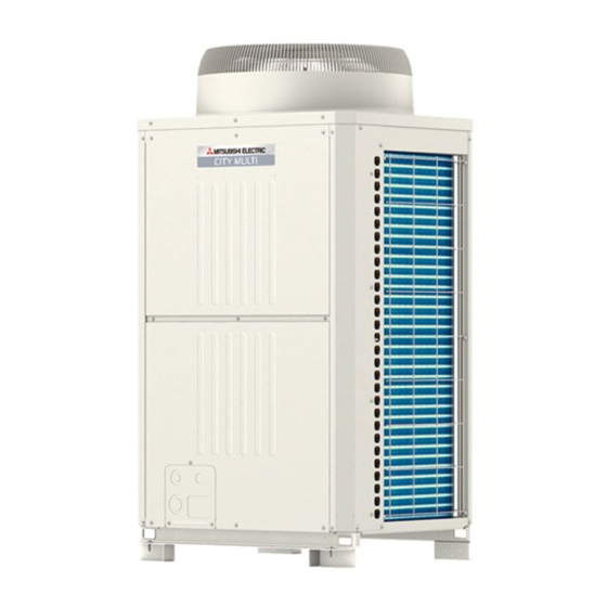
[ III Outdoor Unit Components ] III Outdoor Unit Components [1] Outdoor Unit Components and Refrigerant Circuit 1. Front view of a outdoor unit (1) PURY-RP200, RP250, RP300YJM-A Fan guard Control Box Fin guard Heat exchanger Front panel Fin guard... - Page 67 [ III Outdoor Unit Components ] 2. Refrigerant circuit (1) PURY-RP200, RP250, RP300YJM-A Solenoid valve (SV9) 2-way valve (SV6) 4-way valve (21S4a) Solenoid valve (SV2) Oil tank (top)/Refrigerant oil collector (bottom) High pressure sensor (63HS1) Check valve (CV7a) High-pressure switch...
-
Page 68: Control Box Of The Outdoor Unit
[ III Outdoor Unit Components ] [2] Control Box of the Outdoor Unit <HIGH VOLTAGE WARNING> Control box houses high-voltage parts. When opening or closing the front panel of the control box, do not let it come into contact with any of the internal components. -
Page 69: Outdoor Unit Circuit Board
[ III Outdoor Unit Components ] [3] Outdoor Unit Circuit Board 1. Outdoor unit control board CN332 CNDC Serial communication signal input Output 18VDC CN801 Bus voltage input GND (INV board) Pressure switch Output 17VDC connection (Fan board) Serial communication signal output CNAC2 driving output LED1... - Page 70 [ III Outdoor Unit Components ] 2. M-NET board CNS2 CNIT Transmission line input/output for 12VDC input CN04 centralized control system CN102 Bus voltage input 5VDC input Power supply output for centralized control system Power supply detection output Indoor/outdoor transmission line input/output Power supply ON/OFF Grounding signal input...
-
Page 71: Inv Board
[ III Outdoor Unit Components ] 3. INV board SC-P1 Rectifier diode output (P) Open: No-load operation setting CN5V RSH1 SC-P2 Short-circuited: Normal setting LED1 Overcurrent detection Bus voltage Input(P) Lit: Inverter in normal operation 5VDC output resistor Blink: Inverter error GND(Fan Board) Serial communication signal output... -
Page 72: Fan Board
[ III Outdoor Unit Components ] 4. Fan board LED3 CN18V Lit during normal Input 18VDC Serial communication signal output CPU operation GND(Control board) Serial communication signal output CN21 Serial communication signal output GND(INV board) CNVDC Input 17VDC Bus voltage input CN22 GND(INV board) Input 5VDC... -
Page 73: Noise Filter
[ III Outdoor Unit Components ] 5. Noise Filter Output Output (Rectified L2-N current) (Rectified L2-N current) Surge absorber circuit Surge absorber circuit Short circuit Short circuit Grounding F1,F2,F3,F4 Fuse 250VAC 6.3A Output Grounding CN1A Input CN1B TB21 TB22 TB23 TB24 Input Input/output(L1) -
Page 74: Bc Controller Components
[ III Outdoor Unit Components ] [4] BC Controller Components 1. CMB-P V-G1, GA1 (1) Front Liquid pipe (Indoor unit side) Gas pipe (Indoor unit side) (2) Rear view <G type> SVM1 TH11 LEV3 Gas/Liquid separator LEV1 TH16 TH12 TH15 Tube in tube heat exchanger - 65 - HWE10020... - Page 75 [ III Outdoor Unit Components ] (3) Rear view <GA type> LEV3 LEV1 TH11 SVM2 SVM1 Gas/Liquid separator Tube in tube heat exchanger TH12 TH15 - 66 - HWE10020...
- Page 76 [ III Outdoor Unit Components ] 2. CMB-P V-GB1, HB1 (1) Front Liquid pipe (Indoor unit side) Gas pipe (Indoor unit side) (2) Rear view TH12 LEV3 TH15 - 67 - HWE10020...
-
Page 77: Control Box Of The Bc Controller
[ III Outdoor Unit Components ] [5] Control Box of the BC Controller 1. CMB-P1016V-G1, GA1, HA1 Transformer Terminal block for power supply Terminal block for transmission line Relay board BC controller board - 68 - HWE10020... -
Page 78: Bc Controller Circuit Board
[ III Outdoor Unit Components ] [6] BC Controller Circuit Board 1. BC controller circuit board (BC board) - 69 - HWE10020... - Page 79 [ III Outdoor Unit Components ] 2. RELAY BOARD (RELAY 4 board) 3. RELAY BOARD (RELAY 10 board) - 70 - HWE10020...
-
Page 80: Remote Controller
IV Remote Controller [1] Functions and Specifications of MA and ME Remote Controllers ........73 [2] Group Settings and Interlock Settings via the ME Remote Controller ......74 [3] Interlock Settings via the MA Remote Controller ............. 78 [4] Using the built-in Temperature Sensor on the Remote Controller ........79 - 71 - HWE10020... - Page 81 - 72 -...
-
Page 82: Functions And Specifications Of Ma And Me Remote Controllers
[ IV Remote Controller ] IV Remote Controller [1] Functions and Specifications of MA and ME Remote Controllers There are two types of remote controllers: ME remote controller, which is connected on the indoor-outdoor transmission line, and MA remote controller, which is connected to each indoor unit. 1. -
Page 83: Group Settings And Interlock Settings Via The Me Remote Controller
[ IV Remote Controller ] [2] Group Settings and Interlock Settings via the ME Remote Controller 1. Group settings/interlock settings Make the following settings to perform a group operation of units that are connected to different outdoor units or to manually set up the indoor/outdoor unit address. - Page 84 [ IV Remote Controller ] Repeat steps in the previous page to interlock all the indoor units in a group with the LOSSNAY unit. (C) To return to the normal display When all the group settings and interlock settings are made, take the To go back to the normal display, To search for an address, follow step...
- Page 85 [ IV Remote Controller ] (A) To delete group settings (B) To delete interlock settings <Successful completion of deletion> If deletion is successfully completed, will appear in the unit type display window. If the deletion fails, will (Displayed alternately) will be displayed in the room temperature display window. appear in the unit type display - If a transmission error occurs, the selected setting will not be window.
- Page 86 [ IV Remote Controller ] [Operation Procedures] 1. Press the [ON/OFF] button on the remote controller to bring the unit to a stop. The display will appear as shown in the previous page (Normal display). 2. Press buttons [CHECK] and [ ] simultaneously for 2 seconds to go into the “Skip-Auto-Mode setting.”...
-
Page 87: Interlock Settings Via The Ma Remote Controller
[ IV Remote Controller ] [3] Interlock Settings via the MA Remote Controller 1. LOSSNAY interlock setting (Make this setting only when necessary.) * When the upper controller is connected, make the setting using the upper controller. NOTE: When using LOSSNAY units in conjunction, interlock the addresses of all indoor units within the group and address of LOSSNAY units. Perform this operation to enter the interlock setting between the LOSSNAY and the indoor units to which the remote controller is connected, or to search and delete registered information. -
Page 88: Using The Built-In Temperature Sensor On The Remote Controller
[ IV Remote Controller ] < 2. Search Procedures > To search for the LOSSNAY unit that is interlocked with a particular indoor unit, enter the address of the indoor unit into the remote controller that is connected to it. <Indoor unit address>... - Page 89 [ IV Remote Controller ] - 80 - HWE10020...
-
Page 90: Electrical Wiring Diagram
V Electrical Wiring Diagram [1] Electrical Wiring Diagram of the Outdoor Unit ..............83 [2] Electrical Wiring Diagram of the BC Controller ..............84 [3] Electrical Wiring Diagram of Transmission Booster............93 - 81 - HWE10020... - Page 91 - 82 -...
-
Page 92: Electrical Wiring Diagram Of The Outdoor Unit
[ V Electrical Wiring Diagram ] V Electrical Wiring Diagram [1] Electrical Wiring Diagram of the Outdoor Unit (1) PURY-RP200, RP250, RP300YJM-A - 83 - HWE10020... -
Page 93: Electrical Wiring Diagram Of The Bc Controller
[ V Electrical Wiring Diagram ] [2] Electrical Wiring Diagram of the BC Controller (1) CMB-P104V-G1 model - 84 - HWE10020... - Page 94 [ V Electrical Wiring Diagram ] (2) CMB-P105,106V-G1 models - 85 - HWE10020...
- Page 95 [ V Electrical Wiring Diagram ] (3) CMB-P108,1010V-G1 models - 86 - HWE10020...
- Page 96 [ V Electrical Wiring Diagram ] (4) CMB-P1013,1016V-G1 models CMB-P1013,1016V-G1 - 87 - HWE10020...
- Page 97 [ V Electrical Wiring Diagram ] (5) CMB-P108,1010V-GA1 models CMB-P108,1010V-GA1 - 88 - HWE10020...
- Page 98 [ V Electrical Wiring Diagram ] (6) CMB-P1013,1016V-GA1 models - 89 - HWE10020...
- Page 99 [ V Electrical Wiring Diagram ] (7) CMB-P104V-GB1 model - 90 - HWE10020...
- Page 100 [ V Electrical Wiring Diagram ] (8) CMB-P108V-GB1 model - 91 - HWE10020...
- Page 101 [ V Electrical Wiring Diagram ] (9) CMB-P1016V-HB1 model - 92 - HWE10020...
-
Page 102: Electrical Wiring Diagram Of Transmission Booster
[ V Electrical Wiring Diagram ] [3] Electrical Wiring Diagram of Transmission Booster Terminal block for power supply (TB1) 250V 5A Red Red Red Black White White Green/Yellow 100V/200VAC Varistor Noise filter Black White White White White Varistor Green Black Stabilized power supply Blue Black... - Page 103 [ V Electrical Wiring Diagram ] - 94 - HWE10020...
-
Page 104: Refrigerant Circuit
VI Refrigerant Circuit [1] Refrigerant Circuit Diagram ..................... 97 [2] Principal Parts and Functions ..................101 - 95 - HWE10020... - Page 105 - 96 -...
-
Page 106: Refrigerant Circuit Diagram
[ VI Refrigerant Circuit ] VI Refrigerant Circuit [1] Refrigerant Circuit Diagram 1. Outdoor unit (1) PURY-RP200, RP250, RP300 models 21S4a Solenoid valve block SV4a SV4b SV4c SV4d Oil tank CV7a 63HS1 63H1 SV1a 63LS Mineral oil collection tank CV3a... - Page 107 [ VI Refrigerant Circuit ] 2. BC controller (1) CMB-P104 - P1010V-G1 Solenoid valve block TH15 Gas/Liquid separator LEV3 TH12 TH11 LEV1 TH16 Check valve block SVM1 - 98 - HWE10020...
- Page 108 [ VI Refrigerant Circuit ] (2) CMB-P108, P1013, P1016V-GA1 (main) Solenoid valve block TH15 Gas/Liquid LEV3 separator SVM2 TH12 TH11 LEV1 TH16 Check valve block SVM1 (3) CMB-P104, P108V-GB1 (sub) Solenoid valve block TH12 TH15 LEV3 HIC-C Check valve block - 99 - HWE10020...
- Page 109 [ VI Refrigerant Circuit ] (4) CMB-P1016V-HB1 (sub) Solenoid valve block TH12 TH15 LEV3 HIC-C Check valve block - 100 - HWE10020...
-
Page 110: Principal Parts And Functions
[ VI Refrigerant Circuit ] [2] Principal Parts and Functions 1. Outdoor unit Part Symbols Notes Usage Specifications Check method name (functions) Com- Adjusts the amount of circulating 200 model pressor (Comp1) refrigerant by adjusting the operat- Low-pressure shell scroll ing frequency based on the oper- compressor ating pressure data... - Page 111 [ VI Refrigerant Circuit ] Part Symbols Notes Usage Specifications Check method name (functions) Thermis- Controls defrosting during heating Degrees Celsius Resistance (Pipe operation check = 15k temperature) = 3460 0/80 R = 15 3460 1) Detects outdoor air tempera- (Outdoor tem- ture perature)
- Page 112 [ VI Refrigerant Circuit ] Part Symbols Notes Usage Specifications Check method name (functions) Linear SLEV Controls the amount of refrigerant DC12V Same as in- expan- (Refrigerant oil oil that returns to the compressor Opening of a valve driven by a door LEV sion return)
- Page 113 [ VI Refrigerant Circuit ] 2. Indoor Unit Part Symbol Notes Usage Specification Check method Name (functions) Linear 1) Adjusts superheat at the DC12V Refer to the section expan- Opening of stepping motor "Continuity Test with a indoor heat exchanger sion valve driving valve 0-(1800) puls- Tester".
- Page 114 [ VI Refrigerant Circuit ] 3. BC controller (1) G type Symbols Part Part name Usage Specifications Check method (functions) code Pressure 1) Detects high pressure Pressure sensor (High pres- 2) LEV control 0~4.15 MPa [601psi] Vout 0.5~3.5V sure side) 1 2 3 0.071V/0.098 MPa [14psi] Pressure [MPa]...
- Page 115 [ VI Refrigerant Circuit ] (2) GA type Symbols Part Part name Usage Specifications Check method (functions) code Pressure 1) Detects high pressure Pressure sensor (High pres- 2) LEV control 0~4.15 MPa [601psi] Vout 0.5~3.5V sure side) 1 2 3 0.071V/0.098 MPa [14psi] Pressure [MPa] Con-...
- Page 116 [ VI Refrigerant Circuit ] (3) GB type Symbols Part Part name Usage Specifications Check method (functions) code Thermistor TH12 LEV control (Superheat) (Bypass = 15k outlet tem- = 3460 0/80 perature) R = 15 3460 TH15 LEV control (Superheat) 0°C[32°F] : 15kohm (Bypass in- 10°C[50°F] :9.7kohm...
- Page 117 [ VI Refrigerant Circuit ] (4) HB type Symbols Part Part name Usage Specifications Check method (functions) code Thermistor TH12 LEV control (Superheat) (Bypass = 15k outlet tem- = 3460 0/80 perature) R = 15 3460 TH15 LEV control (Superheat) 0°C[32°F] : 15kohm (Bypass in- 10°C[50°F] :9.7kohm...
-
Page 118: Control
VII Control [1] Functions and Factory Settings of the Dipswitches ............111 [2] Controlling the Outdoor Unit ..................117 [3] Controlling BC Controller ....................128 [4] Operation Flow Chart..................... 129 - 109 - HWE10020... - Page 119 - 110 -...
-
Page 120: Functions And Factory Settings Of The Dipswitches
[ VII Control ] VII Control [1] Functions and Factory Settings of the Dipswitches 1. Outdoor unit (1) Control board Function according to switch setting Switch setting timing Switch Function Unit address setting Set to 00 or 51-100 with the dial switch Before power on For self-diagnosis/oper- Refer to the LED monitor display on the outdoor... - Page 121 [ VII Control ] Function according to switch setting Switch setting timing Switch Function Test run/Refrigerant oil SW3-2, SW4-8 Dis- SW3-2, SW4-8 En- recovery operation En- Anytime after power on abled abled abled/Disabled Sends a test-run signal After power on and when Test run mode: ON/OFF Stops all ICs to all IC SW3-1 is on.
- Page 122 [ VII Control ] Function according to switch setting Switch setting timing Switch Function Model selection See the table below (Note 3) Before being energized Low-noise mode se- Capacity priority Low-noise mode Before being energized lection mode(Note 2) Model selection See the table below (Note 3) Before being energized 1) Unless otherwise specified, leave the switch to OFF where indicated by "-,"...
- Page 123 [ VII Control ] 2. Function of the switch (Indoor unit) (1) Dipswitches 1) SW1,3 Function according to switch setting Switch setting timing Switch Function Notes Set to ON (built-in sensor on the remote controller) Room temperature Built-in sensor on Indoor unit inlet on All Fresh (PEFY-VMH-F) model units detection position...
- Page 124 [ VII Control ] (2) Address switch Actual indoor unit address setting varies in different systems. Refer to the installation manual for the outdoor unit for details on how to make the address setting. Each address is set with a combination of the settings for the 10's digit and 1's digit. (Example) When setting the address to "3", set the 1's digit to 3, and the 10's digit to 0.
- Page 125 [ VII Control ] (2) ME remote controller (PAR-F27MEA) Set the address of the remote controller with the rotary switch. Rotary switch 10's digit 1's digit (left) (right) Remote controller unit Example: In case of address 108 Address setting range Setting method Main remote controller 101-150...
-
Page 126: Controlling The Outdoor Unit
[ VII Control ] [2] Controlling the Outdoor Unit -1- Outline of Control Method The outdoor units are designated as OC and OS in the order of capacity from large to small (if two or more units have the same capacity, in the order of address from small to large). When only one outdoor unit is connected, it is designated as OC. - Page 127 [ VII Control ] -4- Bypass Control Bypass solenoid valves (SV1a), which bypass the high- and low- pressure sides, perform the following functions. (1) Bypass solenoid valve (SV1a) (ON = Open) SV1a Operation When each indoor unit compressor startup ON for 4 minutes. After the restoration of thermo or 3 minutes ON for 4 minutes.
- Page 128 [ VII Control ] (5) Bypass solenoid valve (SV5b) (ON = Open) SV5c Operation While the unit is stopped Always ON Cooling mode When one or more of the following When the condition on the left is not valves is turned OFF: SV4a through SV4c.
- Page 129 [ VII Control ] -5- Compressor Frequency Control Depending on the capacity required, the frequency of the compressor is controlled to keep constant evaporation temperature (0°C [32°F] = 0.71 MPa [103 psi]) during cooling operation, and condensing temperature (49°C [120°F] = 2.88 MPa [418 psi]) during heating operation.
-
Page 130: Defrost Operation Control
[ VII Control ] -7- Defrost Operation Control (1) Starting the defrost operation The defrost cycle will start when all of the three conditions (outside temperature, cumulative compressor operation time, and pipe temperature) under <Condition 1>, <Condition 2>, or <Condition 3> are met. Condition 1 Condition 2 Condition 3... -
Page 131: Refrigerant Recovery Control
[ VII Control ] (3) Stopping the defrost operation The defrost cycle ends when 12 minutes have passed since the beginning of the cycle, or when the pipe temperature (TH3 and TH6) has been continuously detected for 2 minutes that exceeds the values in the table below Defrost operation will not stop its operation for 4 minutes once started. - Page 132 [ VII Control ] -9- Capacity Control of Outdoor Fan (1) Control method Depending on the capacity required, the rotation speed of the outdoor unit fan is controlled by the inverter to keep a constant condensing temperature of (outside temperature +10°C [50°F]) during cooling operation and a constant evaporation temper- ature of (0°C [32°F] =0.71 <Pa [103psi]) during heating operation.
- Page 133 [ VII Control ] -10- Control at Initial Start-up When started up for the first time before 12 hours have elapsed after power on, the unit goes into the initial startup mode. At the completion of the initial operation mode on the OC, they will go into the normal control mode. 1.
- Page 134 [ VII Control ] -12- Cooling/heating Circuit Control and General Function of System Equipment Operation Schematic diagram of refrigerant circuit Schematic diagram of refrigerating cycle Two-phase status Liquid 4-way valve Check valve Selector valve Low- Pressure pressure Low-pressure two-phase pipe Low-pressure Liquid Cooling...
-
Page 135: Operation Mode
[ VII Control ] -13- Operation Mode (1) Indoor unit operation mode The operation mode can be selected from the following 6 modes using the remote controller. Cooling mode Heating mode Dry mode Automatic cooling/heating mode Fan mode Stopping mode (2) Outdoor unit operation mode Cooling only mode All indoor units in operation are in cooling mode. - Page 136 [ VII Control ] -14- DEMAND Control Cooling/heating operation can be prohibited (Thermo-OFF) by an external input to the indoor units. When DIP SW4-4 is set to ON, the 4-step DEMAND control is enabled. Eight-step demand control is possible in the system with two outdoor units. Refer to Chapter II [3] 2.
-
Page 137: Controlling Bc Controller
[ VII Control ] [3] Controlling BC Controller 1. Control of SV A, SV B, and SV A, SV B, and SV C turn on or off depending on the operation mode of the branch. Mode Cooling Heating Stopped Defrost SV A Port SV B... -
Page 138: Operation Flow Chart
[ VII Control ] [4] Operation Flow Chart 1. Mode determination flowchart (1) Indoor unit (cooling, heating, dry, fan mode) Start Normal operation Error Breaker Stop turned on Operation SW turned on *Note 1 1. Protection function self-holding cancelled. 2. Indoor unit LEV fully closed. *Note 2 Remote controller Error mode... - Page 139 [ VII Control ] (2) Outdoor unit (cooling only, heating only, cooling main and heating main modes) Start Normal operation Error Breaker turned on Unit in the stopped state "HO" / "PLEASE WAIT" blinks *Note 1 on the remote controller Indoor units registered to the remote controller...
- Page 140 [ VII Control ] (3) BC controller (cooling only, heating only, cooling main and heating main modes) Start Normal operation Error Breaker turned on Unit in the stopped state Operation command 1. Determination of operation mode Protection function (Cooling only, Heating only, Mixture self-holding cancelled.
- Page 141 [ VII Control ] 2. Operations in each mode (1) Cooling operation Cooling operation Normal operation During test run mode 4-way valve OFF Unit in the stopped state Indoor unit fan *Note 1 operation Test run mode Thermostat 3-minute restart prevention 1.
- Page 142 [ VII Control ] (2) Heating operation Normal operation Heating operation Defrost operation *Note 1,2 Unit in the stopped state Defrost operation During test run mode 4-way valve ON 4-way valve OFF Test run mode 1. Indoor unit fan stop 2.
- Page 143 [ VII Control ] (3) Dry operation Dry operation Normal operation Thermostat ON 4-way valve OFF Unit in the stopped state Test run mode *Note 2 Thermostat ON Suction temperature 18 C[64 F] *Note 1 1. Indoor unit fan stop 1.
-
Page 144: Test Run Mode
VIII Test Run Mode [1] Items to be checked before a Test Run ................. 137 [2] Test Run Method ......................138 [3] Operating Characteristic and Refrigerant Amount ............139 [4] Adjusting the Refrigerant Amount .................. 139 [5] Refrigerant Amount Adjust Mode................... 142 [6] The following symptoms are normal. - Page 145 - 136 -...
-
Page 146: Items To Be Checked Before A Test Run
[ VIII Test Run Mode ] VIII Test Run Mode [1] Items to be checked before a Test Run (1) Check for refrigerant leak and loose cables and connectors. (2) Measure the insulation resistance between the power supply terminal block and the ground with a 500V megger and make sure it reads at least 1.0Mohm. -
Page 147: Test Run Method
[ VIII Test Run Mode ] [2] Test Run Method The figure shows an MA remote controller (PAR-21MAA). ON/OFF button Set Temperature buttons Down Fan Speed button TIME SUN MON TUE WED THU FRI SAT TIMER AFTER AFTER ERROR CODE FUNCTION FILTER WEEKLY... -
Page 148: Operating Characteristic And Refrigerant Amount
[ VIII Test Run Mode ] [3] Operating Characteristic and Refrigerant Amount It is important to have a clear understanding of the characteristics of refrigerant and the operating characteristics of air conditioners before attempting to adjust the refrigerant amount in a given system. 1. - Page 149 [ VIII Test Run Mode ] 3. Amount of refrigerant to be added The amount of refrigerant that is shown in the table below is factory-charged to the outdoor units. The amount necessary for extended pipe (field piping) is not included and must be added on site. Outdoor unit model RP200 RP250...
- Page 150 [ VIII Test Run Mode ] (2) Example Outdoor unit *Use a main BC controller when connecting the outdoor units of P400 model or above. BC controller Indoor Branch joint Reducer (P15 - P50 models) (Supplied with the BC Controller) Junction pipe (CMY-R160-J1) Indoor...
-
Page 151: Refrigerant Amount Adjust Mode
[ VIII Test Run Mode ] [5] Refrigerant Amount Adjust Mode 1. Procedures Follow the procedures below to adjust refrigerant charge as necessary. When the function switch (DIP SW4-3) on the outdoor unit MAIN board is turned to ON, the unit goes into the refrigerant charge adjustment mode, and the following sequence is followed. - Page 152 [ VIII Test Run Mode ] Set SW4-3 to ON to start the refrigerant charge adjustment mode. Operation mode is automatically selected. Extract 1 kg of refrigerant The refrigerant charge adjustment mode was completed from the system. within 45 minutes, and the units stopped operating. Has the operation lasted for 45 minutes? Operation has continued for 45 minutes or longer.
-
Page 153: The Following Symptoms Are Normal
[ VIII Test Run Mode ] [6] The following symptoms are normal. Remote controller Symptoms Cause display The indoor unit does not start "Cooling (heating)" The unit cannot perform a heating (cooling) operation when other indoor after starting cooling (heating) icon blinks on the units are performing a cooling (heating) operation. -
Page 154: Standard Operation Data (Reference Data)
[ VIII Test Run Mode ] [7] Standard Operation Data (Reference Data) 1. Single unit (Standard) (1) Cooling only operation Outdoor unit model Operation PURY-RP200YJM-A PURY-RP250YJM-A Model name of BC controller CMB-P104V-G1 CMB-P104V-G1 27°C/19°C 27°C/19°C Indoor Ambient [81°F/66°F] [81°F/66°F] tempera- DB/WB 35°C/- 35°C/-... - Page 155 [ VIII Test Run Mode ] Outdoor unit model Operation PURY-RP300YJM-A Model name of BC controller CMB-P104V-G1 27°C/19°C Indoor Ambient [81°F/66°F] tempera- DB/WB 35°C/- ture Outdoor [95°F/-] No. of connected units Unit Indoor unit No. of units in operation Operating Model 112/112/112 conditions...
- Page 156 [ VIII Test Run Mode ] (2) Heating only operation Outdoor unit model Operation PURY-RP200YJM-A PURY-RP250YJM-A Model name of BC controller CMB-P104V-G1 CMB-P104V-G1 20°C/- 20°C/- Indoor Ambient [68°F/-] [68°F/-] tempera- DB/WB 7°C/6°C 7°C/6°C ture Outdoor [45°F/43°F] [45°F/43°F] No. of connected units Unit Indoor unit No.
- Page 157 [ VIII Test Run Mode ] Outdoor unit model Operation PURY-RP300YJM-A Model name of BC controller CMB-P104V-G1 20°C/- Indoor Ambient [68°F/-] tempera- DB/WB 7°C/6°C ture Outdoor [45°F/43°F] No. of connected units Unit Indoor unit No. of units in operation Operating Model 112/112/112 conditions...
- Page 158 IX Troubleshooting [1] Error Code Lists ......................151 [2] Responding to Error Display on the Remote Controller..........154 [3] Investigation of Transmission Wave Shape/Noise............226 [4] Troubleshooting Principal Parts ..................229 [5] Refrigerant Leak ......................260 [6] Compressor Replacement Instructions................262 [7] Servicing the BC controller ....................
- Page 159 - 150 -...
-
Page 160: Error Code Lists
[ IX Troubleshooting ] IX Troubleshooting [1] Error Code Lists Searched unit Error Prelimi- (prelim- Error nary inary) Error code definition Notes Code error detail code code 4300 0403 Serial communication error 4305 (Note) 1102 1202 Discharge temperature fault 1301 Low pressure fault 1302 1402... - Page 161 [ IX Troubleshooting ] Searched unit Error Prelimi- (prelim- Error nary inary) Error code definition Notes Code error detail code code Indoor unit gas-side pipe temperature (TH23) OA processing unit gas- Temperature sensor 5103 1205 side pipe temperature fault (TH3) Pipe temperature at heat exchanger outlet (TH3) OA processing unit intake...
- Page 162 [ IX Troubleshooting ] Searched unit Error Prelimi- (prelim- Error nary inary) Error code definition Notes Code error detail code code 6202 Remote controller board fault (clock IC error) 6500 Indoor unit cleaning operation error 6600 Address overlaps 6601 Polarity setting error 6602 Transmission processor hardware error 6603...
-
Page 163: Responding To Error Display On The Remote Controller
[ IX Troubleshooting ] [2] Responding to Error Display on the Remote Controller 1. Error Code 0403 Serial communication error 2. Error definition and error detection method Serial communication error between the control board and the INV board on the compressor, and between the control board and the Fan board Detail code 01: Between the control board and the INV board Detail code 05: Between the control board and the Fan board... - Page 164 [ IX Troubleshooting ] 1. Error Code 1102 Discharge temperature fault 2. Error definition and error detection method 1) If the discharge temperature of 120 °C [248°F] or more is detected during the above operation (the first detection), the outdoor unit stops once, turns to anti-restart mode for 3 minutes, and restarts after 3 minutes automatically.
- Page 165 [ IX Troubleshooting ] 1. Error Code 1301 Low pressure fault 2. Error definition and error detection method When starting the compressor from Stop Mode for the first time if low pressure reads 0.098MPa [14psi] immediately before start-up, the operation immediately stops. 3.
- Page 166 [ IX Troubleshooting ] 1. Error Code 1302 High pressure fault 1 (Outdoor unit) 2. Error definition and error detection method 1) If the pressure of 3.78MPa [548psi] or higher is detected by the pressure sensor during operation (the first detection), the out- door stops once, turns to antirestart mode for 3 minutes, and restarts after 3 minutes automatically.
- Page 167 [ IX Troubleshooting ] 1. Error Code 1302 High pressure fault 2 (Outdoor unit) 2. Error definition and error detection method If the pressure of 0.098MPa [14psi] or lower is registered on the pressure sensor immediately before start-up, it will trigger an abnormal stop, and error code "1302"...
- Page 168 [ IX Troubleshooting ] 1. Error Code 2500 Drain sensor submergence (Models with a drain sensor) 2. Error definition and error detection method 1) If an immersion of the drain sensor in the water is detected while the unit is in any mode other than the Cool/Dry mode and when the drain pump goes from OFF to ON, this condition is considered preliminary water leakage.
- Page 169 [ IX Troubleshooting ] 1. Error Code 2500 Drain sensor submergence (Models with a float switch) 2. Error definition and error detection method 1) If an immersion of the float switch in the water is detected while the unit is in any mode other than the Cool/Dry mode and when the drain pump goes from OFF to ON, this condition is considered preliminary water leakage.
- Page 170 [ IX Troubleshooting ] 1. Error Code 2502 Drain pump fault (Models with a drain sensor) 2. Error definition and error detection method 1) Make the drain sensor thermistor self-heat. If the temperature rise is small, it is interpreted that the sensor is immersed in water.
- Page 171 [ IX Troubleshooting ] 1. Error Code 2502 Drain pump fault (Models with a float switch) 2. Error definition and error detection method 1) The immersion of sensor tip in water is detected by the ON/OFF signal from the float switch. ∗Submergence of the sensor When it is detected that the float switch has been ON for 15 seconds, it is interpreted that the sensor tip is immersed in water.
- Page 172 [ IX Troubleshooting ] 1. Error Code 2503 Drain sensor (Thd) fault 2. Error definition and error detection method If the open or short circuit of the thermistor has been detected for 30 seconds, this condition is considered to be a preliminary error, and the unit goes into the 3-minute restart delay mode.
- Page 173 [ IX Troubleshooting ] 1. Error Code 2600 Water leakage from humidifier 2. Error definition and error detection method 1) If the float switch for detecting water leakage is submerged in the water in the humidifier's drain pan and when the drain pump goes from OFF to ON, this condition is considered a preliminary water leakage.
- Page 174 [ IX Troubleshooting ] 1. Error Code 2601 Water supply cutoff 2. Cause, check method and remedy Cause Check method and remedy The water tank of the humidifier is empty. Check the amount of supply water. Check for the solenoid valve and for the connection. The solenoid valve for humidification is OFF.
- Page 175 [ IX Troubleshooting ] 1. Error Code 4102 Open phase 2. Error definition and error detection method An open phase of the power supply (L1 phase, N phase) was detected at power on. The L3 phase current is outside of the specified range. The open phase of the power supply may not always be detected if a power voltage from another circuit is applied.
-
Page 176: Error Code 4106
[ IX Troubleshooting ] 1. Error Code 4106 <Transmission power supply fault Error detail code FF (Outdoor unit)> 2. Error definition and error detection method Transmission power output failure 3. Cause 1) Wiring failure 2) Transmission power supply cannot output voltage because overcurrent was detected. 3) Voltage cannot be output due to transmission power supply problem. - Page 177 [ IX Troubleshooting ] 1. Error Code 4115 Power supply signal sync error 2. Error definition and error detection method The frequency cannot be determined when the power is switched on. 3. Cause, check method and remedy Cause Check method and remedy Power supply error Check the voltage of the power supply terminal block (TB1).
- Page 178 [ IX Troubleshooting ] 1. Error Code 4220 4225 Abnormal bus voltage drop (Detail code 108) 2. Error definition and error detection method If Vdc 289V or less is detected during Inverter operation. (S/W detection) 3. Cause, check method and remedy (1) Power supply environment Check whether the unit makes an instantaneous stop when the detection result is abnormal or a power failure occurs.
- Page 179 [ IX Troubleshooting ] 1. Error Code 4220 4225 Abnormal bus voltage rise (Detail code 109) 2. Error definition and error detection method If Vdc 830V is detected during inverter operation. 3. Cause, check method and remedy (1) Different voltage connection Check the power supply voltage on the power supply terminal block (TB1).
- Page 180 [ IX Troubleshooting ] 1. Error Code 4220 4225 Logic error (Detail code 111) 2. Error definition and error detection method H/W error If only the H/W error logic circuit operates, and no identifiable error is detected. 3. Cause, Check method and remedy In the case of 4220 Cause Check method and remedy...
- Page 181 [ IX Troubleshooting ] 1. Error Code 4220 4225 Low bus voltage at startup (Detail code 131) 2. Error definition and error detection method When Vdc 160 V is detected just before the inverter operation. 3. Cause, check method and remedy (1) Inverter main circuit failure Same as detail code 108 of 4220 error Refer to section -7- "Inverter"...
- Page 182 [ IX Troubleshooting ] 1. Error Code 4240 Overload protection 2. Error definition and error detection method If the output current of "(Iac) >Imax (Arms)" or "THHS > 100°C [212°F] " is continuously detected for 10 minutes or more during inverter operation. Model Imax(Arms) RP200...
- Page 183 [ IX Troubleshooting ] 1. Error Code 4250 ACCT overcurrent relay trip (Detail code 102) DCCT overcurrent relay trip (Detail code 103) Overcurrent relay trip (Detail code 106 and 107) 2. Error definition and error detection method RP200 model Overcurrent 95 Apeak or 22 Arms and above is detected by the current sensor. RP250 - RP300 models Overcurrent 95 Apeak or 35 Arms and above is detected by the current sensor.
- Page 184 [ IX Troubleshooting ] 1. Error Code 4250 4255 Overcurrent error due to short-circuited motor (Detail code 105) 2. Error definition and error detection method When a short is detected on the load side just before starting the inverter operation. 3.
- Page 185 [ IX Troubleshooting ] 1. Error Code 5101 Return air temperature sensor (TH21) fault (Indoor unit) Return air temperature sensor (TH4) fault (OA processing unit) 5102 Pipe temperature sensor (TH22) fault (Indoor unit) Pipe temperature sensor (TH2) fault (OA processing unit) 5103 Gas-side pipe temperature sensor (TH23) fault (Indoor unit) Gas-side pipe temperature sensor (TH3) fault (OA processing unit)
- Page 186 [ IX Troubleshooting ] 1. Error Code 5103 Heat exchanger outlet temperature sensor (TH3) fault (Outdoor unit) 5104 Discharge temperature sensor (TH4) fault (Outdoor unit) 5105 Accumulator inlet temperature sensor (TH5) fault (Outdoor unit) 5106 Heat exchanger inlet temperature sensor (TH6) fault (Outdoor unit) 5107 Outside temperature sensor (TH7) fault (Outdoor unit) 2.
- Page 187 [ IX Troubleshooting ] 1. Error Code 5110 Heatsink temperature sensor (THHS) fault (Detail code 01) 2. Error definition and error detection method When a short or an open of THHS is detected just before or during the inverter operation. 3.
- Page 188 [ IX Troubleshooting ] 1. Error Code 5201 High-pressure sensor fault (63HS1/63HS2) 2. Error definition and error detection method If the high pressure sensor or intermediate pressure sensor detects 0.098MPa [14psi] or less during the operation, the outdoor unit stops once, turns to anti-restart mode for 3 minutes, and restarts after 3 minutes when the detected high pressure sensor or intermediate pressure sensor is 0.098MPa [14psi] or more.
- Page 189 [ IX Troubleshooting ] 1. Error Code 5201 High-pressure sensor fault (Outdoor unit HPS/BC controller PS1) 5203 Intermediate pressure sensor fault (BC controller PS3) 2. Error definition and error detection method When a pressure sensor reading of 4.06 MPa [589 psi] or above is detected, error codes "5201" and "5203" will appear. The unit will continue its operation by using other sensors as a backup.
- Page 190 [ IX Troubleshooting ] 1. Error Code 5301 ACCT sensor fault (Detail code 115) 2. Error definition and error detection method When the formula "output current < 1.5 Arms" remains satisfied for 10 seconds while the inverter is in operation. 3.
- Page 191 [ IX Troubleshooting ] 1. Error Code 5301 ACCT sensor circuit fault (Detail code 117) 2. Error definition and error detection method When an error value is detected with the ACCT detection circuit just before the inverter starts 3. Cause, check method and remedy Cause Check method and remedy INV board failure...
- Page 192 [ IX Troubleshooting ] 1. Error Code 5301 DCCT sensor circuit fault (Detail code118) 2. Error definition and error detection method When an error value is detected with the DCCT detection circuit just before the inverter starts 3. Cause, check method and remedy Cause Check method and remedy Contact failure...
- Page 193 [ IX Troubleshooting ] 1. Error Code 5301 Open-circuited IPM/Loose ACCT connector (Detail code 119) 2. Error definition and error detection method Presence of enough current cannot be detected during the self-diagnostic operation immediately before inverter startup. 3. Cause, check method and remedy Cause Check method and remedy Inverter output wiring problem...
- Page 194 [ IX Troubleshooting ] 1. Error Code 5401 Temperature sensor fault 2. Error definition and error detection method A short-circuit or an open-circuit of the humidity sensor is detected during operation. 3. Cause, check method and remedy Cause Check method and remedy Connector contact failure (CN30) (Loose con- Check the connector for proper contact.
- Page 195 [ IX Troubleshooting ] 1. Error Code 5701 Loose float switch connector 2. Error definition and error detection method Detection of the disconnected float switch (open-phase condition) during operation 3. Cause, check method and remedy (1) CN4F disconnection or contact failure Check for disconnection of the connector (CN4F) on the indoor unit control board.
- Page 196 [ IX Troubleshooting ] 1. Error Code 6500 Indoor unit cleaning operation error 2. Error definition and error detection method This error is detected when the indoor units are operated in the mode different from the one determined by the outdoor unit during refrigerant oil recovery operation.
- Page 197 [ IX Troubleshooting ] 1. Error Code 6601 Polarity setting error 2. Error definition and error detection method The error detected when transmission processor cannot distinguish the polarities of the M-NET transmission line. 3. Cause, check method and remedy Cause Check method and remedy No voltage is applied to the M-NET transmission line Check if power is supplied to the M-NET transmission...
-
Page 198: Error Code
[ IX Troubleshooting ] 1. Error Code 6602 Transmission processor hardware error 2. Error definition and error detection method Although "0" was surely transmitted by the transmission processor, "1" is displayed on the transmission line. The address/attribute appeared on the display on the remote controller indicates the controller where an error oc- curred. - Page 199 [ IX Troubleshooting ] 1. Error Code 6603 Transmission line bus busy error 2. Error definition and error detection method Generated error when the command cannot be transmitted for 4-10 minutes in a row due to bus-busy Generated error when the command cannot be transmitted to the transmission line for 4-10 minutes in a row due to noise The address/attribute appeared on the display on the remote controller indicates the controller where an error oc- curred.
- Page 200 [ IX Troubleshooting ] 1. Error Code 6607 No ACK error 2. Error definition and error detection method The error is detected when no acknowledgement (ACK signal) is received after the transmission. (eg. When the data is trans- mitted six times in a row with 30 seconds interval, the error is detected on the transmission side.) The address/attribute appeared on the display on the remote controller indicates the controller which did not provide the response (ACK).
- Page 201 [ IX Troubleshooting ] 1. Error Code 6607 No ACK error 2. Error definition and error detection method The error is detected when no acknowledgement (ACK signal) is received after the transmission. (eg. When the data is trans- mitted six times in a row with 30 seconds interval, the error is detected on the transmission side.) The address/attribute appeared on the display on the remote controller indicates the controller which did not provide the response (ACK).
- Page 202 [ IX Troubleshooting ] 1. Error Code 6607 No ACK error 2. Error definition and error detection method The error is detected when no acknowledgement (ACK signal) is received after the transmission. (eg. When the data is trans- mitted six times in a row with 30 seconds interval, the error is detected on the transmission side.) The address/attribute appeared on the display on the remote controller indicates the controller which did not provide the response (ACK).
- Page 203 [ IX Troubleshooting ] 1. Error Code 6607 No ACK error 2. Error definition and error detection method The error is detected when no acknowledgement (ACK signal) is received after the transmission. (eg. When the data is trans- mitted six times in a row with 30 seconds interval, the error is detected on the transmission side.) The address/attribute appeared on the display on the remote controller indicates the controller which did not provide the response (ACK).
- Page 204 [ IX Troubleshooting ] 1. Error Code 6607 No ACK error 2. Error definition and error detection method The error is detected when no acknowledgement (ACK signal) is received after the transmission. (eg. When the data is trans- mitted six times in a row with 30 seconds interval, the error is detected on the transmission side.) The address/attribute appeared on the display on the remote controller indicates the controller which did not provide the response (ACK).
- Page 205 [ IX Troubleshooting ] 1. Error Code 6607 No ACK error 2. Error definition and error detection method The error is detected when no acknowledgement (ACK signal) is received after the transmission. (eg. When the data is trans- mitted six times in a row with 30 seconds interval, the error is detected on the transmission side.) The address/attribute appeared on the display on the remote controller indicates the controller which did not provide the response (ACK).
- Page 206 [ IX Troubleshooting ] 1. Error Code 6607 No ACK error 2. Error definition and error detection method The error is detected when no acknowledgement (ACK signal) is received after the transmission. (eg. When the data is trans- mitted six times in a row with 30 seconds interval, the error is detected on the transmission side.) The address/attribute appeared on the display on the remote controller indicates the controller which did not provide the response (ACK).
- Page 207 [ IX Troubleshooting ] 1. Error Code 6607 No ACK error 2. Error definition and error detection method The error is detected when no acknowledgement (ACK signal) is received after the transmission. (eg. When the data is trans- mitted six times in a row with 30 seconds interval, the error is detected on the transmission side.) The address/attribute appeared on the display on the remote controller indicates the controller which did not provide the response (ACK).
- Page 208 [ IX Troubleshooting ] 1. Error Code 6607 No ACK error 2. Error definition and error detection method The error is detected when no acknowledgement (ACK signal) is received after the transmission. (eg. When the data is trans- mitted six times in a row with 30 seconds interval, the error is detected on the transmission side.) The address/attribute appeared on the display on the remote controller indicates the controller which did not provide the response (ACK).
- Page 209 [ IX Troubleshooting ] 1. Error Code 6608 No response error 2. Error definition and error detection method When no response command is returned although acknowledgement (ACK) is received after transmission, an error is detect- When the data is transmitted 10 times in a row with 3 seconds interval, an error is detected on the transmission side. The address/attribute appeared on the display on the remote controller indicates the controller where an error oc- curred.
- Page 210 [ IX Troubleshooting ] 1. Error Code 6831 MA controller signal reception error (No signal reception) 2. Error definition and error detection method Communication between the MA remote controller and the indoor unit is not done properly. No proper data has been received for 3 minutes. 3.
- Page 211 [ IX Troubleshooting ] 1. Error Code 6832 MA remote controller signal transmission error (Synchronization error) 2. Error definition and error detection method MA remote controller and the indoor unit is not done properly. Failure to detect opening in the transmission path and unable to send signals ∗Indoor unit : 3 minutes ∗Remote controller : 6 seconds 3.
- Page 212 [ IX Troubleshooting ] 1. Error Code 6833 MA remote controller signal transmission error (Hardware error) 2. Error definition and error detection method Communication between the MA remote controller and the indoor unit is not done properly. An error occurs when the transmitted data and the received data differ for 30 times in a row. 3.
- Page 213 [ IX Troubleshooting ] 1. Error Code 6834 MA controller signal reception error (Start bit detection error) 2. Error definition and error detection method Communication between the MA remote controller and the indoor unit is not done properly. No proper data has been received for 2 minutes. 3.
- Page 214 [ IX Troubleshooting ] 1. Error Code 7100 Total capacity error 2. Error definition and error detection method The model total of indoor units in the system with one outdoor unit exceeds limitations. 3. Error source, cause, check method and remedy, Error source Cause Check method and remedy...
- Page 215 [ IX Troubleshooting ] 1. Error Code 7101 Capacity code setting error 2. Error definition and error detection method Connection of incompatible (wrong capacity code) indoor unit or outdoor unit 3. Error source, cause, check method and remedy Error source Cause Check method and remedy Outdoor unit...
- Page 216 [ IX Troubleshooting ] 1. Error Code 7102 Wrong number of connected units 2. Error definition and error detection method The number of connected indoor units is "0" or exceeds the allowable value. 3. Error source, cause, check method and remedy Error source Cause Check method and remedy...
- Page 217 [ IX Troubleshooting ] 1. Error Code 7105 Address setting error 2. Error definition and error detection method Erroneous setting of OC unit address Erroneous setting of BC controller address 3. Cause, check method and remedy Error source Cause Check method and remedy Outdoor unit Erroneous setting of OC unit address Check that the outdoor unit and BC controller...
-
Page 218: Indoor Unit
[ IX Troubleshooting ] 1. Error Code 7107 Port setting error 2. Error definition and error detection method The port with wrong number is connected to the indoor unit.The model total connected to the port is greater than the specifi- cation. - Page 219 [ IX Troubleshooting ] 1. Error Code 7110 Connection information signal transmission/reception error 2. Error definition and error detection method The given indoor unit is inoperable because it is not properly connected to the outdoor unit in the same system. 3.
- Page 220 [ IX Troubleshooting ] 1. Error Code 7113 Function setting error 2. Error source, cause, check method and remedy Error source Cause Check method and remedy Outdoor unit Wiring failure Control board connector Check the CNTYP2,4,5 connector connection. INV board connector Check the CNTYP connector connection Disconnected connector, short cir- Check the compatibility of the circuit board, and replace...
- Page 221 [ IX Troubleshooting ] 1. Error Code 7130 Incompatible unit combination 2. Error definition and error detection method The check code will appear when the indoor units for use with a different type of refrigerant or incompatible units are connect- 3.
- Page 222 [ IX Troubleshooting ] -1- Troubleshooting according to the remote controller malfunction or the external input error In the case of MA remote controller 1. Phenomena Even if the operation button on the remote controller is pressed, the display remains unlit and the unit does not start run- ning.(Power indicator does not appear on the screen.) (1) Cause...
- Page 223 [ IX Troubleshooting ] In the case of MA remote controller 2. Phenomena When the remote controller operation SW is turned on, the operation status briefly appears on the display, then it goes off, and the display lights out immediately, and the unit stops. (1) Cause 1) The power for the M-NET transmission line is not supplied from the outdoor unit.
- Page 224 [ IX Troubleshooting ] In the case of MA remote controller 3. Phenomena "HO" or "PLEASE WAIT" display on the remote controller does not disappear, and no operation is performed even if the button is pressed. ("HO" or "PLEASE WAIT" display will normally turn off 5 minutes later after the power on.) (1) Cause 1) The power for the M-NET transmission line is not supplied from the outdoor unit.
- Page 225 [ IX Troubleshooting ] Flow chart Even if the operation button on the remote controller is pressed, the indoor and the outdoor units do not start running. - 216 - HWE10020...
- Page 226 [ IX Troubleshooting ] In case of ME remote controller 1. Phenomena Even if the operation button on the remote controller is pressed, the display remains unlit and the unit does not start running. (Power indicator does not appear on the screen.) (1) Cause 1) The power for the M-NET transmission line is not supplied from the outdoor unit.
- Page 227 [ IX Troubleshooting ] In case of ME remote controller 2. Phenomena When the remote controller operation SW is turned on, a temporary operation display is indicated, and the display lights out immediately. (1) Cause 1) The power is not supplied to the indoor unit. The main power of the indoor unit (AC220V) is not on.
- Page 228 [ IX Troubleshooting ] In case of ME remote controller 3. Phenomena "HO" display on the remote controller does not disappear, and no operation is performed even if the button is pressed. (1) Cause Without using MELANS 1) Outdoor unit address is set to "00" 2) A wrong address is set.
- Page 229 [ IX Troubleshooting ] In case of ME remote controller 4. Phenomena "88" appears on the remote controller when the address is registered or confirmed. (1) Cause, check method and remedy Cause Check method and remedy An error occurs when the address is registered or con- firmed.
- Page 230 [ IX Troubleshooting ] Both for MA remote controller and ME remote controller 1. Phenomena Although cooling operation starts with the normal remote controller display, the capacity is not enough (1) Cause, check method and remedy Cause Check method and remedy Compressor frequency does not rise sufficiently.
- Page 231 [ IX Troubleshooting ] Cause Check method and remedy Long piping length Check the piping length to determine if it is contrib- The cooling capacity varies greatly depending on the uting to performance loss. pressure loss. (When the pressure loss is large, the Piping pressure loss can be estimated from the cooling capacity drops.) temperature difference between the indoor unit...
- Page 232 [ IX Troubleshooting ] 2. Phenomena Although heating operation starts with the normal remote controller display, the capacity is not enough. (1) Cause, check method and remedy Cause Check method and remedy Compressor frequency does not rise sufficiently. Check pressure difference between the detected pressure by the pressure sensor and the actual Faulty detection of pressure sensor.
- Page 233 [ IX Troubleshooting ] Cause Check method and remedy Indoor unit LEV malfunction Refer to the page of LEV troubleshooting ([4] -5- Insufficient refrigerant flows due to LEV malfunction ).(page 235) (not enough opening). Temperature reading error on the indoor unit piping Check the thermistor.
- Page 234 [ IX Troubleshooting ] 3. Phenomena Outdoor unit stops at times during operation. (1) Cause, check method and remedy Cause Check method and remedy The first stop is not considered as an error, as the Check the mode operated in the past by displaying unit turns to anti-restart mode for 3 minutes as a pre- preliminary error history on LED display with SW1.
-
Page 235: Investigation Of Transmission Wave Shape/Noise
[ IX Troubleshooting ] [3] Investigation of Transmission Wave Shape/Noise 1. M-NET transmission Control is performed by exchanging signals between the outdoor unit and the indoor unit (ME remote controller) through M- NET transmission. Noise interference on the transmission line will interrupt the normal transmission, leading to erroneous op- eration. - Page 236 [ IX Troubleshooting ] (3) Check method and remedy 1) Measures against noise Check the followings when noise exists on the wave or the errors described in (1) occur. Error code definition Remedy Check that the wiring 1. The transmission line and Isolate the transmission line from the power line (5cm [1-31/32"] or work is performed ac- the power line are not...
- Page 237 [ IX Troubleshooting ] 2. MA remote controller transmission The communication between the MA remote controller and the indoor unit is performed with current tone burst. (1) Symptoms caused by noise interference on the transmission line If noise is generated on the transmission line, and the communication between the MA remote controller and the indoor unit is interrupted for 3 minutes in a row, MA transmission error (6831) will occur.
-
Page 238: Troubleshooting Principal Parts
[ IX Troubleshooting ] [4] Troubleshooting Principal Parts -1- High-pressure sensor (63HS1, PS1, and PS3) and intermediate-pressure sensor (63HS2) 1. Compare the pressure reading on the high-pressure gauge and on the high-pressure sensor to check the high pres- sure. (Attach a pressure gauge to the check joint of the refrigerant service valve on the liquid side (BV2) to check the in- termediate pressure.) Set the digital display switch (SW1) as follows to have the high-pressure sensor reading displayed on LED1. - Page 239 [ IX Troubleshooting ] -2- Low-Pressure Sensor (63LS) 1. Compare the pressure that is detected by the low pressure sensor, and the low pressure gauge pressure to check for failure. By configuring the digital display setting switch (SW1) as shown in the figure below, the pressure as measured by the low- pressure sensor appears on the LED1 on the control board.
- Page 240 [ IX Troubleshooting ] -3- Solenoid Valve Check whether the output signal from the control board and the operation of the solenoid valve match. Setting the self-diagnosis switch (SW1) as shown in the figure below causes the ON signal of each relay to be output to the LED's. Each LED shows whether the relays for the following parts are ON or OFF.
- Page 241 [ IX Troubleshooting ] (4) SV4a - 4d 1) Depending on the conditions during Cooling-only operation, at least one of the solenoid valves among SV4a through 4d turns on. Check for proper operation on the LED and by listening for the operation sound of the solenoid valve. 2) During Heating-only operation, SV4a through 4d all turn on.
- Page 242 [ IX Troubleshooting ] Refrigerant Circuit Figure (RP200 - RP300 models) Solenoid Valves Block SV4a SV4b SV4c SV4d CV7a CV3a CV5a SV5b CV2a CV8a CV9a CV10a 63H2 63HS2 CV6a CV4a SV5c Solenoid valve block (four compartments) RP200 - RP300 models SV4d SV4c SV4b...
- Page 243 [ IX Troubleshooting ] (5) In the case of SV5b (Bypass valve) This solenoid valve closes when energized (when the relay is on). This valve turns off for five minutes after the completion of the defrost cycle, or when SV9 is on turned ON and the value of 63HS1 is greater than 3.14 MPa [455psi] during Heating-only or Heating-main operation at the minimum frequency.
- Page 244 [ IX Troubleshooting ] -5- LEV LEV operation Indoor LEV, BC controller LEV1 and 3 (Linear expansion valve) are stepping-motor-driven valves that operate by receiving the pulse signals from the indoor and outdoor unit control boards. (1) Indoor LEV and BC controller LEV The valve opening changes according to the number of pulses.
- Page 245 [ IX Troubleshooting ] 4) LEV valve closing and opening operation *When the power is turned on, the valve closing signal of 2200 pulses (Indoor LEV, BC controller LEV1 (G1 type only), and LEV3), or 3200 pulses (BC controller LEV1 (GA1 type only)), will be output from the indoor board to LEV to fix the valve position.
- Page 246 [ IX Troubleshooting ] (2) Outdoor LEV (SLEV) The valve opening changes according to the number of pulses. 1) Connections between the outdoor control board and outdoor LEV Outdoor control board DC 12V Brown Drive circuit Blue Orange Yellow White 2) Pulse signal output and valve operation Output state Output pulses change in the following orders when the...
- Page 247 [ IX Troubleshooting ] (3) Judgment methods and possible failure mode The specifications of the outdoor unit (outdoor LEV) and the indoor unit (indoor LEV) differ.Therefore, remedies for each failure may vary. Check the remedy specified for the appropriate LEV as indicated in the right column. Malfunction Judgment method Remedy...
-
Page 248: Pressure Sensor
[ IX Troubleshooting ] -6- Troubleshooting Principal Parts of BC Controller 1. Pressure sensor Troubleshooting flow chart for pressure sensor START Note 1 Check whether the pressure sensor or the connectors of P1 and P3 are connected, properly Repair the fault. Operating at the moment? Note 2 On the self-diagnosis monitor, measure... - Page 249 [ IX Troubleshooting ] 1) BC controller: Phenomena when the pressure sensor is connected wrongly (reverse connection of P1 and P3) to the board. Symptoms Cooling-only Cooling-main Heating only Heating main Non-cooling Indoor heating SC small Normal Non-cooling SC11 large SC11 large SC11 large Indoor heating SC small...
-
Page 250: Temperature Sensor
[ IX Troubleshooting ] 2. Temperature sensor Troubleshooting instructions for thermistor START Note 1 Pull out the thermistor connector in trouble from the board. Note 2 Measure the temperature of the thermistor in trouble. (actual measurement value) Note 2 Check the thermistor resistor. Compare the temperature corresponding to the resistance measured by the thermistor and the temperature measured by a commercially... - Page 251 [ IX Troubleshooting ] 1) For the connectors on the board, TH11 and TH12 are connected to CN10, and TH15 and TH16 are connected to CN11. Dis- connect the connector in trouble, and check the sensor of each number. Pull out the sensor connector from the I/O board, Do not pull the sensor by holding the lead wire. Measure the resistance with such as a tester.
- Page 252 [ IX Troubleshooting ] 3. Troubleshooting flow chart for LEV Solenoid valve (1) LEV No cooling capacity No heating capacity Note 1 Check whether the electric expansion valve and the solenoid valve connector are not disconnected or not loose. Repair the fault. Fault is found.
- Page 253 [ IX Troubleshooting ] 1) BC controller: Phenomena when LEV is connected wrongly (reverse connection of LEV1 and LEV3) to the board. Phenomena Cooling-only Cooling-main Heating only Heating main Non-cooling Non-cooling and non-heating Indoor heating SC small Non-cooling SH12 small, SC11 small SH12 small, SC11 small PHM large Indoor heating SC small...
- Page 254 [ IX Troubleshooting ] Self-diagnosis LED Measurement data Symbol SW1 setting value 1 2 3 4 5 6 7 8 9 10 LEV1 opening 1 2 3 4 5 6 7 8 9 10 LEV3 opening G, GA 1 2 3 4 5 6 7 8 9 10 BC controller bypass (Standard SH12...
- Page 255 [ IX Troubleshooting ] Troubleshooting flow chart for solenoid valve body Start Check for pins not fully inserted on the connector and check the colors of the lead wires visually. Intermediate connector Control board When LEV is fully closed : tick sound When LEV is fully open : no sound Brown Brown...
- Page 256 [ IX Troubleshooting ] (2) Solenoid valve (SVA, SVB, SVC) Faulty judgment of solenoid valve Stop the operation of the applied BC remote controller system. Stop the operation Check whether the wire to the solenoid valve is not connected wrongly, or the connector is not loose. No fault Repair the fault.
- Page 257 [ IX Troubleshooting ] Check whether the BC board output signal corresponds with the solenoid valve operation correspond. 1) SVA, SVB, SVC SVA, SVB, and SVC turn on or off according to the indoor unit operation mode. Mode Cooling Heating Stopped Defrost Port...
- Page 258 [ IX Troubleshooting ] 4. BC controller transformer BC controller control board CNTR CN03 White Normal Abnormal CNTR(1)-(3) about 58 ohm. Open-phase or shorting CN03(1)-(3) about 1.6 ohm. * Before measuring the resistance, pull out the connector. - 249 - HWE10020...
- Page 259 [ IX Troubleshooting ] -7- Inverter Replace only the compressor if only the compressor is found to be defective. Replace only the fan motor if only the fan motor is found to be defective. Replace the defective components if the inverter is found to be defective. If both the compressor and the inverter are found to be defective, replace the defective component(s) of both devices.
- Page 260 [ IX Troubleshooting ] Error display/failure condition Measure/inspection item Inverter related errors Check the details of the inverter error in the error log at [X] LED Monitor 4250, 4255, 4220, 4225, 4230, 4240,4260, 5301, 0403 Display on the Outdoor Unit Board. Take appropriate measures to the error code and the error details in ac- cordance with IX.
- Page 261 [ IX Troubleshooting ] (2) Inverter output related troubles Items to be checked Phenomena Remedy Disconnect the invert- Overcurrent error Replace the INV board. Check the er output wire from (4250 Detail code No. 101, 104, INV board er- the terminals of the 105, 106, and 107) ror detection INV board (SC-U,...
- Page 262 [ IX Troubleshooting ] Items to be checked Phenomena Remedy Disconnect the inverter Inverter-related problems are de- Connect the short-circuit con- Check whether output wire from the ter- tected. nector to CN6, and go to sec- the inverter is minals of the INV board tion [1].
- Page 263 [ IX Troubleshooting ] Items to be checked Phenomena Remedy Check the fan output wir- Connector contact failure Connect the connector. Check the fan ing. Board side (CNINV) inverter board Fan motor side failure. Check the connector CN- Cnnector contact failure Connect the connector.
- Page 264 [ IX Troubleshooting ] (3) Trouble treatment when the main power breaker is tripped Items to be checked Phenomena Remedy Check the breaker capacity. Use of a non-specified break- Replace it with a specified breaker. Perform Meg check between the Zero to several ohm, or Meg Check each part and wiring.
- Page 265 [ IX Troubleshooting ] (5) Simple checking procedure for individual components of main inverter circuit Before inspecting the inside of the control box, turn off the power, keep the unit off for at least 10 minutes, and confirm that the voltage between FT-P and FT-N on INV Board has dropped to DC20V or less. Part name Judgment method IGBT module...
- Page 266 [ IX Troubleshooting ] Judgment value (reference) Black ( + ) SC-P1 FT-N SC-L1 SC-L2 SC-L3 SC-P1 5 - 200 ohm 5 - 200 ohm 5 - 200 ohm FT-N Red (-) SC-L1 5 - 200 ohm SC-L2 5 - 200 ohm SC-L3 5 - 200 ohm Black ( + )
- Page 267 [ IX Troubleshooting ] -8- Control Circuit (1) Control power source function block Power source system (AC 380 / 415 V) Control system (DC 5 ~ 30 V) INV board Noise filter Compressor Noise filter Rectifier Smoothing capacitor Inverter AC 380/ 415V Fuse Terminal block for Inverter drive...
- Page 268 [ IX Troubleshooting ] (2) Troubleshooting transmission power circuit of outdoor unit Check the voltage at the indoor/outdoor transmission terminal block (TB3) of outdoor unit. DC 24 ~ 30 V Check whether the transmission line is disconnected, check for contact failure, and repair the problem. Check the voltage at TB3 after removing transmission line from TB3.
-
Page 269: Refrigerant Leak
[ IX Troubleshooting ] [5] Refrigerant Leak 1. Leak spot: In the case of extension pipe for indoor unit (Cooling season) 1) Mount a pressure gauge on the service check joint (CJ2) on the low-pressure side. 2) Stop all the indoor units, and close the liquid service valve (BV2) inside the outdoor unit while the compressor is being stopped. 3) Stop all the indoor units;... - Page 270 [ IX Troubleshooting ] 3. Leak spot: In the case of extension pipe for indoor unit (Heating season) (1) Run all the indoor units in heating test run mode. 1) To run the indoor unit in test run mode, turn SW3-2 from ON to OFF when SW3-1 on the outdoor control board is ON. 2) Change the setting of the remote controller for all the indoor units to the heating mode.
-
Page 271: Compressor Replacement Instructions
[ IX Troubleshooting ] [6] Compressor Replacement Instructions 1. Compressor Replacement Instructions [Compressor replacement procedures] Follow the procedures below (Steps 1 through 5) to remove the compressor components and replace the compressor. Reassemble them in the reverse order after replacing the compressor. 1. - Page 272 [ IX Troubleshooting ] Compressor covers (right and left) (The inside of the compressor cover is lined with sound insulation material.) Compressor cover (top) Belt heater 4. Remove the compressor cover (top). 5. Remove the compressor wires, compressor covers (right and left), and belt heater. Protection for the sealing material Suction piping...
- Page 273 SV4c, SV4d), Check valve (CV4a, CV6a, CV8a, CV9a, CV10a). Replace them properly according to the procedures. 1. Applicable models • PURY-RP200, 250, 300YJM-A (-BS) 2. Parts to be serviced, Set-content Following instructions are applicable to 1-4 service parts on the table below.
- Page 274 [ IX Troubleshooting ] 2) Remove the control box and the partition plate. 1) Remove the upper and lower service panels (Panel FU and FB). 3) Remove the cable that is fixed to the Frame ASSY MU (upper) and MB (lower), and remove the Frame ASSY MU and MB.
- Page 275 [ IX Troubleshooting ] (2) Check valve (CV4a, CV6a, CV8a, CV9a, CV10a) replacement procedures Remove the solenoid valve block ASSY following "(1) Solenoid valve block ASSY (SV4a, SV4b, SV4c, SV4d) replacement procedures" on the front page. Debraze I-O parts (total 6 places), and remove the Check valve ASSY. Replace the Check valve (CV4a, CV6a, CV8a, CV9a, CV10a) to be serviced while it is removed from the unit.
- Page 276 [ IX Troubleshooting ] Detailed View of Part A Brazing or debrazing pipes Check valve replacement (φ28.6 [1-1/8"]) (φ15.88 [5/8"]) When replacing CV4a: Remove the brazing When replacing CV6a: Remove the brazing (φ15.88 [5/8"]) CV6a CV4a (φ25.4 [1"]) When replacing CV8a: (φ28.6 [1-1/8"]) Remove the brazing 3 (φ15.88 [5/8"])
- Page 277 * The parts can be replaced without removing the Solenoid valve ASSY on the unit for the units that do not have built-in low pressure twinning kit (optional accessory). 2. Parts to be serviced Item Applicable models Solenoid valve PURY-RP200, 250, 300 YJM-A (-BS) (SV1a) Capillary tube ASSY PURY-RP200, 250, 300 YJM-A (-BS) (CP1) 3. Procedures Removing the Solenoid valve (SV1a) and the Capillary tube ASSY (CP1) individually is difficult when the low pressure twinning kit (optional accessory) is built in.
-
Page 278: Servicing The Bc Controller
[ IX Troubleshooting ] [7] Servicing the BC controller 1. Service panel *Special care must be taken when replacing heavy parts. Work procedure Explanatory figure 1) Remove the two lock nuts on the control box, loosen the other two, and remove the control box. 2) Remove the three fixing screws on the service panel, Ceiling panel Loosen... - Page 279 [ IX Troubleshooting ] 3. Thermistor (liquid pipe/gas pipe temperature detection) *Special care must be taken when replacing heavy parts. Work procedure Explanatory figure (1) Remove the service panel. 1) For TH11, TH12, and TH15, refer to (1)-1.2. 2) For TH16, refer to (1)-1.2.3. (GA1 type only) (2) Remove the lead wire of the piping sensor from the control board.
- Page 280 [ IX Troubleshooting ] 5. LEV Work procedure Explanatory figure (1) Remove the service panel. (See figure at right.) (2) Replace the LEV in trouble. LEV3 LEV1 Secure enough service space in the ceiling for welding operation, and conduct the work carefully.If required, dismount the unit from the ceiling, and conduct the work.
-
Page 281: Troubleshooting Using The Outdoor Unit Led Error Display
[ IX Troubleshooting ] [8] Troubleshooting Using the Outdoor Unit LED Error Display If the LED error display appear as follows while all the SW1 switches are set to OFF, check the items under the applicable item numbers below. 1. Error code appears on the LED display. Refer to IX [2] Responding to Error Display on the Remote Controller.(page 154) 2. -
Page 282: Led Monitor Display On The Outdoor Unit Board
X LED Monitor Display on the Outdoor Unit Board [1] How to Read the LED on the Service Monitor ............... 275 - 273 - HWE10020... - Page 283 - 274 -...
-
Page 284: How To Read The Led On The Service Monitor
[ X LED Monitor Display on the Outdoor Unit Board ] X LED Monitor Display on the Outdoor Unit Board [1] How to Read the LED on the Service Monitor 1. How to read the LED By setting the DIP SW 1-1 through 1-10 (Switch number 10 is represented by 0), the operating condition of the unit can be monitored on the service monitor. - Page 285 [ X LED Monitor Display on the Outdoor Unit Board ] 3. Time data storage function The outdoor unit has a simple clock function that enables the unit to calculate the current time with an internal timer by receiv- ing the time set by the system controller, such as G(B)-50A. If an error (including a preliminary error) occurs, the error history data and the error detection time are stored into the service memory.
- Page 286 [ X LED Monitor Display on the Outdoor Unit Board ] - 277 - HWE10020...
- Page 287 [ X LED Monitor Display on the Outdoor Unit Board ] - 278 - HWE10020...
- Page 288 [ X LED Monitor Display on the Outdoor Unit Board ] - 279 - HWE10020...
- Page 289 [ X LED Monitor Display on the Outdoor Unit Board ] - 280 - HWE10020...
- Page 290 [ X LED Monitor Display on the Outdoor Unit Board ] - 281 - HWE10020...
- Page 291 [ X LED Monitor Display on the Outdoor Unit Board ] - 282 - HWE10020...
- Page 292 [ X LED Monitor Display on the Outdoor Unit Board ] - 283 - HWE10020...
- Page 293 [ X LED Monitor Display on the Outdoor Unit Board ] - 284 - HWE10020...
- Page 294 [ X LED Monitor Display on the Outdoor Unit Board ] - 285 - HWE10020...
- Page 295 [ X LED Monitor Display on the Outdoor Unit Board ] - 286 - HWE10020...
- Page 296 [ X LED Monitor Display on the Outdoor Unit Board ] - 287 - HWE10020...
- Page 297 [ X LED Monitor Display on the Outdoor Unit Board ] - 288 - HWE10020...
- Page 298 [ X LED Monitor Display on the Outdoor Unit Board ] - 289 - HWE10020...
- Page 299 [ X LED Monitor Display on the Outdoor Unit Board ] - 290 - HWE10020...
- Page 300 [ X LED Monitor Display on the Outdoor Unit Board ] - 291 - HWE10020...
- Page 301 [ X LED Monitor Display on the Outdoor Unit Board ] - 292 - HWE10020...
- Page 302 [ X LED Monitor Display on the Outdoor Unit Board ] - 293 - HWE10020...
- Page 303 [ X LED Monitor Display on the Outdoor Unit Board ] - 294 - HWE10020...
- Page 304 [ X LED Monitor Display on the Outdoor Unit Board ] - 295 - HWE10020...
- Page 305 [ X LED Monitor Display on the Outdoor Unit Board ] - 296 - HWE10020...
- Page 306 [ X LED Monitor Display on the Outdoor Unit Board ] - 297 - HWE10020...
- Page 307 [ X LED Monitor Display on the Outdoor Unit Board ] - 298 - HWE10020...
- Page 308 [ X LED Monitor Display on the Outdoor Unit Board ] - 299 - HWE10020...
- Page 309 [ X LED Monitor Display on the Outdoor Unit Board ] - 300 - HWE10020...
- Page 310 [ X LED Monitor Display on the Outdoor Unit Board ] - 301 - HWE10020...
- Page 311 [ X LED Monitor Display on the Outdoor Unit Board ] - 302 - HWE10020...
- Page 312 [ X LED Monitor Display on the Outdoor Unit Board ] - 303 - HWE10020...
- Page 313 [ X LED Monitor Display on the Outdoor Unit Board ] - 304 - HWE10020...
- Page 314 [ X LED Monitor Display on the Outdoor Unit Board ] - 305 - HWE10020...
- Page 315 [ X LED Monitor Display on the Outdoor Unit Board ] - 306 - HWE10020...
- Page 316 [ X LED Monitor Display on the Outdoor Unit Board ] - 307 - HWE10020...
- Page 317 [ X LED Monitor Display on the Outdoor Unit Board ] - 308 - HWE10020...
- Page 318 [ X LED Monitor Display on the Outdoor Unit Board ] - 309 - HWE10020...
- Page 319 [ X LED Monitor Display on the Outdoor Unit Board ] - 310 - HWE10020...
- Page 320 [ X LED Monitor Display on the Outdoor Unit Board ] - 311 - HWE10020...
- Page 321 [ X LED Monitor Display on the Outdoor Unit Board ] - 312 - HWE10020...
- Page 322 [ X LED Monitor Display on the Outdoor Unit Board ] - 313 - HWE10020...
- Page 323 [ X LED Monitor Display on the Outdoor Unit Board ] - 314 - HWE10020...
- Page 324 [ X LED Monitor Display on the Outdoor Unit Board ] - 315 - HWE10020...
- Page 325 [ X LED Monitor Display on the Outdoor Unit Board ] - 316 - HWE10020...
- Page 326 [ X LED Monitor Display on the Outdoor Unit Board ] - 317 - HWE10020...
- Page 327 [ X LED Monitor Display on the Outdoor Unit Board ] - 318 - HWE10020...
- Page 328 Service Handbook Service Handbook Model PURY-RP200, RP250, RP300YJM-A http://Global.MitsubishiElectric.com Issued in Sep. 2010 HWE10020 New publication effective Sep. 2010. Printed in Japan Specifications subject to change without notice.