Table of Contents
Advertisement
Quick Links
Advertisement
Table of Contents
Troubleshooting

Related Manuals for Motorola MP6000


Summary of Contents for Motorola MP6000
- Page 1 MP6000 INTEGRATOR GUIDE...
- Page 3 MP6000 INTEGRATOR GUIDE 72E-172632-05 Revision A July 2014...
-
Page 4: Warranty
Motorola. No right to copy a licensed program in whole or in part is granted, except as permitted under copyright law. The user shall not modify, merge, or incorporate any form or portion of a licensed program with other program material, create a derivative work from a licensed program, or use a licensed program in a network without written permission from Motorola. -
Page 5: Revision History
Revision History Changes to the original guide are listed below: Change Date Description -01 Rev A 6/2013 Initial Release. -02 Rev A 6/2013 Added: - Figure 3-43, Sensormatic Coil Routing Updated: - Figure 1-2, Left Side View - Figure 3-44, Checkpoint Antenna Installation - Figure A-2 callouts - Checkpoint antenna routing color -03 Rev A... - Page 6 MP6000 INTEGRATOR GUIDE...
-
Page 7: Table Of Contents
EAS Devices ..........................1-8 Scale Devices .......................... 1-8 USB Flash Drives ........................1-8 Customer Side Scanner (CSS) ....................1-8 Features of the MP6000 ........................ 1-9 Features Summary ........................1-13 Chapter 2: HOST INTERFACES AND CABLE PINOUTS Overview ............................2-1 Interfaces, Components, and Communication ................2-2 POS Interfaces and Host Communication ................ - Page 8 USB Host Parameters ........................2-6 USB Device Type ........................2-6 Connecting an RS-232 Interface ....................2-12 MP6000 Scanner Only or MP6200/6500 Scale with Single Cable Protocol ......2-12 Price Computational Scale Interface Circuit Drawing .............. 2-13 Connect MP6000 to RS-232 Host .................... 2-14 MP6000 with a Dual Cable Scanner/Scale ................
- Page 9 Installing the MX101 on the Customer’s Left Side of the Tower Cover ......3-21 Affixing the Identification Label ..................3-23 Install the MP6000 /Scale ......................3-24 Checkstand Counter Cutouts and MP6000 Dimensions ............ 3-24 Cutout/Dimensions - MP6000 Short ................... 3-25 Cutout/Dimensions - MP6000 Short (continued) ..............3-26 Cutout/Dimensions - MP6000 Medium ................
- Page 10 Application Programming Interfaces ..................5-10 Programming Bar Codes ......................5-10 USB Staging Flash Drive ....................... 5-11 MP6000 Menu Structure for the USB Staging Flash Drive ............5-11 Manually Staging/Configuring MP6000 Devices ..............5-12 Loading Cloning Files ......................5-13 123Scan2 Staging Flash Drive Configuration ................5-14 Approved USB Flash Drives for the Flash Drive Well ..............
- Page 11 Table of Contents Status Indicator Light ....................... A-2 Troubleshooting Assistance ..................... A-3 General Error and Warning Codes ..................A-5 Scale Warning Codes ......................A-6 Appendix B: TECHNICAL SPECIFICATIONS Technical Specifications ........................ B-1 Appendix C: HOST INTERFACE CHARACTER SETS Introduction ............................ C-1 RS-232 Character Sets ........................
- Page 12 MP6000 INTEGRATOR GUIDE...
-
Page 13: About This Guide
• Chapter 2, HOST INTERFACES AND CABLE PINOUTS describes the host interfaces supported by the MP6000, how to connect the MP6000 to a host, setup, and cable pin-outs. It also includes host interface bar codes. • Chapter 3, SITE PREPARATION AND INSTALLATION describes how to install the MP6000 into a counter top. -
Page 14: Related Publications
This symbol indicates that if this information is ignored the possibility that serious WARNING personal injury may occur. Related Publications Following is a list of documents that provide additional information about configuring the MP6000: • MP6000 BAR CODE PROGRAMMING GUIDE, p/n 72E-172633-xx, provides bar codes for MP6000 configuration. - Page 15 Software type and version number (if available). Motorola responds to calls by e-mail, telephone or fax within the time limits set forth in service agreements. If your problem cannot be solved by the Motorola Solutions Global Customer Support Center, you may need to...
- Page 16 MP6000 INTEGRATOR GUIDE...
-
Page 17: Chapter 1 Product Overview And Features
CHAPTER 1 PRODUCT OVERVIEW AND FEATURES Introduction This chapter includes the following topics: • Product Overview on page 1-2 • Configurations on page 1-3 • Peripherals on page 1-8 • Features of the MP6000 on page 1-9. -
Page 18: Product Overview
Product Overview The MP6000 is a data capture solution that uses a sophisticated optical arrangement to view six sides of an object as it passes through the scanning area. Bar code data is transmitted to a Point-Of-Sale (POS) host via USB, RS-232, or RS-485. -
Page 19: Configurations
1 - 3 Configurations The MP6000 captures printed or mobile 1D or 2D bar codes. An optional customer-side scanner (CSS) can be added for bar codes displayed on mobile phones, traditional loyalty cards, or item bar codes. Hand-held scanner, integrated EAS, and scale support is also available. - Page 20 1 - 4 MP6000 INTEGRATOR GUIDE MP6000 Configurations (Continued) Table 1-1 Configuration Description MP6200-LN000M010NN Multi-plane scanner, long, with single interval scale, with Checkpoint, scale for OIML countries. MP6200-LN000M010US Multi-plane scanner, long, with single interval scale, with Checkpoint, scale for US/Puerto Rico/Guam/USVI/British VI.
- Page 21 PRODUCT OVERVIEW AND FEATURES 1 - 5 MP6000 Configurations (Continued) Table 1-1 Configuration Description MP6210-LN000M010CM Multi-plane scanner, long, single interval kg scale, with CSS, Checkpoint, Canada-Mexico scale label. MP6210-LN000M010EU Multi-plane scanner, long, with single interval scale, with Checkpoint, with CSS, scale for EU countries.
- Page 22 1 - 6 MP6000 INTEGRATOR GUIDE MP6000 Configurations (Continued) Table 1-1 Configuration Description MP6210-MP000M010US Multi-plane scanner, medium, with single interval scale, with Checkpoint, with CSS, with DL parsing, scale for US. MP6500-LN000M010CM Multi-plane scanner, long, with dual interval scale, with Checkpoint, scale for Canada/Mexico.
- Page 23 PRODUCT OVERVIEW AND FEATURES 1 - 7 MP6000 Configurations (Continued) Table 1-1 Configuration Description MP6510-MN000M010CM Multi-plane scanner, medium, with dual interval scale, with Checkpoint, with CSS, scale for Canada/Mexico. MP6510-MN000M010EU Multi-plane scanner, medium, with dual interval scale, with Checkpoint, with CSS, scale for EU.
-
Page 24: Peripherals
The MP6000 provides auxiliary data ports (USB and RS-232) to which a hand-held scanner can be connected. NOTE An auxiliary cordless scanner, such as the LI4278, LS4278, or DS6878, can be attached to the MP6000. If a presentation cradle is used with any of these scanners, a separate cradle power supply is required. -
Page 25: Features Of The Mp6000
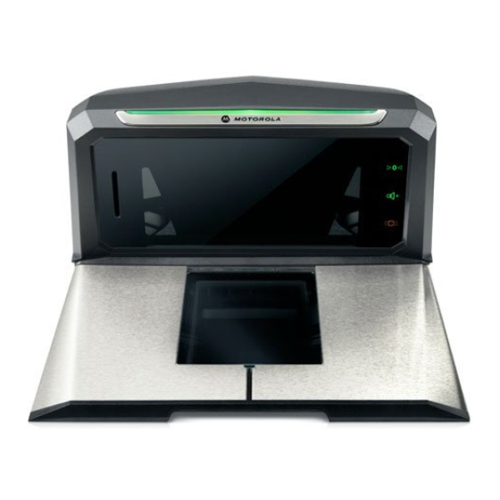
PRODUCT OVERVIEW AND FEATURES 1 - 9 Features of the MP6000 The following illustrations of the medium model show the features of the MP6000. See Table 1-2 on page 1-13 for brief descriptions of all features. See Controls and Indicators on page 5-2 for detailed descriptions of each feature. - Page 26 1 - 10 MP6000 INTEGRATOR GUIDE Tower Tower Bezel Cover EAS Cable Channel (also see Figure 3-43 on page 3-34 Sensormatic coil routing) Drainage/Ventilation Holes Scale Cable Channel Left Side View Figure 1-2 CSS Cable Drainage/Ventilation Holes Channels Strain Relief...
- Page 27 PRODUCT OVERVIEW AND FEATURES 1 - 11 Staging USB Flash Drive Cap/Port Optional Scale (scale is not available in MP6000 short models) View Under Platter Figure 1-4 Leveling Screw Access Holes (medium and short units only) NOTE The tower bezel must be...
- Page 28 1 - 12 MP6000 INTEGRATOR GUIDE Scale Displays (Some Scanner/Scale Configurations Only) - Single Head (MX201) and Dual Head Figure 1-6 (MX202; additional head added during installation)
-
Page 29: Features Summary
Calibration Switch Used in manual scale calibration (currently unavailable). CSS (Optional) Modular unit that fits into the MP6000 tower; used for customer scanning. Scale Display Single or dual display option provides the weight of items on the scale. Leveling Screws (medium and short models... - Page 30 1 - 14 MP6000 INTEGRATOR GUIDE Description of Connectors Table 1-3 Port Description RS-232 AUX 1 (J7) Table 2-3 on page 2-13 for description. 0.0 (J6) Scale Display port. RS-232 AUX 2 (J5) Table 2-3 on page 2-13 for description.
-
Page 31: Chapter 2 Host Interfaces And Cable Pinouts
CHAPTER 2 HOST INTERFACES AND CABLE PINOUTS Overview This chapter describes the host interfaces supported by the MP6000, and how to connect the MP6000 to a host. It also include host interface bar codes. See Figure 1-1 on page 1-9 for locations of the interface connectors. -
Page 32: Interfaces, Components, And Communication
Wireless auxiliary scanner support may be provided via a corded cradle as an auxiliary device. An auxiliary cordless scanner, such as the LI4278, LS4278, or DS6878, can be attached to the MP6000. If a standard cradle is used with the DS6878, a separate cradle power supply is required. -
Page 33: Programming Management Tools
Motorola scanner OPOS/JPOS APIs. For access to these programming interfaces, go to: www.motorolasolutions.com/windowssdk. NOTE If the MP6000 is powered up with no interface cable present, it reverts to “no host mode.” This is useful for demonstrations where no host is present. -
Page 34: Connecting A Usb Interface
AUX scanner connection using a Motorola USB hand-held scanner; requires a Motorola USB type A cable between the Motorola USB hand-held scanner (RJ-45), and the MP6000 AUX A-B USB port. The MP6000 is the USB host, and the Motorola scanner is the USB device which draws power from 5V cable. - Page 35 Select the USB device type by scanning the appropriate bar code (see USB Device Type on page 2-6). To modify any parameter options: Scan the appropriate bar codes in the MP6000 Bar Code Programming Guide, p/n 72E-172633-xx. Use 123Scan Use the 123Scan 2D configuration bar code.
-
Page 36: Usb Host Parameters
NOTE 1. When changing USB device types, the MP6000 automatically resets and issues the standard startup beep sequences. 2. Before selecting CDC COM Port Emulation, install the Motorola USB CDC driver on the host to ensure the scanner does not stall during power up (due to a failure to enumerate USB). If the scanner stalls, recover it by installing the CDC INF file, and reboot the MP6000. - Page 37 HOST INTERFACES AND CABLE PINOUTS 2 - 7 USB Device Type (continued) IBM Table-top USB...
- Page 38 2 - 8 MP6000 INTEGRATOR GUIDE USB Device Type (continued) IBM Hand-held USB...
- Page 39 HOST INTERFACES AND CABLE PINOUTS 2 - 9 USB Device Type (continued) IBM OPOS (IBM Hand-held USB with Full Scan Disable)
- Page 40 USB Device Type (continued) When the HID Keyboard host is selected, and the MP6000 has auxiliary scanners connected, use ADF rules to program the auxiliary scanners to add a 500 msec pause to the end of the data to prevent the interleaving of bar code data from multiple scanners.
- Page 41 HOST INTERFACES AND CABLE PINOUTS 2 - 11 USB Device Type (continued) CDC COM Port Emulation...
-
Page 42: Connecting An Rs-232 Interface
Connecting an RS-232 Interface MP6000 Scanner Only or MP6200/6500 Scale with Single Cable Protocol Use the RS-232 interface to connect the MP6000 to POS devices, host computers, or other devices with an available RS-232 port (e.g., com port). he MP6000 uses +/-6V RS-232 signal levels to accommodate long cable lengths, and increased noise NOTE immunity. -
Page 43: Price Computational Scale Interface Circuit Drawing
HOST INTERFACES AND CABLE PINOUTS 2 - 13 Auxiliary Connections Table 2-3 RS-232 Connect Device to These Ports Device Port Configuration Choices Configuration for the Devices Below Value AUX 1 AUX 2 USB2 USB3 (see parameter 1246 page 2-32 RS-232 auxiliary Sensormatic RS-232 USB auxiliary... -
Page 44: Connect Mp6000 To Rs-232 Host
Programming Guide, p/n 72E-172633-xx. MP6000 with a Dual Cable Scanner/Scale Use the RS-232 interface to connect the MP6000 to POS devices, host computers, or other devices with an available RS-232 port (e.g., com port). Then use a second RS-232 cable (p/n CBA-R51-S16ZAR, and CBA-R52-S16ZAR) to connect the MP6000 Dual Cable Scanner/Scale AUX port to a scale-only port on the POS device. -
Page 45: Rs-232 Parameters
HOST INTERFACES AND CABLE PINOUTS 2 - 15 RS-232 Parameters NOTE This guide includes limited parameter bar codes. For ALL MP6000 programming bar codes, refer to MP6000 Bar Code Programming Guide (p/n 72E-172633-xx RS-232 Host Parameters Table 2-4 Page Parameter... -
Page 46: Rs-232 Host Parameters
2 - 16 MP6000 INTEGRATOR GUIDE RS-232 Host Parameters Various RS-232 hosts use their own parameter default settings. Selecting standard, ICL, Fujitsu, Wincor-Nixdorf Mode A, Wincor-Nixdorf Mode B, OPOS/JPOS, Olivetti, Omron, Common Use Terminal Equipment (CUTE-LP/LG bar code readers), NCR, or Datalogic sets the defaults listed in... - Page 47 CR (1013) ETX ETX * CR (1013) (1003) The CUTE host disables all parameter scanning, including Set Defaults. If you inadvertently select CUTE, scan Enable Parameter Bar Code Scanning (located in the MP6000 Bar Code Programming Guide) then change the host selection.
- Page 48 2 - 18 MP6000 INTEGRATOR GUIDE RS-232 Host Parameters (continued) Selecting ICL, Fujitsu, Wincor-Nixdorf Mode A, Wincor-Nixdorf Mode B, OPOS/JPOS, Olivetti, Omron, Common Use Terminal Equipment (CUTE-LP/LG bar code readers), NCR, or Datalogic enables the transmission of code ID characters listed in...
- Page 49 HOST INTERFACES AND CABLE PINOUTS 2 - 19 Terminal Specific Code ID Characters Table 2-8 Code Type Olivetti Omron CUTE Datalogic UPC-A UPC-E None EAN-8/JAN-8 None EAN-13/JAN-13 Bookland EAN None None None Code 39 M <len> C <len> Code 39 Full ASCII None None None...
-
Page 50: Rs-232 Host Types
Selecting another RS-232 host type bar code changes these settings. 2. The CUTE host disables all parameter scanning, including Set Defaults. If you inadvertently select CUTE, scan Enable Parameter Bar Code Scanning (located in the MP6000 Bar Code Programming Guide) then change the host selection. - Page 51 HOST INTERFACES AND CABLE PINOUTS 2 - 21 RS-232 Host Types (continued) Standard RS-232...
- Page 52 2 - 22 MP6000 INTEGRATOR GUIDE RS-232 Host Types (continued) ICL RS-232...
- Page 53 HOST INTERFACES AND CABLE PINOUTS 2 - 23 RS-232 Host Types (continued) Wincor-Nixdorf RS-232 Mode A...
- Page 54 2 - 24 MP6000 INTEGRATOR GUIDE RS-232 Host Types (continued) Wincor-Nixdorf RS-232 Mode B...
- Page 55 HOST INTERFACES AND CABLE PINOUTS 2 - 25 RS-232 Host Types (continued) Olivetti ORS4500...
- Page 56 2 - 26 MP6000 INTEGRATOR GUIDE RS-232 Host Types (continued) Omron...
- Page 57 HOST INTERFACES AND CABLE PINOUTS 2 - 27 RS-232 Host Types (continued) OPOS/JPOS...
- Page 58 2 - 28 MP6000 INTEGRATOR GUIDE RS-232 Host Types (continued) Fujitsu RS-232...
- Page 59 HOST INTERFACES AND CABLE PINOUTS 2 - 29 RS-232 Host Types (continued) CUTE...
-
Page 60: Rs-232 Host -Ncr Variant
Scan the bar code below to enable the NCR variant of the RS-232 host. IMPORTANT There are several parameter options available with the NCR variant for RS-232. Refer to MP6000 Bar Code Programming Guide, p/n 72E-172633-xx to manage the following NCR related parameters: •... -
Page 61: Rs-232 Host -Datalogic Variant
HOST INTERFACES AND CABLE PINOUTS 2 - 31 RS-232 Host Types (continued) RS-232 Host -Datalogic Variant Scan the bar code below to enable the Datalogic variant of the RS-232 host. Datalogic Variant... -
Page 62: Rs-232 Device Port Configuration
RS-232 Device Port Configuration Parameter # 1246 This option allows the user to select which devices to attach to the MP6000, and to which port they are attached. Scan the appropriate bar codes that follow to select the proper configuration. The available configurations are: •... - Page 63 HOST INTERFACES AND CABLE PINOUTS 2 - 33 RS-232 Device Port Configuration (continued) *AUX 1 Sensormatic and AUX 2 RS-232 Scanner (00h)
- Page 64 2 - 34 MP6000 INTEGRATOR GUIDE RS-232 Device Port Configuration (continued) AUX 1 Dual Cable Scale and AUX 2 RS-232 Scanner (01h)
- Page 65 HOST INTERFACES AND CABLE PINOUTS 2 - 35 RS-232 Device Port Configuration (continued) AUX 1 Sensormatic and AUX 2 Dual Cable Scale (02h)
- Page 66 2 - 36 MP6000 INTEGRATOR GUIDE RS-232 Device Port Configuration (continued) AUX 1 Third Party Scale, AUX 2 Sensormatic (04h)
-
Page 67: Third Party Scale Parameters
HOST INTERFACES AND CABLE PINOUTS 2 - 37 Third Party Scale Parameters Third Party Scale Parameter # 1294 Enable or disable Third Party Scale functionality. When disabled Third Party Scale LED Pin (parameter # 1295) and Third Party Scale Zero Pin (parameter # 1296) are ignored/overridden. (Also see Price Computational Scale Interface Circuit Drawing on page 2-13.) -
Page 68: Third Party Scale
2 - 38 MP6000 INTEGRATOR GUIDE Third Party Scale (continued) * Disable Third Party Scale... -
Page 69: Third Party Scale Led Pin
HOST INTERFACES AND CABLE PINOUTS 2 - 39 Third Party Scale LED Pin Parameter # 1295 This parameter defines the polarity of the LED/Tare input pin that illuminates the scale LED. This parameter has no effect if Third Party Scale (parameter # 1294) is disabled. Options: •... - Page 70 2 - 40 MP6000 INTEGRATOR GUIDE Third Party Scale LED Pin (continued) *Active High...
-
Page 71: Third Party Scale Zero Pin
HOST INTERFACES AND CABLE PINOUTS 2 - 41 Third Party Scale Zero Pin Parameter # 1296 This parameter defines the polarity of the zero output pin when the Scale Zero button is pressed. This parameter has no effect if Third Party Scale (parameter # 1294) is disabled. Options: •... - Page 72 2 - 42 MP6000 INTEGRATOR GUIDE Third Party Scale Zero Pin (continued) *Active High...
-
Page 73: Connecting An Ibm Rs-485 Interface
To set up the MP6000: Attach the modular connector of the IBM RS-485 interface cable to the POS interface port on the MP6000. Connect the other end of the IBM RS-485 interface cable to the appropriate port on the host (typically Port 9). -
Page 74: Ibm Rs-485 Host Parameters
2. The port numbers in Table 2-9 are no longer physical ports on the IBM POS. NOTE This guide includes limited parameter bar codes. For ALL MP6000 programming bar codes, refer to MP6000 Bar Code Programming Guide (p/n 72E-172633-xx IBM RS-485 Port Parameters... - Page 75 HOST INTERFACES AND CABLE PINOUTS 2 - 45 IBM Port Addresses None Selected...
-
Page 76: Hand-Held Scanner Emulation (Port 9B)
2 - 46 MP6000 INTEGRATOR GUIDE IBM Port Addresses (continued) Hand-held Scanner Emulation (Port 9B) -
Page 77: Non-Ibm Scanner Emulation (Port 5B)
HOST INTERFACES AND CABLE PINOUTS 2 - 47 IBM Port Addresses (continued) Non-IBM Scanner Emulation (Port 5B) - Page 78 2 - 48 MP6000 INTEGRATOR GUIDE IBM Port Addresses (continued) Tabletop Scanner Emulation (Port 17)
-
Page 79: Ibm Scale Port Addresses
HOST INTERFACES AND CABLE PINOUTS 2 - 49 IBM Scale Port Addresses The scale port address must be configured for the scale to operate on the IBM RS-485 bus. The default is None Selected. None Selected... -
Page 80: Port 6A
2 - 50 MP6000 INTEGRATOR GUIDE IBM Scale Port Addresses (continued) Port 6A... -
Page 81: Port 6B
HOST INTERFACES AND CABLE PINOUTS 2 - 51 IBM Scale Port Addresses (continued) Port 6B... -
Page 82: Port 6E
2 - 52 MP6000 INTEGRATOR GUIDE IBM Scale Port Addresses (continued) Port 6E... -
Page 83: Connector Pins
HOST INTERFACES AND CABLE PINOUTS 2 - 53 Connector Pins RS-232 AUX 1 RJ-45 Table 2-10 Pin # Signal/Name Direction Description No Connection RS-232 scanner 5VDC Supply Signal Ground Serial TXD (±5.4V) Serial RXD (±5.4V) Serial RTS (±5.4V) Serial CTS (±5.4V) Scale LED Indicates price computational scale has returned to zero - reflected in UI Scale Status LED (if enabled). -
Page 84: Aux 2
2 - 54 MP6000 INTEGRATOR GUIDE RS-232 AUX 2 RJ-45 Table 2-12 Pin # Signal/Name Direction Description No connection RS-232 scanner 5V supply Signal ground Serial TXD (±5.4V) Serial RXD (±5.4V) Serial RTS (±5.4V) Serial CTS (±5.4V) No connection No connection Output for auxiliary device. -
Page 85: Pos
(Power From Terminal) * Terminal systems vary in power capabilities. Ensure your system power supply is capable of the MP6000 configuration power requirements. For terminals unable to support P.O.T., a 12V DC barrel jack is available for external power. 12V DC 12V DC Jack, 2.5mm... - Page 86 2 - 56 MP6000 INTEGRATOR GUIDE...
-
Page 87: Chapter 3 Site Preparation And Installation
CHAPTER 3 SITE PREPARATION AND INSTALLATION Overview The MP6000 was designed to drop into an existing bioptic checkstand cutout with no modifications. The unit is available in three industry standard sizes (for more detailed information, see Appendix B, TECHNICAL SPECIFICATIONS): •... -
Page 88: Site Preparation
Checkstand ventilation may be required to ensure the MP6000 temperature limits are not exceeded. If forced air ventilation is used, it must not pass through the MP6000 as this can produce an unstable weighing environment. The ambient air temperature inside the checkstand, adjacent to the device, must not exceed 104°F (40°C). -
Page 89: Electrical Power Considerations
SITE PREPARATION AND INSTALLATION 3 - 3 Electrical Power Considerations The MP6000 may be powered from two different sources: • POS Equipment • IBM register with powered Port 9B interface (using p/n CBA-M51-S16PAR accessory cable) • NCR POS with powered RS-232 interface (using p/n CBA-R55-S16PAR accessory cable) •... -
Page 90: Checkstand Preparation
Checkstand Preparation If the MP6000 is not replacing an old bioptic device, and you are installing for the first time into a new checkstand, verify that the area allows for proper cabling, and an AC/DC power supply. Mounting may require installation of support(s), leveling screws, and peripheral devices. -
Page 91: Counter Cutout
SITE PREPARATION AND INSTALLATION 3 - 5 Counter Cutout There are three different MP6000 models: long, medium, and short. Prior to cutting the counter opening, ensure you have the dimensions for the scanner/scale being installed (see Figure 3-29, Figure 3-33, and Figure 3-37). -
Page 92: Installing Components
3 - 6 MP6000 INTEGRATOR GUIDE Installing Components The MP6000 can be installed with or without the following options: • Scale and Scale Display (depending on Weights and Measure regulatory jurisdictions, a Scale Display may be required for units with a scale) •... -
Page 93: Remove Existing Bioptic Scanner And Accessories
Remove it from the checkstand. Remove its cables. Remove the Scale Display. Remove the existing bioptic scanner. Unpacking MP6000 Equipment To unpack equipment: Remove all components from their packaging, and check that all parts are present. Each box includes the material listed in Table 3-1. -
Page 94: Pre-Installation Notes
Do not use a sharp object to remove the protector. Doing so can damage the platter. Keep the packing (it is the approved shipping container, and should be used if the MP6000 needs to be returned for servicing), or dispose of the packing in an environmentally sensitive manner. -
Page 95: Assemble The Dual Head Scale Display
SITE PREPARATION AND INSTALLATION 3 - 9 Assemble the Dual Head Scale Display NOTE This only applies when adding a second display head to a single display. Required Tools • Phillips head screw driver. To convert a single display to a double display: The second Scale Display head ships with a cable (already fitted), pole grip, two M3 x 12 self tapping Phillips screws, and a set of four display overlays. - Page 96 3 - 10 MP6000 INTEGRATOR GUIDE Remove the circular cap from the existing display and either discard, or keep it as a spare part. Removing Circular Cap Figure 3-7 Connect the cable from the new display to the RJ-11 port marked “To Slave” on the PCB in the existing (single head) display.
- Page 97 SITE PREPARATION AND INSTALLATION 3 - 11 Secure in place using the pole grip and two M3 x 12 self tapping screws supplied. These are Phillips screw heads. Secure in Place Figure 3-10 Replace the case back of the existing (original single-head) display using the four M3 x 18 self tapping screws (removed earlier).
-
Page 98: Install The Scale Display
3 - 12 MP6000 INTEGRATOR GUIDE Install the Scale Display When installing the optional Scale Display, consider both the cashier and customer’s viewing angle. Both must see the weight value displayed. 2.3 in 58.0 mm 3.0 in 75.0 mm 3.1in 77.5 mm... - Page 99 SITE PREPARATION AND INSTALLATION 3 - 13 2.8 in 70.0 mm 3.0 in 75.0 mm 3.1 in 77.5 mm 6.1 in 155.0 mm 2.3 in 2.3 in 57.5 mm Dual Scale Display - Dimensions; Display Rotates Independently (Approximately 290 Figure 3-12...
-
Page 100: Getting Started
Identify the location to install the Scale Display. Identify the location to place the Scale Display based on counter design and viewing angle. Place the unit where it cannot impede access to scanned items being swept over the MP6000, payment terminals, printer validation and paper roll slots, access to replace consumables (rolls) etc. -
Page 101: Installing
Weights and Measures label. Depending on the unit, and the country location, labels vary. You MUST match the label to the type of MP6000 scale you are installing. (Labels, and instructions for their use, are packaged with the Scale Display.) •... -
Page 102: Install The Customer Side Scanner (Mx101)
Install the Customer Side Scanner (MX101) The MX101 is an optional modular unit that fits into a modified MP6000 tower and is used for customer scanning. The unit can be installed on either the left or right side of the MP6000. -
Page 103: Installing The Mx101 On The Customer's Right Side (Default) Of The Tower Cover
To install the MX101 on the customer’s right side (default) of the MP6000: Remove the MP6000 tower bezel by squeezing inward on both the left and right sides of the lower part of the tower bezel, pushing its side snaps to disengage. Slide the tower bezel up and lift out. - Page 104 3 - 18 MP6000 INTEGRATOR GUIDE Remove the scan window cover from the CSS tower by squeezing the snaps shown below. The snaps are squeezed from inside the tower cover. Snaps Removing the Scan Window Cover Figure 3-17 Insert the scan module into place facing out of the opening of the CSS tower cover. Ensure the grommets on the scan module align with the sockets in the tower cover, and push into place.
- Page 105 NOTE Ensure you hear and feel three distinct snaps: one for each snap mechanism (lower, front, rear), to ensure a snug fit in the rear tower. Connect the USB cable to the top USB auxiliary port (recommended) on the MP6000. Route the cable into the side cable slots as shown.
- Page 106 NOTE The path through the cable slots is not intuitive. Send the cable towards the left of the tower (as shown) even though the CSS module is on the right. (Take up all the slack outside the MP6000 chassis so the CSS cable cannot be pinched by the checkstand.)
-
Page 107: Installing The Mx101 On The Customer's Left Side Of The Tower Cover
Slide the CSS tower cover back into place. Ensure the cable service loop folds up into the blank space in the CSS tower cover, on the opposite side from the scan module. Snaps should click together. When the tower cover is replaced, the module locks into the grommet compression ribs on the MP6000 inner tower. Replacing the Tower Cover Figure 3-23 Replace MP6000 tower bezel. - Page 108 Snap the scan window cover into place on the tower, over the scan window. (See page 3-19 for diagrams.) Connect the USB cable to the top USB port (recommended) on the MP6000 and route the cable through the side cable slots shown in step page...
-
Page 109: Affixing The Identification Label
NOTE The path through the cable slots is not intuitive. Send the cable towards the right of the tower (as shown) even though the CSS module is on the left. (Take up all the slack outside the MP6000 chassis so the CSS cable cannot be pinched by the checkstand.) -
Page 110: Install The Mp6000 /Scale
3-36). The MP6000 is 4 in. deep. If replacing a pre-existing 5 in. deep short or medium scanner, you must use the 1 in. longer leveling screw kit (p/n MX302-SR00004ZZWR). This will bring the platter up to the countertop level. -
Page 111: Cutout/Dimensions - Mp6000 Short
44.6 mm +/- 6.6 mm 44.6 mm +/- 6.6 mm Support Rails MP6000 - Short Unit (No Scale) Front View Dimensions Figure 3-30 IMPORTANT Use the support rails as shown, and not a shelf. If liquid spills it pools on a shelf. -
Page 112: Cutout/Dimensions - Mp6000 Short (Continued)
3 - 26 MP6000 INTEGRATOR GUIDE Cutout/Dimensions - MP6000 Short (continued) 11.50 in. 292.2 mm 13.90 in. 353.1 mm MP6000 - Short Unit (No Scale) Top View Dimensions Figure 3-31 14.03 in. +/- 0.06 in. 356.2 mm +/- 1.5 mm (Counter Opening) 5.1 in. -
Page 113: Cutout/Dimensions - Mp6000 Medium
1.75 in. +/- 0.25 in. 44.5 mm +/- 6.6 mm 44.5 mm +/- 6.6 mm MP6000 - Medium Unit Front View Dimensions Figure 3-34 IMPORTANT Use the support rails as shown, and not a shelf. If liquid spills it pools on a shelf. - Page 114 5.1 in. 128.5 mm 4.00 in. 101.6 mm Optional leveling screw kit MX301-SR00004ZZWR or MX302-SR00004ZZWR MP6000 - Medium Unit Side View Dimensions Figure 3-35 11.50 in. 292.2 mm 15.66 in. 397.8 mm MP6000 - Medium Unit Top View Dimensions Figure 3-36...
-
Page 115: Cutout/Dimensions - Mp6000 Long
101.6 mm Max 18.63 in. 473.1 mm MP6000 - Long Unit Side View Dimensions Figure 3-38 NOTE The countertop, after routing, must have sufficient strength to support the scanner and the loads placed on top of it. If the countertop is not strong enough, add strengthening supports underneath the countertop... - Page 116 Cutout/Dimensions - MP6000 Long (continued) 11.50 in. 292.2 mm 20.0 in. 506.9 mm MP6000 - Long Unit Top View Dimensions Figure 3-39 To install the MP6000: Ensure the following items were completed: Existing scanner and accessories were removed, if applicable. See...
- Page 117 SITE PREPARATION AND INSTALLATION 3 - 31 To grasp the MP6000 to lower it into the checkstand, use the support handle on the back of the tower cover together with the front part of the scale, or the handle in the front flange area (if installing the long model).
- Page 118 3 - 32 MP6000 INTEGRATOR GUIDE Medium MP6000 and short (shelf mount) MP6000: If the platter is not flush, or the MP6000 rocks, adjust the optional leveling screws to place the device at the correct height. This can be done from the top of the MP6000, with the tower bezel removed and the tower cover slightly pushed back.
-
Page 119: Install Sensormatic Coils
Disconnect power to the MP6000. Remove the MP6000 tower bezel by squeezing inward on both the left and right sides of the lower part of the tower bezel, pushing its side snaps to disengage. Slide the tower bezel up and lift out. (See... - Page 120 Secure each coil with two screws. Route the coil wires through the key hole on the side of the MP6000 for connection to the controller box. Leave the wires free, under the MP6000, for a Sensormatic representative to make the connection to the controller.
-
Page 121: Install Checkpoint Antenna
SITE PREPARATION AND INSTALLATION 3 - 35 Install Checkpoint Antenna The Checkpoint EAS single axis wire loop antenna should be looped around the middle housing of the MP6000, under the platter, and should route through the pinch points as shown in Figure 3-44. There is no vertical antenna. -
Page 122: Trim Kit Installation (If Required)
12 in. wide NCR scanner/scale. The trim can be mounted on either side of the MP6000. It should be installed in the downstream side of the conveying goods. The trim adds 0.5 in. (1.2 cm) to the width of the MP6000. -
Page 123: Mp6000 Mounting Frame (If Required)
SITE PREPARATION AND INSTALLATION 3 - 37 MP6000 Mounting Frame (If Required) Installing the Mounting Frame Figure 3-47... - Page 124 3 - 38 MP6000 INTEGRATOR GUIDE...
-
Page 125: Chapter 4 Scale Calibration (Models With A Scale Only)
CHAPTER 4 SCALE CALIBRATION (MODELS WITH A SCALE ONLY) Overview This chapter describes how to calibrate the scale in the MP6000, and how to program its features. The parameter bar codes included in this chapter are listed in Table 4-1. -
Page 126: Scale Calibration Procedure (Scanner/Scale Configurations Only)
(model # ending in -08). IMPORTANT The MP6000 platter can be removed to see the model number of the scale. The model number is printed on a label affixed to the right side of the bottom bar of the scale’s U frame. The last two digits in the model number define the scale’s configuration (see... -
Page 127: Step 1 - Electronic Entry Into Calibration Mode
If the weight units change from lb to kg, this setting is enabled after a cold power start of the MP6000. A scale reset (e.g., via the Scale Reset STISCLRST bar code) WILL NOT enable this setting. Likewise, if... -
Page 128: Legal Scale Dampening Filter
4 - 4 MP6000 INTEGRATOR GUIDE Legal Scale Dampening Filter Set the scale sensitivity to vibration by scanning the appropriate bar code (see page 4-17). To program this parameter, the scale must be in Calibration Mode. Bar code command values are as follows: •... - Page 129 SCALE CALIBRATION (MODELS WITH A SCALE ONLY) 4 - 5 Depending on the units of measure programmed, place 25 lb or 11 kg on the scale. Ideally these weights should be grouped in the center of the scale (Figure 4-1). Center of Scale (A) Center of Scale Location, and (B) Center of Scale Location with Platter Installed...
- Page 130 4 - 6 MP6000 INTEGRATOR GUIDE Place 11 kg weights on the scanner as shown in Figure 4-3; two 5 kg weights centered on the center of the scale, and one 1 kg weight on top between the two 5 kg weights.
-
Page 131: Step 5 - Calibration Success Or Failure
After the Scale Display starts blinking between CAL P and CAL S, remove the weights from the scale. Touch the Scale Zero button for the scale to reset. The MP6000 scanner/scale emits three short beeps to indicate that the calibration was successful and all parameters are saved. -
Page 132: Verification Test
(fails). • A user scans Scale Reset (refer to the MP6000 Bar Code Programming Guide, p/n 72E-172633-xx). When Scale Reset is scanned, a test runs, showing a series of characters on the optional Scale Display. When the test completes, the scale returns to its prior state before entering a scale Calibration Mode. - Page 133 SCALE CALIBRATION (MODELS WITH A SCALE ONLY) 4 - 9 Verification Tests for US (lb) Scales (Continued) Table 4-4 All Tolerances All Tolerances Indication = Applied Are +/- Are +/- Verification Test for US Load Within Scale Applied Load lb Applicable Tolerances Acceptance...
- Page 134 4 - 10 MP6000 INTEGRATOR GUIDE Verification Tests for Metric Scale (Continued) Table 4-5 All Tolerances All Tolerances Indication = Applied Verification Test for Are +/- Are +/- Load Within Metric Scale Applied Applicable Load kg Acceptance Acceptance Tolerances Single Int Dual Int 5.000...
-
Page 135: Audit Tallies
SCALE CALIBRATION (MODELS WITH A SCALE ONLY) 4 - 11 While performing a shift test, the indication of each position is within the applicable tolerance and the range of results obtained should not exceed twice the applicable tolerance. IMPORTANT After verification, record/report audit trail information to the local Weights and Measure authority where required by law. -
Page 136: Scale Configuration Parameters
Legal Scale Units Parameter # 995 Scan a weight unit below to set the legal weight units for the MP6000. Scan Kilograms for metric units; scan Pounds for the US units. IMPORTANT The scale must be in a calibration mode to change this parameter. - Page 137 SCALE CALIBRATION (MODELS WITH A SCALE ONLY) 4 - 13 Legal Scale Units (continued) Pounds...
-
Page 138: Scale Display Configuration
4 - 14 MP6000 INTEGRATOR GUIDE Scale Display Configuration Parameter # 986 Scan Enable Scale Display Configuration below to enable the Scale Display port. The Scale Display port is disabled by default. Enable Scale Display Configuration... - Page 139 SCALE CALIBRATION (MODELS WITH A SCALE ONLY) 4 - 15 Scale Display Configuration (continued) Disable Scale Display Configuration...
-
Page 140: Legal Scale Dampening Filter Setting
4 - 16 MP6000 INTEGRATOR GUIDE Legal Scale Dampening Filter Setting Parameter # 996 Scan a bar code below to set the vibration sensitivity of the scale. The lower the number value, the more sensitive the scale is to vibration. The scale must be in a Calibration Mode to program this parameter. - Page 141 SCALE CALIBRATION (MODELS WITH A SCALE ONLY) 4 - 17 Parameter # 996 (continued) Low Vibration Sensitivity...
- Page 142 4 - 18 MP6000 INTEGRATOR GUIDE Parameter # 996 (continued) Very Low Vibration Sensitivity...
- Page 143 SCALE CALIBRATION (MODELS WITH A SCALE ONLY) 4 - 19 Parameter # 996 (continued) Ultra Low Vibration Sensitivity...
-
Page 144: User Interface Displays And Signals
4 - 20 MP6000 INTEGRATOR GUIDE User Interface Displays and Signals LEDs, and Beeper Sequences Table 4-6 Scale 7-segment Beeper Zero Scale State Optional Scale Display Diagnostic Display (System) Sequence Button (LED) Scale disabled No change No change None Blank... - Page 145 SCALE CALIBRATION (MODELS WITH A SCALE ONLY) 4 - 21 LEDs, and Beeper Sequences (Continued) Table 4-6 Scale 7-segment Beeper Zero Scale State Optional Scale Display Diagnostic Display (System) Sequence Button (LED) Successfully Step 2 - Program No change Five long beep Step 3 - Calibration at NO entering scale Legal Parameters...
- Page 146 4 - 22 MP6000 INTEGRATOR GUIDE LEDs, and Beeper Sequences (Continued) Table 4-6 Scale 7-segment Beeper Zero Scale State Optional Scale Display Diagnostic Display (System) Sequence Button (LED) Successfully Calibration procedure No change Three short Solid green Scale is reset either by...
-
Page 147: Chapter 5 Operating The Scanner
CHAPTER 5 OPERATING THE SCANNER Overview This chapter describes how to operate the MP6000, including information about indicators (LEDs, beeper, etc,), beeper/speaker, user buttons, weighing items, and the 7-segment character (diagnostic) display. -
Page 148: Controls And Indicators
5 - 2 MP6000 INTEGRATOR GUIDE Controls and Indicators Table 5-1 on page 5-20 for all beeper and LED indications. LED Array Bar LED Array Bar LED Array Bar Figure 5-1 The LED array is located on the top of the device... -
Page 149: Diagnostic Led/7-Segment Display
OPERATING THE SCANNER 5 - 3 Diagnostic LED/7-segment Display 7-segment Display 7-segment Display Figure 5-2 Figure 5-2 shows the internal 7-segment display which provides error and warning codes, scale legal parameters and lead through help during scale calibration. It is visible inside the scanner’s vertical window. The 7-segment display is a one character display. -
Page 150: Front Panel Buttons
This audible indication informs the user that the scanner is working, and not malfunctioning. NOTE If the decode tone is set to off, the Volume/Tone button on the MP6000 is not operational. To enable the Volume/Tone button, set a tone option other than Off tone. Refer to the beeper and tone settings in the MP6000 Bar Code Programming Guide (p/n 72E-172633-xx). -
Page 151: Sensormatic Manual Activation And Sensormatic Status Button
Soft Reset Buttons Soft Reset Buttons Figure 5-6 A soft reset of the MP6000 can be initiated by pressing the Scale Zero and EAS buttons simultaneously for 10 seconds. A two second beep sounds, then a system reset is performed. -
Page 152: Mp6000 Related Hardware
Customer Side Scanner (CSS) - Optional The CSS is a modular unit which is either embedded in the MP6000 tower, or added at any time to fit on the left or right side of the MP6000. The CSS snaps on to the MP6000 and requires no tools to install or remove. -
Page 153: Platter
Installing/Removing the Long Non-Scale and Medium Scale Platters These platters have a lip at the cashier end which can be gripped for lifting. To install the platter(s) drop the tower-end of the platter into the MP6000 first, and then lower the cashier end down using the lip. -
Page 154: Installing/Removing The Long Scale Platter
Installing/Removing the Long Scale Platter The long scale platter installs down into, and hooks onto the scale assembly. To install the platter on a long MP6000 with a scale: Line up the hooks on the platter with the notches in top scale frame. -
Page 155: Scan Windows
Figure 5-9 Scan Windows The MP6000 provides six sided scanning, including reading top down and cashier side bar codes. 2D scanning (PDF, Aztec etc.), mobile bar code scanning (cell phone) and scanning difficult symbols (e.g., truncated, poor contrast, and damaged bar codes) is accomplished in both vertical and horizontal windows in all six-sided orientations. -
Page 156: Operating Modes
NOTE If an MP6000 scans a programming 2D bar code generated by 123Scan it only programs the MP6000. If a CSS, and/or auxiliary scanner (e.g., the DS6878) are used with the MP6000, they must be programmed separately to be configured. -
Page 157: Usb Staging Flash Drive
Option 3 - Copy statistics, usage, and diagnostics data to the USB flash drive. • Copy data from the MP6000 onto the USB flash drive (the data can be viewed in 123Scan • When Option 3 is available the 7-segment display shows a 3, and three beeps sound. -
Page 158: Manually Staging/Configuring Mp6000 Devices
Step 2: Deploy the USB flash drive to transport staging files to an MP6000. Step 3: Load the files and configure the MP6000 by inserting the staging flash drive. The MP6000 has three USB ports which can be used to load files (see... -
Page 159: Loading Cloning Files
When the staging flash drive inserts correctly, the MP6000 detects the drive, and sounds two beeps (low/high). The MP6000 identifies the data on the USB flash drive, and the 7-segment display shows a flash drive menu sequence. The flash drive menu displays three number options for approximately five seconds each. -
Page 160: 123Scan2 Staging Flash Drive Configuration
Approved USB Flash Drives for the Flash Drive Well When using the MP6000 flash drive well, located under the MP6000 platter, the USB flash drive must meet the specifications below to be accessible (easily inserted into, and removed from the well): •... -
Page 161: Scanning
OPERATING THE SCANNER 5 - 15 Scanning The MP6000 uses its horizontal and vertical scan windows simultaneously to provide a high swipe speed using six sided scanning. The MP6000 includes an automatic Infra-Red (IR) wakeup system that reduces power consumption. When any object is presented in the field of view of the scan windows, the red illumination turns on, but automatically turns off when the object is removed. -
Page 162: Weighing Items
5 - 16 MP6000 INTEGRATOR GUIDE Weighing Items For proper weighing, items should be placed fully on the shaded (gray) regions of the scanner. Raised Rail Gray Weighing Region Figure 5-13 Long items may be weighed by laying them on the raised vegetable rail so that the end that overhangs the weighing surface is suspended above the countertop. -
Page 163: Electronic Article Surveillance (Eas)
EAS Devices on page 1-8 for supported EAS controllers.) The MP6000 and EAS system can operate independently of each other, or using communication cable to synchronize deactivation with barcode scanning. The deactivation range is mapped suitable to the scanner range, so both can be accomplished almost simultaneously Supported EAS Controllers •... -
Page 164: Checkpoint Controller
5 - 18 MP6000 INTEGRATOR GUIDE For detailed information about these modes, and the parameter bar codes, refer to the MP6000 Bar Code Programming Guide. Checkpoint Controller Checkpoint EAS soft tags can be detected and deactivated by a deactivation antenna mounted under the... -
Page 165: Sensormatic Eas Soft Tags (Labels)
OPERATING THE SCANNER 5 - 19 Sensormatic EAS Soft Tags (Labels) Sensormatic EAS Soft Tags (Labels) Figure 5-16 Deactivation of soft tags alerts the user with audible Geiger counter beeps. Deactivation of soft tags synchronized with a bar code scan alerts the user with audible Geiger counter beeps. Soft tags can be disabled, and they can also be reset using a Sensormatic tag re-setter. -
Page 166: Beeper And Led Conditions
5 - 20 MP6000 INTEGRATOR GUIDE Beeper and LED Conditions NOTE Refer to the MX101 Product Reference Guide (p/n 72E-171320-xx) for beeper and LED conditions for the CSS device. Beeper and LED Indicators Table 5-1 System LED Button LED Condition... - Page 167 OPERATING THE SCANNER 5 - 21 Beeper and LED Indicators (Continued) Table 5-1 System LED Button LED Condition Beeper Indication Description Indication Indication Press and hold Click No change None If Scale Zero button is enabled, Scale Zero button causes the scale calibration audit trail to display until button is released.
- Page 168 5 - 22 MP6000 INTEGRATOR GUIDE Beeper and LED Indicators (Continued) Table 5-1 System LED Button LED Condition Beeper Indication Description Indication Indication Firmware Download Firmware Low, Medium, High Red alternating No change Firmware download in progress. Download beep after complete...
- Page 169 MP6000 reboots. seconds. Bar code decoded Off, Low, Medium, Fan-out LED No change MP6000: LEDs arranged in a High, two-tone beep, sequence. linear fashion will turn on in or TBD tone sequence; Center, then the two (programmable) immediate surrounding LEDs, then the two outermost LEDs.
- Page 170 5 - 24 MP6000 INTEGRATOR GUIDE Beeper and LED Indicators (Continued) Table 5-1 System LED Button LED Condition Beeper Indication Description Indication Indication Volume Pressed and Annunciates volume No change Button LED Volume change: causes the current release level blinks for two volume level to be annunciated.
-
Page 171: Chapter 6 123Scan2
Communication with 123Scan To communicate with the 123Scan² program which runs on a host computer running a Windows XP SP2 and Windows 7 operating system, use a USB cable to connect the MP6000 to the host computer (see Connecting a USB Interface on page... -
Page 172: 123Scan2 Requirements
6 - 2 MP6000 INTEGRATOR GUIDE 123Scan Requirements • Host computer with Windows XP SP2 or Windows 7 • Scanner • USB cable. For more information on123Scan², go to: http://www.motorolasolutions.com/123Scan For a 1 minute tour of 123Scan², go to: http://www.motorolasolutions.com/scannerhowtovideos To download 123Scan²... -
Page 173: Overview
APPENDIX A MAINTENANCE, TROUBLESHOOTING, AND ERROR CODES Overview This chapter provides error/warning codes, troubleshooting, and maintenance information. • Maintenance on page A-1 • Troubleshooting on page A-2 • Diagnostic LED 7-segment Display - Error and Warning Codes on page A-2 •... -
Page 174: Troubleshooting
Contact your service provider for any error or warning conditions. The MP6000 includes a one character LED display inside the scanner vertical window. This display provides status and troubleshooting information, as well as scale legal parameters during calibration (only configurations with a scale). -
Page 175: Troubleshooting Assistance
Troubleshooting Assistance If an MP6000 displays any of the LED display codes preceded with an E the unit will not operate correctly unless the error is resolved. For LED display codes preceded with a U the unit will continue to operate, although with possible performance degradation. - Page 176 Replace all covers. Replace the platter on the unit. Remove any objects from the platter, or near the unit and re-apply power to the MP6000 and attached equipment (POS, hand-held scanner). Wait for the unit to boot, and listen for start-up audio indicators.
-
Page 177: General Error And Warning Codes
Indicates that the Sensormatic control box has an internal high voltage fault. The user should turn off the Sensormatic control box (EAS tags will not be detected or deactivated). Left auxiliary board is incompatible with this version of the MP6000 hardware. Right auxiliary board is incompatible with this version of the MP6000 hardware. -
Page 178: Scale Warning Codes
The fault code annunciates if the scale resets, or upon a cold reset NOTE of the MP6000 system, and the platter is not installed. It clears when the platter is reinstalled. Scale is Out of Calibration The scale must be legally calibrated before it becomes operational. - Page 179 This is a latched fault, meaning the MP6000 needs to be powered off, the problem fixed, and the MP6000 powered back on. There are one of three reasons for this fault condition.
- Page 180 A - 8 MP6000 INTEGRATOR GUIDE...
-
Page 181: Appendix B: Technical Specifications
APPENDIX B TECHNICAL SPECIFICATIONS Technical Specifications MP6000 Technical Specifications Table B-1 Item Description Physical Characteristics Dimensions Platter Option Short (no scale available) Length: 13.9 in. +0/-.05 in. (353.0 mm) Width: 11.5 in. +0/-.05 in. (292.0 mm) Depth: 4.0 ±0.08 in. (101.6 ±2 mm) Height: Above platter: 5.1 in. - Page 182 47-63Hz (50-60 nominal). NOTE If a power supply plug is inserted to the J1 connector, with no voltage to the power supply, the scanner will not power up. The MP6000 GEN I has two operating modes with corresponding power requirements (typical): •...
- Page 183 Illumination 640nm, controlled by item detection system Sides Read/Scan Zone All six (6) sides; 720° coverage 1D/2D Symbologies Refer to the MP6000 Bar Code Programming Guide (p/n 72E-172633-xx) for supported symbologies. Performance Characteristics User Environment Operating Temperature 32° F to 104° F / 0° to 40° C Storage Temperature -40°...
- Page 184 B - 4 MP6000 INTEGRATOR GUIDE...
-
Page 185: Appendix C Host Interface Character Sets
APPENDIX C HOST INTERFACE CHARACTER SETS Introduction You can assign the values in Table C-1 as prefixes or suffixes for ASCII character data transmission. - Page 186 C - 2 MP6000 INTEGRATOR GUIDE RS-232 Character Sets Character Sets Table C-1 Full ASCII Code 39 Prefix/Suffix Value RS-232 ASCII Character Encode Character 1000 1001 1002 1003 1004 1005 1006 1007 BELL 1008 BCKSPC 1009 HORIZ TAB 1010 LF/NW LN...
- Page 187 HOST INTERFACE CHARACTER SETS C - 3 Character Sets (Continued) Table C-1 Full ASCII Code 39 Prefix/Suffix Value RS-232 ASCII Character Encode Character 1029 1030 1031 1032 Space Space 1033 1034 1035 1036 1037 1038 & 1039 1040 1041 1042 1043 1044 1045...
- Page 188 C - 4 MP6000 INTEGRATOR GUIDE Character Sets (Continued) Table C-1 Full ASCII Code 39 Prefix/Suffix Value RS-232 ASCII Character Encode Character 1060 < 1061 1062 > 1063 1064 1065 1066 1067 1068 1069 1070 1071 1072 1073 1074 1075...
- Page 189 HOST INTERFACE CHARACTER SETS C - 5 Character Sets (Continued) Table C-1 Full ASCII Code 39 Prefix/Suffix Value RS-232 ASCII Character Encode Character 1091 1092 1093 1094 1095 1096 1097 1098 1099 1100 1101 1102 1103 1104 1105 1106 1107 1108 1109 1110...
- Page 190 C - 6 MP6000 INTEGRATOR GUIDE Character Sets (Continued) Table C-1 Full ASCII Code 39 Prefix/Suffix Value RS-232 ASCII Character Encode Character 1122 1123 1124 1125 1126 1127 (RS-232) Undefined 7013 (RS-232 ENTER...
- Page 191 APPENDIX D PARAMETER DEFAULT TABLE NOTE This guide includes limited parameter bar codes. For ALL MP6000 programming bar codes, refer to MP6000 Bar Code Programming Guide (p/n 72E-172633-xx Parameter Defaults Table D-1 Page Parameter Number USB Device Type IBM Table-top USB...
- Page 192 D - 2 MP6000 INTEGRATOR GUIDE Parameter Defaults (Continued) Table D-1 Page Parameter Number Disable Scale Display 4-15 Legal Scale Dampening Filter Low Vibration Sensitivity 4-17...
- Page 193 INDEX Numerics IBM RS-485 port address none 17 ....2-48 0.0 connector ......1-14 port address none 5B .
- Page 194 CSS ........3-16 electrical power mounting frame for the MP6000 ... . 3-37...
- Page 195 Sensormatic coils ..... . . 3-33 trim kit for the MP6000 ....3-36 scale .
- Page 196 INDEX - 4 MP6000 INTEGRATOR GUIDE connection ......2-4 parameters ......2-6 USB port .
-
Page 197: Tell Us What You Think
We’d like to know what you think about this Manual. Please take a moment to fill out this questionnaire and fax this form to: (631) 627-7184, or mail to: Motorola Solutions, Inc. One Motorola Plaza M/S B-10 Holtsville, NY 11742-1300 Attention: Technical Publications Manager Data Capture Solutions IMPORTANT: If you need product support, please call the appropriate customer support number provided. - Page 200 MOTOROLA, MOTO, MOTOROLA SOLUTIONS and the Stylized M Logo are trademarks or registered trademarks of Motorola Trademark Holdings, LLC and are used under license. All other trademarks are the property of their respective owners. © 2013-2014 Motorola Solutions, Inc. All Rights Reserved.