Honeywell VX6 User Manual
Vehicle mount computer microsoft windows ce 5 operating system
Hide thumbs
Also See for VX6:
- Reference manual (356 pages) ,
- Reference manual (300 pages) ,
- Installation instructions manual (62 pages)
Table of Contents
Advertisement
Quick Links
Advertisement
Table of Contents

Related Manuals for Honeywell VX6


Summary of Contents for Honeywell VX6
- Page 1 Vehicle-Mount Computer Microsoft® Windows® CE 5 Operating System User's Guide...
-
Page 2: Limited Warranty
Disclaimer Honeywell International Inc. (“HII”) reserves the right to make changes in specifications and other information contained in this document without prior notice, and the reader should in all cases consult HII to determine whether any such changes have been made. The information in this publication does not represent a commitment on the part of HII. -
Page 3: Table Of Contents
About this Guide Components Top View Front View Bottom View Back View Control Panel Access Panel Chapter 2: Set Up A New VX6 Hardware Setup Software Setup End User License Agreement (EULA) Backlights and Indicators System Status LED Keyboard LEDs CAPS LED... - Page 4 Connecting Vehicle Power Vehicle 12-80VDC Power Connection Cable Connect Vehicle 12-80VDC Connection Connect VX6 without a UPS Battery Pack Connect VX6 to an Integrated Mount UPS Battery Pack Connect VX6 to a Remotely Mounted UPS Battery Pack Power Adapter Cable 3-11...
-
Page 5: Chapter 1: Introduction
VX6. About this Guide This VX6 User's Guide provides instruction for the end-user or system administrator to follow when setting up a new VX6. This user's guide has been developed for a VX6 with a Microsoft® Windows® CE 5 operating system. -
Page 6: Components
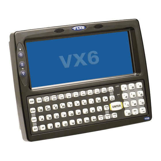
Components Top View 1. Access Panel Cover 2. Antenna Connectors or Hole Plugs Front View 1. Speakers 2. Control Panel 3. 2nd Indicator 4. Caps Lock Indicator... -
Page 7: Bottom View
Bottom View 1. COM1/Scanner Connector 2. COM3 Connector 3. Keyboard/Mouse Connector (Not Used) 4. Ethernet/USB Cable Connector (USB-Host and USB-Client) 5. Fuse 6. Audio Connector 7. Power Cable Connector Back View 1. Antenna Connectors 2. Bracket Mounting Area 3. Strain Relief Bracket and Screws... -
Page 8: Control Panel
Control Panel 1. Status / Power LED 2. Power Switch 3. Brightness Increase 4. Brightness Decrease Access Panel Note: Access Panel cover not shown. 1. SD Memory Card Slot 2. Compact Flash Hard Drive 3. PCMCIA Slots... -
Page 9: Chapter 2: Set Up A New Vx6
Chapter 2: Set Up A New VX6 This page lists a quick outline of the steps you might take when setting up a new VX6. More instruction for each step is listed later in this guide. Please refer to the VX6 Reference Guide for additional information and instruction. -
Page 10: Backlights And Indicators
Flashing Yellow - Running on UPS battery, battery is critically low. Keyboard LEDs The VX6 has two keyboard LEDs located above the Enter key and between the alpha keypad and the numerical keypad. CAPS LED This LED indicates the state of the keyboard CapsLock mode. If CapsLock is enabled this LED is illuminated green. When CapsLock is off, the LED is dark. -
Page 11: Tapping The Touch Screen With A Stylus
Tapping the Touch Screen with a Stylus Note: Always use the point of the stylus for tapping or making strokes on the touch screen. Never use an actual pen, pencil, or sharp/abrasive object to write on the touch screen. Hold the stylus as if it were a pen or pencil. Touch an element on the screen with the tip of the stylus then remove the stylus from the screen. -
Page 12: Attach Stylus Tether And Sleeve
Determine a convenient location for the stylus sleeve. Locate the most convenient tether mounting hole on the top of the VX6. Slide the clip end of the stylus tether into the tether mounting hole. -
Page 13: Using The Input Panel / Virtual Keyboard
Using the Input Panel / Virtual Keyboard The virtual keyboard is always available when needed e.g., text entry. Place the cursor in the text entry field and, using the stylus: Tap the Shift key to type one capital letter. Tap the CAPS key to type all capital letters. Tap the áü... -
Page 14: Touch Screen
Adjusting the Display Backlight Timer Start > Settings > Control Panel > Display > Backlight The backlight settings use the Honeywell set of default timeouts and are synchronized to the User Idle setting in the Schemes tab in the Power control panel. -
Page 15: Set Date And Time Zone
The GrabTime utility can be configured to synchronize the time with a local server during each reboot function. Tap the Sync button to synchronize date and time with a networked time server. By default, the VX6 operating system first searches for a time server on the local intranet. If not found, it then searches the Internet for a time server. A connection to the Internet is required for this option. -
Page 16: Adjust Speaker Volume
You can also select / deselect sounds for key clicks and screen taps and whether each is loud or soft. As the volume scroll bar is moved between Loud and Soft, the VX6 emits a tone each time the volume increases or decreases... -
Page 17: Setup Terminal Emulation Parameters
Setup Terminal Emulation Parameters Before you make a host connection, you will, at a minimum, need to know: the alias name or IP address (Host Address) and the port number (Telnet Port) of the host system to properly set up your host session. 1. -
Page 18: Using The Applock Switchpad
Click the switchpad icon in the taskbar. A checkmark on the switchpad menu indicates applications currently active or available for Launching by the VX6 user. When Keyboard, on the Switchpad Menu, is selected, the default input method (Input Panel, Transcriber, or custom input method) is activated. -
Page 19: Connecting Bluetooth Devices
The system administrator has also assigned a Computer Friendly Name using LXEZ Pairing Control Panel for the VX6. To connect Bluetooth devices, the VX6 should be as close as possible and in direct line of sight (distances up to 32.8 feet or 10 meters) with the targeted Bluetooth device during the discovery and pairing process. -
Page 20: Reboot
\Windows folder. Note: Because of the extreme nature of cold boot, Honeywell recommends using this command only as an emergency (or when instructed to do so as part of a specific VX6 procedure). The text typed in the text box can be upper or lower case or a combination of upper and lower case letters. -
Page 21: Connecting The Headset Cable
2. Headphones 3. Connects to voice cable end of voice cable Connect the VX6 voice cable I/O connector to the audio port on the VX6. The VX6 internal microphone and speaker are automatically disabled. Slide the voice cable ends together until they click shut. Do not twist or bend the connectors. -
Page 22: Adjust Headset / Microphone And Secure Cable
The headset consists of an earpiece, a microphone, a clothing clip and a cable. The headset attaches to the audio cable end of the voice cable which attaches to the VX6. Align the audio connector and the headset quick connect cable end. Firmly push the cable ends together until they click and lock in place. -
Page 23: Cleaning The Touch Screen
Cleaning the Touch Screen Note: These instructions are for components made of glass. If there is a removable protective film sheet on the display, remove the film sheet before cleaning the screen. Keep fingers and rough or sharp objects away from the bar code reader scanning aperture and the mobile device touch screen. If the glass becomes soiled or smudged, clean only with a standard household cleaner such as Windex®... -
Page 24: Startup Help
Technical Assistance if you need more help. Can’t change the date/time or AppLock is installed and may be running in User Mode on the VX6. AppLock user mode adjust the volume. restricts access to the control panels. Touch screen is not accepting See Also: "Calibrating the Touch... -
Page 25: Chapter 3: Connecting Cables To The Vx6
Connect Cable - Serial The printer or PC cable requires a nine-pin D-shell female connector for the VX6. The printer or PC cable is attached to the connector labeled COM2/3. Use of a shielded cable is required to maintain FCC and CISPR22 emissions compliance. -
Page 26: Connecting To Usb And Optional Ethernet Ports
Host port on the dongle cable . USB devices may be connected/ disconnected without turning off the VX6. 6. To connect the VX6 to a PC: Requires a commercially available USB cable with a type A plug on one end and a type B plug on the other end. -
Page 27: Connecting An Ac/Dc Power Supply
3. Plug cordset into appropriate, grounded, electrical supply receptacle (AC mains). 4. Connect the watertight connector end to the VX6’s Power Connector by aligning the connector pins to the power connector; pushing down on the watertight connector and twisting it to fasten securely. -
Page 28: Connecting Vehicle Power
Connecting Vehicle Power Complete vehicle cradle mounting and power instruction is contained in the VX6 Vehicle Mounting Reference Guide. Vehicle 12-80VDC Power Connection Cable Caution For proper and safe installation, the input power cable must be connected to a fused circuit on the vehicle. This fused circuit requires a ten Amp maximum time delay (slow blow) high interrupting rating fuse. - Page 29 8. Green Note: Correct electrical polarity is required for safe and proper installation. Connecting the cable to the VX6 with the polarity reversed will cause the VX6 fuse to be blown. See the following figure titled “Vehicle Connection Wiring Color Codes”...
-
Page 30: Connect Vehicle 12-80Vdc Connection
Connect Vehicle 12-80VDC Connection 1. The VX6 must be turned off and the power cable must be UNPLUGGED from the VX6. 2. While observing the fuse requirements specified above, connect the power cable as close as possible to the actual battery terminals of the vehicle. -
Page 31: Connect Vx6 Without A Ups Battery Pack
“Connect Vehicle 12-80VDC Connection”. 2. Connect the power cable to the VX6 by aligning the water-tight connector pins to the power connector on the bottom of the VX6; push down on the water-tight connector and twist it to fasten securely. -
Page 32: Connect Vx6 To An Integrated Mount Ups Battery Pack
3. Connect the output cable (labeled “To Computer”) from the UPS battery pack to the power connector on the bottom of the VX6 by aligning the water-tight connector to the power connector; push down on the water-tight connector and twist it to fasten securely. -
Page 33: Connect Vx6 To A Remotely Mounted Ups Battery Pack
Connect VX6 to a Remotely Mounted UPS Battery Pack A. Vehicle Battery B. Vehicle Power Connection Cable C. UPS Battery Pack D. Extension Cable E. VX6 Computer 1. Connect the power cable to the vehicle’s electrical system as described in Connect Vehicle 12-80VDC Connection. - Page 34 6. Connect the output end of the extension cable to the power connector on the bottom of the VX6 by aligning the water- tight connector to the power connector; push down on the water-tight connector and twist it to fasten securely.
-
Page 35: Power Adapter Cable
3. Connect the larger end of the Power Cable directly to the VX6 or to a UPS battery pack, as desired. Please refer to the... -
Page 36: Uninterruptible Power Supply Battery Pack
(such as when vehicle batteries are swapped). Fully charged, the UPS battery pack powers the VX6 for a minimum of 15 minutes at 25º C (77º F) ambient temperature. The Power Status LED on the VX6 indicates the UPS battery pack status: Green Running on 12V –... -
Page 37: Ups Battery Pack Remote Mounting Dimensions
UPS Battery Pack Remote Mounting Dimensions 1. 11.00” / 279.40mm 2. 10.23” / 259.80mm 3. 0.38” / 9.65mm 4. 1.39” / 35.31mm 5. 3.04” / 77.22mm 6. 0.30” / 7.62mm 3-13... -
Page 38: Connecting A Tethered Scanner
Pin 9 of COM1 must be configured to provide +5V. The scanner cable is attached to the connector labeled “COM1/SCANNER”. The tethered scanner receives power from the VX6. The cable requires a nine-pin D-shell female connector for the VX6. Note: Use of a shielded cable is required to maintain FCC and CISPR22 emissions compliance. -
Page 39: Chapter 4: Product Agency Compliance - Vx6
Li-Ion Battery When disposing of the VX6 main battery, the following precautions should be observed: The battery should be disposed of properly. The battery should not be disassembled or crushed. The battery should not be heated above 212°F (100°C) or... - Page 40 RF Notices This device contains transmitter Module FCC ID: KDZLXE4830P This device contains transmitter Module FCC ID: KDZLXE4831P RF Safety Notice This device is intended to transmit RF energy. For protection against RF exposure to humans and in accordance with FCC rules and Industry Canada rules, this transmitter should be installed such that a minimum separation dis- tance of at least 20 cm (7.8 in.) is maintained between the antenna and the general population.
-
Page 41: Lithium Battery Safety Statement
Lithium Battery Safety Statement Caution: Lithium battery inside. Danger of explosion if battery is incorrectly replaced. Replace only with same or equivalent type recommended by battery manufacturer. (US) Attention: Contient une pile de lithium. Risque d’explosion dans le cas où la pile ne serait pas correctement remplacée. Remplacer uniquement avec une pile semblable ou equivalente au type de pile recommandé... - Page 42 Lithium Battery Safety Statement, continued Legend: Chinese – CN; Danish – DK; Dutch – NL; English – US; Finnish – FI; French- - FR; German – DE; Greek – GR; Italian – IT; Japanese – JP; Korean – KR; Norwegian – NO; Portuguese – PT; Spanish – ES; Swedish – SE; Turkish – TR.
-
Page 43: Vehicle Power Supply Connection Safety Statement
Vehicle Power Supply Connection Safety Statement Vehicle Power Supply Connection: If the supply connection is made directly to the battery, a 10A slow-blow fuse should be installed in the positive lead within 5 inches (12.7 cm.) of the battery positive (+) terminal. (US) Raccordement de l’alimentation du véhicule Si l’alimentation est raccordée directement à... -
Page 45: Chapter 5: Technical Assistance
Limited Warranty Honeywell International Inc. ("HII") warrants its products to be free from defects in materials and workmanship and to conform to HII’s published specifications applicable to the products purchased at the time of shipment. This warranty does not cover any HII product which is (i) improperly installed or used;... - Page 46 The duration of the limited warranty for the VX6 external UPS battery is 1 year. The duration of the limited warranty for the VX6 AC power supply and cables is 1 year. The duration of the limited warranty for the VX6 DC-DC Converter is 1 year.
- Page 48 Honeywell Scanning & Mobility 9680 Old Bailes Road Fort Mill, SC 29707 www.honeywellaidc.com E-EQ-VX6OGWW Rev U 10/12...