Table of Contents
Advertisement
Advertisement
Table of Contents

Related Manuals for Rinnai REU-16


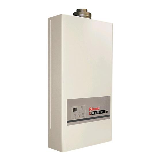
Summary of Contents for Rinnai REU-16
- Page 2 Quality System Standard ISO 9001 - 1994 The Design, Development, and Manufacture of Gas Water Heating Appliances done under Rinnai’s Quality Management System is certified under the Quality Management System Standard ISO 9001. Registration Number JQ0003D Registered since: February 1994...
- Page 3 UK INSTRUCTIONS This appliance may only be serviced or repaired by someone certified competent to do so. At the time of printing the only people deemed competent to install this appliance are those that are CORGI registered for this type of appliance in this type of location who have a current ACS certificate.
-
Page 4: Table Of Contents
Contents Contents………………………………………………………………..…………………4 Glossary of Terms and Symbols................5 Introduction......................6 Specification of 16i....................7 Sensors and Safety Devices..................8 Combustion Specifications..................8 Dimensions......................9 Schematic Diagram....................10 Structure Diagram....................11 Main Components....................12 Water Flow......................14 Water Pressure vs. Flow..................16 Gas Conversion Procedure..................17 Testing........................19 Gas Pressure Setting....................20 Dip Switch Setting....................22 Troubleshooting the Infinity 16i................23 Remotes.......................24 Operational Flow Chart..................25... -
Page 5: Glossary Of Terms And Symbols
Glossary of Terms and Symbols... -
Page 6: Introduction
The Rinnai Infinity hot water units represents the latest technology in continuous flow, temperature controlled hot water. Features The Rinnai Infinity 16i will NEVER RUN OUT of hot water. As long as electricity, • water, and gas supplies are connected, hot water is available when hot water taps are open. -
Page 7: Specification Of 16I
Specification of 16i Type of Appliance Temp Controlled Continuous Flow Gas Water Heater Operation With / Without remotes (Kitchen, Bathroom, etc.) Flue System Room Sealed, Forced Draught Flue Installation Internally Mounted only Available Temps 37C - 48C (1 deg Increments) 50, 55, 60 Width 370 mm Dimensions... -
Page 8: Sensors And Safety Devices
Sensors and Safety Devices • Heat Exchanger Thermistor: Measures hot water temperature at heat exchanger outlet. If water temperature reaches a predetermined limit, gas supply is stopped. • Hot Water Delivery Thermistor: Measures hot water temperature at the outlet valve (i.e. the ‘mixed’... -
Page 9: Dimensions
Dimensions... -
Page 10: Schematic Diagram
Schematic Diagram HOT WATER SUPPLY OPERATION Ignition Press ON/OFF Button of Optional Remote Control to turn on unit . The remote control display and priority LED will light up. When a hot water tap is opened the Water Flow Sensor revolves and sends a pulse signal to the Printed Circuit Board (PCB.) When the PCB detects a water flow over 2.4 L/min it compares the temperature at the Hot Water Thermistor to the set point and begins the ignition process;... -
Page 11: Structure Diagram
Structure Diagram... -
Page 12: Main Components
Main Components 1. Gas Control Unit 1.1 Modulating Valve This device is used by the PCB to adjust the volume of gas to the burner in proportion to the volumetric flow rate of water in order to maintain a supply of constant temperature hot water amid changes in water flow rates and incoming temperatures. - Page 13 Main Components 3. Thermal Fuse The thermal fuse is an electric link which must be intact for the unit to operate. If the thermal fuse reaches a set temperature it will melt and the unit will shut down. The thermal fuse must be replaced if it melts. It is to protect against over heating and heat exchanger splits where water may leak out and be superheated into steam.
-
Page 14: Water Flow
Water Flow The figures on the following page show the available water flow rates for different outlet temperatures based on a range of inlet temperatures. Regardless of the output capacity the maximum flow rate is limited to 20 litres/minute. Water Flows can also be calculated by the following formula: M = 60 x ( Q / C x T ) Where M = Water flow rate in litres/minute. - Page 15 Water Flow Incoming Water Temp 5C 2.4 L/min min Flow Hot Water Flowrate L/min Incoming Water Temp 10C 2.4 L/min min Flow Hot Water Flowrate L/min Incoming Water Temp 20C 20 L/min 2.4 L/min max Flow min Flow Hot Water Flowrate L/min...
-
Page 16: Water Pressure Vs. Flow
Regardless of how high the incoming water pressure is it is not possible to obtain more than 20 L/min from the Rinnai Infinity 16i. In order to have this much flow the temperature rise must be low enough that the unit has the capacity to satisfy the temperature setpoint for this flow rate. -
Page 17: Gas Conversion Procedure
Gas Conversion Procedure... - Page 18 Gas Conversion Procedure...
-
Page 19: Testing
Testing 1. Purge gas, hot water and cold water supply lines before making the final connection of the water heater. Swarf in either the gas or water supplies may cause damage. 2. Turn on gas and cold water supplies. 3. Test for water leaks and gas escapes near the unit. 4. -
Page 20: Gas Pressure Setting
Wait for the unit to light. Fig. 3 10.Set the Rinnai Infinity to 'Forced Low' combustion by setting No. 7 dipswitch to 'ON'. (Fig. 3) * Note: Simply changing the position of the dip switches will not convert the unit from one gas type to the other. - Page 21 Fig. 4 1.8 mbar Adjustment Point 2.2 mbar 2.2 mbar 13. Set the Rinnai Infinity to 'Forced High' combustion by setting no. 7 and no. 8 dipswitches to 'ON'. (Fig.5) Ensure maximum water flow. 14. Check the burner test point pressure.
-
Page 22: Dip Switch Setting
Dip Switch Setting Dip Switch Positions Explained OFF ON SW Gas Type LEGEND: Gas Type Black Section indicates Computer Programming position of dip switch. Computer Programming Computer Programming OFF ON OFF ON Max. Temperature Combustion Combustion Dip Switches Explained GAS TYPE COMBUSTION NAT GAS NORMAL... -
Page 23: Troubleshooting The Infinity 16I
* In all cases, you may be able to clear the Error code by turning the hot water tap OFF, then ON again. If this does not clear the error, try pushing the On/Off button OFF then ON again. If the Error Code still remains contact Rinnai or your nearest service agent for advice. -
Page 24: Remotes
Remotes Remote temperature controllers are a feature that provides control over the water temperature. The Rinnai Infinity 16i water heater can be operated with 1, 2, or 3 temperature controllers. The controller MC-45-SR-EU comes as standard with this water heater installed into the front panel. -
Page 25: Operational Flow Chart
Operational Flow Chart... -
Page 26: Time Charts
Time Charts... -
Page 27: Error Codes
Error Codes Error Fault Action Step Check flue terminal for blockages visual Combustion fan overcurrent. Unit Check Flue operates, then stops. Check combustion fan. Check Gas Supply is correct Check Gas Isolating Valves are open visual Check Electrode Check Flame Rod Missed or No Ignition. - Page 28 Error Codes Error Fault Action Step Make sure that if there is a controller, it is on visual Ensure there is enough water flow Check Filter Check for Air lock Check power cord is plugged in (if applicable) visual Check electrical supply is turned on visual Appliance does not operate at all.
-
Page 29: Diagnostic Checks
Diagnostic Checks A. Combustion Fan Circuit. The voltages should be checked while the unit has the electric power On. The meter leads can be inserted into the connection plug at the pcb (Plub B from wiring diagram.) To test the resistances electrically isolate the water heater, unplug the connector either at fan motor (B1) or at pcb (B), and measure the resistances through the motor. - Page 30 Diagnostic Checks If it is correct unplug the HT lead and hold it about 3 – 5 mm from a clean, earthed, screw head. WARNING: ISOLATE THE GAS SUPPLY. KEEP HANDS WELL AWAY FROM THE END OF THE LEAD – VERY HIGH VOLTAGES. Power the heater and turn the water on.
- Page 31 Diagnostic Checks D. Solenoid Valves. There are 3 solenoid valves and one modulating valve. Two of the solenoids are burner sectional solenoids, and the third is the main, safety solenoid. The easiest way to check the gas valve is by putting the manometer on the test point on the gas valve and cycling the unit.
- Page 32 Diagnostic Checks E. Thermal Fuse (Overheat) Circuit. First locate the Overheat circuit. It is made up of red wires making a loop through the unit, including a number of thermal fuses, and the overheat bi-metal switch. Along the right-hand side of the unit the red wires can be seen running down the side of the unit from the bi metal switch.
- Page 33 Diagnostic Checks G. Water Flow Servo Circuit. If the heater makes a loud ticking unplug the flow servo (motor behind the internal brass cold water inlet connection) and run the unit to see if it stops. If so the motor is faulty. Water Flow Servo Circuit.
- Page 34 Diagnostic Checks J. Water Flow Sensor. The water flow sensor is located inside the water heater immediately as the cold water enters the unit. From that there are 3 wires (red, yellow, black) running to the pcb, there is a connector plug in between the sensor and the pcb for testing. Measure the voltage with the water heater power on and no flow.
- Page 35 Diagnostic Checks Hot Water Outgoing Thermistor This thermistor is located at the bottom left of the water heater where the water exits the water heater. Combustion Air Thermistor This thermistor is located next to the controller connection point on the right hand side of the unit above the pcb.
- Page 36 Diagnostic Checks O. 3 Amp Fuses The unit has two 3 Amp fuses on the pcb and one in the moulded plug lead. Remove the fuses and check for continuity through. If there is continuity the fuse is good, if not replace it.
- Page 37 Diagnostic Checks R. Water flow. To operate there must be at least 2.4 l/min flowing through a Rinnai water heater. If there is multiple heaters, installed without PAM valves or a MECS system then there must be 2.4 l/min per heater. A modern wash hand basin could be as low as 3 or 4 l/ min, so if there is no means of staging the heaters they may not operate.
- Page 38 Diagnostic Checks Diagnostic Checks The rest of the circuit, including the valve heaters should be about 270 Ohms. Measure it by unconnecting the connector to the top heater and the connector to the hot water outlet valve heater and measure resistance through the sides of the connectors that lead to the valve heaters.
-
Page 39: Fault Finding Chart
Diagnostic Checks Fault Finding Chart... - Page 40 Fault Finding Chart...
- Page 41 Fault Finding Chart...
- Page 42 Fault Finding Chart...
- Page 43 Fault Finding Chart...
- Page 44 Fault Finding Chart...
- Page 45 Fault Finding Chart...
-
Page 46: Wiring Diagram
Wiring Diagram... -
Page 47: Diagnostic Points
Diagnostic Points Determination (normal figure) Measurement point Flow Component Upper : Voltage Remark Chart Wire Color Lower : Resistance, Current B-Br AC200~AC240V AC power GEARED Drive power ① DC11~13V MORTOR 10~30Ω R-Bk DC11~13V Control power Y-Bk Below DC1V(limiter ON) Full open limiter Below DC4~6V(limiter OFF) Br-Bk Below DC1V(limiter ON) -
Page 48: Servicing Procedure
Servicing Procedure Servicing Infinity Water Heaters Isolate electrics and valve off hot, cold, and gas to unit. Check the water filter and strainer to be sure there are no blockages. Remove the combustion fan and clean the impeller. Check the burner for wear or water damage. Vacuum out any debris. Wipe out chamber. -
Page 49: Dismantling For Service
Dismantling for Service... - Page 50 Dismantling for Service...
- Page 51 Dismantling for Service...
- Page 52 Dismantling for Service...
- Page 53 Dismantling for Service...
- Page 54 Dismantling for Service...
- Page 55 Dismantling for Service...
-
Page 56: Exploded Diagram
Exploded Diagram... - Page 57 Exploded Diagram...
- Page 58 Exploded Diagram...
- Page 59 Exploded Diagram...
- Page 60 Exploded Diagram...
-
Page 61: Parts List
Parts List... - Page 62 Parts List...
- Page 63 Parts List...
- Page 64 Parts List...
-
Page 65: Letter Of Compliance
Letter of Compliance... -
Page 66: Ce Certificate
CE Certificate...