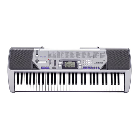
Casio CTK-496 Service Manual
Ctk-496
Hide thumbs
Also See for CTK-496:
- دليل االستخدام (92 pages) ,
- Product catalog (2 pages) ,
- User manual (45 pages)
Advertisement
Advertisement
Table of Contents

Related Manuals for Casio CTK-496


Summary of Contents for Casio CTK-496
- Page 1 CTK-496 JUN. 2004 CTK-496 ELECTRONIC KEYBOARD Ver.1 : Feb. 2005 INDEX...
-
Page 2: Table Of Contents
CONTENTS Specifications ---------------------------------------------------------------------------------------------- 1 Block Diagram --------------------------------------------------------------------------------------------- 3 Circuit Description --------------------------------------------------------------------------------------- 4 Printed Circuit Board ------------------------------------------------------------------------------------ 5 Disassembly ------------------------------------------------------------------------------------------------ 6 Diagnostic Program -------------------------------------------------------------------------------------- 7 Schematic Diagrams ----------------------------------------------------------------------------------- 12 Exploded View ------------------------------------------------------------------------------------------- 14 Parts List --------------------------------------------------------------------------------------------------- 15... -
Page 3: Specifications
12 notes maximum (6 for certain tones) Auto Accompaniment Rhythm Patterns: Tempo: Variable (236 steps, = 20 to 255) Chords: 2 fingering methods (CASIO CHORD, FINGERED) Rhythm Controller: START/STOP, SYNCHRO/FILL-IN Accomp Volume: 0 to 9 (10 steps) Song Bank Tunes:... - Page 4 ELECTRICAL Current drain with 9 V DC: 86 mA ± 20 % No sound output 650 mA ± 20 % Maximum volume with 13 keys C1 to C2 pressed in 60 Synth-Lead 1 Volume: Maximum, Velocity: Maximum Speaker output level (Vrms with 4 Ω load each channel): 1080 mV ±...
-
Page 5: Block Diagram
BLOCK DIAGRAM MIDI IN OUT Sustain Jack Keyboard KI1 ~ KI7 DB4 ~ DB7 LCD Driver LSI201 KO1 ~ KO7 LSI301 ST7066U-OAQ Power Switch KID0 ~ KID6 ML6756B24 KOD8 ~ KOD12 COM1 ~ COM7 SEG1 ~ SEG40 COM9 ~ COM16 Buttons OP AMP OP AMP... -
Page 6: Circuit Description
SYNCRO / KOD9 STOP FILL-IN BOOK VOLUME SONG TRANSPOSE/ KOD10 RHYTHM TONE BANK TUNE POWER / MODE POWER / MODE POWER / MODE POWER / MODE KOD11 (CASIO CHORD) (NORMAL) (OFF) (FINGERD) KOD12 RIGHT LEFT – PLAY/PAUSE STOP — 4 —... -
Page 7: Printed Circuit Board
PRINTED CIRCUIT BOARDS MAIN PCB M627-MAIN1 MIC VOLUME PCB M627-MAIN3 PCB MIC JACK PCB M627-MAIN2 Keyboard PCBs M627-KEY1/KEY2 — 5 —... -
Page 8: Disassembly
DISASSEMBLY 1. Remove the battery cover and the batteries. 2. Remove the volume knob. 3. Remove 12 screws on the bottom of the product, and three lower plates. Note: Fix the screws in the right order when assembling each lower plate. 4. - Page 9 Note: Pay attention to the position of the LED(D225) when assembling the upper case. 17.5 0.5 mm Note: Be careful of the height of the LED (D225) when replacing it. 6. Remove four solders and two speakers. Brown Orange Blue White 7.
- Page 10 8. Unsolder two lead wires for the power source. Unsolder one connector (CN1) and then remove the M627-MAA1 PCB. Power Cord (Black) Connector (CN1) Power Cord (Red) M627-MAA1 PCB 9. Remove 21 screws and the keys. 10. Remove five rubber keys on the keyboard. Note: The length of this one rubber key is different.
- Page 11 11. Unlock 17 hooks and remove the M627-KYA1 and M627-KY2 PCBs. Note: Make sure to lock all the hooks when assembling. M627-KYA1 PCB M627-KYA2 PCB — 9 —...
-
Page 12: Diagnostic Program
DIAGNOSTIC PROGRAM Message on LCD Initial Setting AD-5 1. Connect an AC adaptor. SP-2 2. Connect a Sustain pedal. NOTE: If there is no pedal or MIDI cable, pedal or MIDI check can be skipped. How to start diagnostic program 1. - Page 13 Message on LCD 6. MIDI check 1 Press “9” button. MIDI OK OK sound must ne audible. 7. PEDAL check 1 Press “RHYTHM” button. PED OFF 2 Press “Sus PEDAL” button. PED ON 8. LCD check 1 Press “TONE” button. Pip sound must be audible.
-
Page 14: Schematic Diagrams
SCHEMATIC DIAGRAMS MAIN PCB M420-MAIN1/MIC JACK PCB M420-MAIN2/MIC VOLUME PCB M420-MAIN3 — 12 —... - Page 15 Keyboard PCBs M627-KEY1/KEY2 — 13 —...
-
Page 16: Exploded View
EXPLODED VIEW 25 24 — 14 —... -
Page 17: Parts List
PARTS LIST CTK-496 Notes: This parts list does not include the cosmetic parts, which parts are marked with item No. "R-X" in the exploded view. Contact our spare parts department if you need these parts for refurbish. Prices and specifications are subject to change with- out prior notice. - Page 18 PARTS PRICE LIST CTK-496 Price Item Parts code Parts name Specification R Remarks Code Main PCB 1016 3666 PCB ASSY/MAA TK-RJM503927*001 D225 1010 7268 LED 1154HD-B5/7-90 J204 1008 1222 CONNECTOR HDC-052S-02 J203,205 6932 5081 CONNECTOR JY-6314-01-030 J201 6932 5082 CONNECTOR...
- Page 19 Ver.1 : Feb. 2005 Correction of the EXPLODED VIEW (P14) CASIO TECHNO CO.,LTD. Overseas Service Division 6-2, Hon-machi 1-Chome Shibuya-ku, Tokyo 151-8543, Japan...