Table of Contents
Advertisement
Advertisement
Table of Contents

Related Manuals for HYT TC-508


Summary of Contents for HYT TC-508
- Page 2 TC-508 Service Manual Contents Revision History .............................. 1 Copyright Information ............................. 1 Disclaimer................................. 1 Introduction..............................1 Product Controls ............................. 2 Software Specifications ..........................3 Circuit Description............................7 CPU Pins ................................. 13 Parts List 1 ..............................17 Tuning Description ............................72 Troubleshooting Flow Chart .........................
-
Page 3: Revision History
Initial Release Copyright Information HYT is the trademark or registered trademarks of Hytera Communications Co., Ltd. (“ Hytera” ) in PRC and/or other countries or areas. Hytera retains the ownership of its trademarks and product names. All other trademarks and/or product names that may be used in this manual are properties of their respective owners. -
Page 4: Product Controls
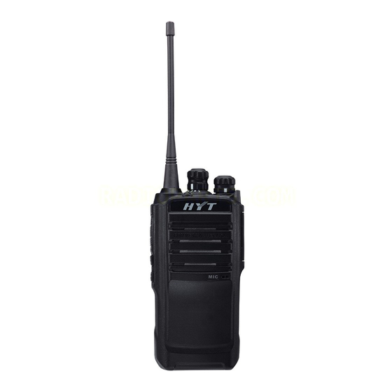
TC-508 Service Manual Product Controls Part Name Part Name Part Name ○ ○ ○ PTT Key SK1 (programmable) SK2 (programmable) Radio On-Off/Volume ○ ○ ○ Antenna Channel Selector Knob Control Knob ○ ○ ○ Speaker Microphone LED Indicator ○ ○... -
Page 5: Software Specifications
TC-508 Service Manual Software Specifications Status Indication Operations/Functions LED Indications and Alert Tones To enter Wired Clone Mode: Source radio: Power on the radio while during The LED on the source radio flashes red once holding down the power-on process. - Page 6 TC-508 Service Manual The LED glows red when the PC is reading data from the radio. Writing/Reading The LED glows green when the PC is writing data into the radio. A low-pitched tone sounds when the radio switches from high power to low power.
- Page 7 TC-508 Service Manual 2) During cloning, the LED of the source radio glows red, and the LED of the target radio glows green. When cloning finishes, both LEDs go out, indicating that both radios are ready for another cloning. 3) If any abnormal situation occurs during cloning, the source radio will stop cloning and its LED will flash orange, indicating that it is ready for another cloning.
- Page 8 TC-508 Service Manual The LED solidly glows green during RX group tuning (CH10 to CH13). The LED goes out upon invalid items (CH14 to CH16). 4. To switch between wide and narrow band Under a certain tuning item, long press the PTT key (the LED flashes orange to indicate valid press) to switch between wide and narrow bands.
-
Page 9: Circuit Description
TC-508 Service Manual Circuit Description 1. General Principle Diagram The general circuit is composed of TX circuit, RX circuit, power supply circuit, control circuit and etc. See the block diagram below: Figure 1 TX Section: The audio signal from MIC is sent to the MCU chip (U601) directly. The baseband signal... - Page 10 TC-508 Service Manual the newly generated signals will be processed by crystal filter XF501 to produce 38.85M the first IF signal. After being amplified, the IF signal goes via Q506 to the chip U611, where the IF signal will be mixed with the second local oscillator for the second time to produce the 450KHz second IF signal.
- Page 11 TC-508 Service Manual TX signal or RX first local oscillator signal. 2) VCO The VCO section is realized by the three-point capacitor oscillator circuit. TX VCO and RX VCO share the same oscillator circuit. Q103 controls the switch between TX VCO and RX VCO.
- Page 12 TC-508 Service Manual After the RF signals are received from the antenna, the undesired out-of-band signals are filtered out at the bandpass filter. Then the remaining RF signals are amplified by LNA Q501. Afterwards, the amplified signal goes through the bandpass filter again to eliminate undesired out-of-band interference signal.
- Page 13 TC-508 Service Manual 1) MCU Control Circuit MCU control circuit is composed of MCU, EEPROM, and keys, etc. This section has the following functions: to initialize data of the radio and save data to EEPROM; to detect battery voltage and signals from external keys, LD and VOX, and to make response;...
- Page 14 TC-508 Service Manual 2.5 Power Supply Section VR SW Q604 Q305 U606 V_SAVE U602 U604 V_BAT Figure 6 Power Supply Section: The 7.4V battery voltage is converted to 5V via DC-DC module U604, and further converted via LDO U602 to 3V including two channels: VCC and VDD. VCC powers CPU and VDD powers PLL circuit.
-
Page 15: Cpu Pins
TC-508 Service Manual CPU Pins Pin No. Port Name Pin Name Function UART TxD UART RxD APA_EN Speaker control pin (H: on; L: off) SAVE_CTL Battery save control pin. In non-battery-save status, it is set to high level. EXT MIC... - Page 16 TC-508 Service Manual CLD_OUTM Reserve Negative output of digital power amplifier Vdd_CLD VCC(3.0V) Power supply for digital power amplifier Reserve Reserved P76/DAC1 APC/TU TX power control/ RX bandpass control pin P75/VREF VCC(3.0V) ADC and DAC reference voltage input pin P74/DAC0...
- Page 17 TC-508 Service Manual P17/SEG7 Reserve Reserved P20/SEG8 P21/SEG9 For detecting encode switch input P22/SEG10 P23/SEG11 P24/SEG12 Reserve Reserved P25SEG13 Reserve Reserved P26/SEG14 Reserve Reserved P27/SEG15 Reserve Reserved P30/SEG16 Reserve Reserved P31/SEG17 Reserve Reserved P32/SEG18 Reserve Reserved P33/SEG19 Reserve Reserved P34/SEG20...
- Page 18 TC-508 Service Manual SW_P0 Reserve Reserved SW_P1 TX_CTRL TX power control pin (H: Transmit) RESET RESET Reset input pin Vssa Power ground for analog circuit Vdda VCC(3.0V) Power supply for analog circuit BG_REF Reference voltage output pin MIC_IN MIC_IN Microphone input pin...
-
Page 19: Parts List 1
TC-508 Service Manual Parts List 1 UHF1: 400-420MHz Part No. Description Qty Ref No. Print No. 3001050000000 Chip resistor 0Ω J 1/16W (RoHS) R222 3001050000000 Chip resistor 0Ω J 1/16W (RoHS) R402 3001050000000 Chip resistor 0Ω J 1/16W (RoHS) R442 3001050000000 Chip resistor 0Ω... - Page 20 TC-508 Service Manual Part No. Description Qty Ref No. Print No. 3001051020000 Chip resistor 1KΩ F 1/16W (RoHS) R691 3001051020000 Chip resistor 1KΩ F 1/16W (RoHS) R692 3001051020000 Chip resistor 1KΩ F 1/16W (RoHS) R693 3001051020000 Chip resistor 1KΩ F 1/16W (RoHS)
- Page 21 TC-508 Service Manual Part No. Description Qty Ref No. Print No. 3001052210000 Chip resistor 220Ω J 1/16W (RoHS) R126 3001052210000 Chip resistor 220Ω J 1/16W (RoHS) R201 3001052210000 Chip resistor 220Ω J 1/16W (RoHS) R516 3001052210000 Chip resistor 220Ω J 1/16W (RoHS)
- Page 22 TC-508 Service Manual Part No. Description Qty Ref No. Print No. 3001054720000 Chip resistor 4.7KΩ J 1/16W (RoHS) R608 3001054720000 Chip resistor 4.7KΩ J 1/16W (RoHS) R633 3001054730000 Chip resistor 47KΩ J 1/16W (RoHS) R106 3001054730000 Chip resistor 47KΩ J 1/16W (RoHS)
- Page 23 TC-508 Service Manual Part No. Description Qty Ref No. Print No. 3099080398000 Chip resistor 0.39Ω J 1/4W (RoHS) R419 3099080398000 Chip resistor 0.39Ω J 1/4W (RoHS) R420 3099080398000 Chip resistor 0.39Ω J 1/4W (RoHS) R421 3101050200010 Chip capacitor 2PF B 50V (RoHS)
- Page 24 TC-508 Service Manual Part No. Description Qty Ref No. Print No. 3101051010030 Chip capacitor 100PF J 50V(RoHS) C416 3101051010030 Chip capacitor 100PF J 50V(RoHS) C525 3101051010030 Chip capacitor 100PF J 50V(RoHS) C534 3101051010030 Chip capacitor 100PF J 50V(RoHS) C563 3101051010030...
- Page 25 TC-508 Service Manual Part No. Description Qty Ref No. Print No. 3101051030020 Chip capacitor 0.01UF K 25V(RoHS) C583 3101051030020 Chip capacitor 0.01UF K 25V(RoHS) C584 3101051030020 Chip capacitor 0.01UF K 25V(RoHS) C585 3101051030020 Chip capacitor 0.01UF K 25V(RoHS) C586 3101051030020 Chip capacitor 0.01UF K 25V(RoHS)
- Page 26 TC-508 Service Manual Part No. Description Qty Ref No. Print No. 3101054730000 Chip capacitor 0.047UF K 10V (RoHS) C207 3101051050000 Chip capacitor 1UF K 6.3V(RoHS) C321 3101051050000 Chip capacitor 1UF K 6.3V(RoHS) C590 3101051050000 Chip capacitor 1UF K 6.3V(RoHS) C627 3101051050000 Chip capacitor 1UF K 6.3V(RoHS)
- Page 27 TC-508 Service Manual Part No. Description Qty Ref No. Print No. 3101054710010 Chip capacitor 470PF K 50V (RoHS) C528 3101054710010 Chip capacitor 470PF K 50V (RoHS) C539 3101054710010 Chip capacitor 470PF K 50V (RoHS) C542 3101054710010 Chip capacitor 470PF K 50V (RoHS)
- Page 28 TC-508 Service Manual Part No. Description Qty Ref No. Print No. 3101062210000 Chip capacitor 220PF J 50V (RoHS) C427 3101051050160 Chip capacitor 1uF K 10V (RoHS) C218 3101051050160 Chip capacitor 1uF K 10V (RoHS) C555 3101062250000 Chip capacitor 2.2UF K 10V (RoHS)
- Page 29 TC-508 Service Manual Part No. Description Qty Ref No. Print No. 3221506601000 Bead 600Ω 100MHz ± 25% 500mA(RoHS) L527 3221506601000 Bead 600Ω 100MHz ± 25% 500mA(RoHS) L602 3221506601000 Bead 600Ω 100MHz ± 25% 500mA(RoHS) L606 3221506601000 Bead 600Ω 100MHz ± 25% 500mA(RoHS)
- Page 30 TC-508 Service Manual Part No. Description Qty Ref No. Print No. 3411002000020 NPN transistor 50V 150mA (RoHS) Q101 3411002000020 NPN transistor 50V 150mA (RoHS) Q611 3418001000010 NPN transistor 10V 50mA (RoHS) Q501 3499000000140 N-JFET VGS:15V VGSoff:-1.4V IDSS:50mA (RoHS) Q102 3499000000180 PNP transistor 12V 2.5A (RoHS)
- Page 31 TC-508 Service Manual Part No. Description Qty Ref No. Print No. 3001051240010 Chip resistor 120KΩ F 1/16W (RoHS) R632 3001051540000 Chip resistor 150KΩ F 1/16W (RoHS) R558 3001052710010 Chip resistor 270Ω J 1/16W (RoHS) R505 3001052710010 Chip resistor 270Ω J 1/16W (RoHS)
- Page 32 TC-508 Service Manual Part No. Description Qty Ref No. Print No. 3307110100130 LED 40mcd 30mA 2.1V (RoHS) D601 3101062240000 Chip capacitor 0.22UF K 10V (RoHS) C114 3101062240000 Chip capacitor 0.22UF K 10V (RoHS) C116 5205000001530 Battery connector black (RoHS) 3101074750010 Chip capacitor 4.7UF K 10V(RoHS)
- Page 33 TC-508 Service Manual Part No. Description Ref No. Print No. 3001051020000 Chip resistor 1KΩ F 1/16W (RoHS) R621 3001051020000 Chip resistor 1KΩ F 1/16W (RoHS) R626 3001051020000 Chip resistor 1KΩ F 1/16W (RoHS) R644 3001051020000 Chip resistor 1KΩ F 1/16W (RoHS) R650 3001051020000 Chip resistor 1KΩ...
- Page 34 TC-508 Service Manual Part No. Description Ref No. Print No. 3001051510000 Chip resistor 150Ω J 1/16W (RoHS) R115 3001051530000 Chip resistor 15KΩ J 1/16W (RoHS) R543 3001051540020 Chip resistor 150KΩ J 1/16W (RoHS) R523 3001051540020 Chip resistor 150KΩ J 1/16W (RoHS) R545 3001051820000 Chip resistor 1.8KΩ...
- Page 35 TC-508 Service Manual Part No. Description Ref No. Print No. 3001054700000 Chip resistor 47Ω J 1/16W (RoHS) R619 3001054710000 Chip resistor 470Ω J 1/16W (RoHS) R625 3001054720000 Chip resistor 4.7KΩ J 1/16W (RoHS) R112 3001054720000 Chip resistor 4.7KΩ J 1/16W (RoHS) R311 3001054720000 Chip resistor 4.7KΩ...
- Page 36 TC-508 Service Manual Part No. Description Ref No. Print No. 3001061540010 Chip resistor 150KΩ D 1/10W (RoHS) R425 3001061540010 Chip resistor 150KΩ D 1/10W (RoHS) R426 3001061540010 Chip resistor 150KΩ D 1/10W (RoHS) R427 3001070000000 Chip resistor 0Ω J 1/8W (RoHS) R326 3002991030160 Adjustable resistor 10K ±...
- Page 37 TC-508 Service Manual Part No. Description Ref No. Print No. 3101051010030 Chip capacitor 100PF J 50V C0G (RoHS) C121 3101051010030 Chip capacitor 100PF J 50V C0G (RoHS) C122 3101051010030 Chip capacitor 100PF J 50V C0G(RoHS) C124 3101051010030 Chip capacitor 100PF J 50V C0G(RoHS)
- Page 38 TC-508 Service Manual Part No. Description Ref No. Print No. 3101051030020 Chip capacitor 0.01UF K 25V X7R (RoHS) C322 3101051030020 Chip capacitor 0.01UF K 25V X7R(RoHS) C437 3101051030020 Chip capacitor 0.01UF K 25V X7R(RoHS) C540 3101051030020 Chip capacitor 0.01UF K 25V X7R(RoHS) C541 3101051030020 Chip capacitor 0.01UF K 25V X7R(RoHS)
- Page 39 TC-508 Service Manual Part No. Description Ref No. Print No. 3101051040060 Chip capacitor 0.1UF K 16V X7R(RoHS) C547 3101051040060 Chip capacitor 0.1UF K 16V X7R(RoHS) C548 3101051040060 Chip capacitor 0.1UF K 16V X7R(RoHS) C576 3101051040060 Chip capacitor 0.1UF K 16V X7R(RoHS) C577 3101051040060 Chip capacitor 0.1UF K 16V X7R(RoHS)
- Page 40 TC-508 Service Manual Part No. Description Ref No. Print No. 3101054710010 Chip capacitor 470PF K 50V X7R (RoHS) C406 3101054710010 Chip capacitor 470PF K 50V X7R (RoHS) C407 3101054710010 Chip capacitor 470PF K 50V X7R (RoHS) C408 3101054710010 Chip capacitor 470PF K 50V X7R (RoHS)
- Page 41 TC-508 Service Manual Part No. Description Ref No. Print No. 3101054720000 Chip capacitor 4700PF K 50V X7R (RoHS) C647 3101054720000 Chip capacitor 4700PF K 50V X7R (RoHS) C675 3101054740020 Chip capacitor 0.47uF K 10V X5R (RoHS) C537 3101054740020 Chip capacitor 0.47uF K 10V X5R (RoHS)
- Page 42 TC-508 Service Manual Part No. Description Ref No. Print No. 3210305220000 Multi-layer chip inductor 22nH J 300mA 0.42ohm 402 (RoHS) L505 3210305220000 Multi-layer chip inductor 22nH J 300mA 0.42ohm 402 (RoHS) L525 3212106221000 Multi-layer chip inductor 220nH J 300mA 0.4ohm 603 (RoHS) L108 3210306561010 Multi-layer chip inductor 560nH K 35mA 1.55ohm 603 (RoHS)
- Page 43 TC-508 Service Manual Part No. Description Ref No. Print No. 3304180000000 Varactor 15V 9.3~21pF 2.2 (RoHS) D513 3304180000000 Varactor 15V 9.3~21pF 2.2 (RoHS) D514 3304180000000 Varactor 15V 9.3~21pF 2.2 (RoHS) D515 3305180300000 variable resistance diode 100mA max 1Ω (RoHS) D401 3307110100060 LED 200mcd 30mA 1.9V (RoHS)
- Page 44 TC-508 Service Manual Part No. Description Ref No. Print No. 3001055620000 Chip resistor 5.6KΩ J 1/16W (RoHS) R540 3001056840000 Chip resistor 680KΩ J 1/16W (RoHS) R541 3001057540000 Chip resistor 750KΩ J 1/16W (RoHS) R547 3101051520000 Chip capacitor 1500PF K 50V X7R (RoHS) C569 3603018000000 IF processor 10~150MHZ 1.8~5.5V SSOP-B16 (RoHS)
- Page 45 TC-508 Service Manual Part No. Description Ref No. Print No. 3101061200000 Chip capacitor 12PF J 50V C0G (RoHS) C418 3101061300000 Chip capacitor 13PF J 50V COG (RoHS) C438 3101060400010 Chip capacitor 4PF B 50V C0G (RoHS) C130 3101060400010 Chip capacitor 4PF B 50V C0G (RoHS)
- Page 46 TC-508 Service Manual UHF3: 430-450MHz Part No. Description Qty Ref No. Print No. 3001050000000 Chip resistor 0Ω J 1/16W (RoHS) R222 3001050000000 Chip resistor 0Ω J 1/16W (RoHS) R442 3001050000000 Chip resistor 0Ω J 1/16W (RoHS) R511 3001050000000 Chip resistor 0Ω J 1/16W (RoHS) R533 3001050000000 Chip resistor 0Ω...
- Page 47 TC-508 Service Manual Part No. Description Qty Ref No. Print No. 42 3001051020000 Chip resistor 1KΩ F 1/16W (RoHS) R696 43 3001051020000 Chip resistor 1KΩ F 1/16W (RoHS) R697 44 3001051020000 Chip resistor 1KΩ F 1/16W (RoHS) R698 45 3001051030000 Chip resistor 10KΩ J 1/16W (RoHS) R103 46 3001051030000 Chip resistor 10KΩ...
- Page 48 TC-508 Service Manual Part No. Description Qty Ref No. Print No. 85 3001052220010 Chip resistor 2.2KΩ F 1/16W (RoHS) R202 86 3001052220010 Chip resistor 2.2KΩ F 1/16W (RoHS) R216 87 3001052220010 Chip resistor 2.2KΩ F 1/16W (RoHS) R310 88 3001052220010 Chip resistor 2.2KΩ F 1/16W (RoHS) R327 89 3001052220010 Chip resistor 2.2KΩ...
- Page 49 TC-508 Service Manual Part No. Description Qty Ref No. Print No. 128 3001054730000 Chip resistor 47KΩ J 1/16W (RoHS) R312 129 3001054730000 Chip resistor 47KΩ J 1/16W (RoHS) R320 130 3001054730000 Chip resistor 47KΩ J 1/16W (RoHS) R417 131 3001054730000 Chip resistor 47KΩ J 1/16W (RoHS) R553 132 3001054730000 Chip resistor 47KΩ...
- Page 50 TC-508 Service Manual Part No. Description Qty Ref No. Print No. 171 3101050400010 Chip capacitor 4PF B 50V COG (RoHS) C568 172 3101050400010 Chip capacitor 4PF B 50V COG (RoHS) C573 173 3101050500010 Chip capacitor 5PF B 50V COG (RoHS)
- Page 51 TC-508 Service Manual Part No. Description Qty Ref No. Print No. 214 3101051020010 Chip capacitor 1000PF K 50V X7R (RoHS) C113 215 3101051020010 Chip capacitor 1000PF K 50V X7R (RoHS) C120 216 3101051020010 Chip capacitor 1000PF K 50V X7R (RoHS)
- Page 52 TC-508 Service Manual Part No. Description Qty Ref No. Print No. 257 3101051030020 Chip capacitor 0.01UF K 25V X7R (RoHS) C612 258 3101051030020 Chip capacitor 0.01UF K 25V X7R (RoHS) C617 259 3101051030020 Chip capacitor 0.01UF K 25V X7R (RoHS) C635 260 3101051030020 Chip capacitor 0.01UF K 25V X7R (RoHS)
- Page 53 TC-508 Service Manual Part No. Description Qty Ref No. Print No. 300 3101051500020 Chip capacitor 15PF J 50V COG (RoHS) C639 301 3101051590000 Chip capacitor 1.5PF B 50V (RoHS) C558 302 3101052200010 Chip capacitor 22PF J 50V C0G (RoHS) C107...
- Page 54 TC-508 Service Manual Part No. Description Qty Ref No. Print No. 343 3101054710010 Chip capacitor 470PF K 50V X7R (RoHS) C582 344 3101054710010 Chip capacitor 470PF K 50V X7R (RoHS) C593 345 3101054710010 Chip capacitor 470PF K 50V X7R (RoHS)
- Page 55 TC-508 Service Manual Part No. Description Qty Ref No. Print No. 386 3101064790010 Chip capacitor 4.7PF B 50V COG (RoHS) C112 387 3101082260020 Chip capacitor 22UF M 10V X5R (RoHS) C329 388 3104074750070 Tantalum capacitor 4.7UF M 10V (RoHS) C128 389 3104074750070 Tantalum capacitor 4.7UF M 10V (RoHS)
- Page 56 TC-508 Service Manual Part No. Description Qty Ref No. Print No. 429 3221507600000 Bead 60Ω 100MHz ± 25% 3000mA (RoHS) L410 430 3231351640000 Air-core inductor E2-0.35*1.6*4TL (RoHS) L412 431 3231351640000 Air-core inductor E2-0.35*1.6*4TL (RoHS) L413 432 3231351640000 Air-core inductor E2-0.35*1.6*4TL (RoHS) L414 433 3231351640000 Air-core inductor E2-0.35*1.6*4TL (RoHS)
- Page 57 TC-508 Service Manual Part No. Description Qty Ref No. Print No. 472 3503020000030 N-MOSFET VDS:30V ID:100mA VGS(th):3.0V (RoHS) Q202 473 3503020000030 N-MOSFET VDS:30V ID:100mA VGS(th):3.0V (RoHS) Q304 474 3504990000010 Power amplifier VDS:30V ID:600mA VGS(th):1.8V 1.4W (RoHS) Q402 475 3605008005070 Operational amplifier 3~32V 300mW 100dB (RoHS) U401 476 3605017005540 Operational amplifier 1.8~15V 220mW 39dB (RoHS)
- Page 58 TC-508 Service Manual Part No. Description Qty Ref No. Print No. 515 3104071060080 Tantalum capacitor 10UF M 6.3V (RoHS) C132 516 3104072250060 Tantalum capacitor 2.2UF M 10V (RoHS) C518 517 3210305150010 Multi-layer chip inductor 15nH J 300mA 0.32ohm 402(RoHS) R441 518 3001061050010 Chip resistor 1MΩ...
- Page 59 TC-508 Service Manual Part No. Description Qty Ref No. Print No. 558 3210108230010 Wire-wound inductor 23nH J 590mA 0.046ohm (RoHS) L104 559 3101053330000 Chip capacitor 0.033UF K 16V X7R (RoHS) C207 560 3101054090010 Chip capacitor 4PF B 50V COG (RoHS)
- Page 60 TC-508 Service Manual Part No. Description Qty Ref No. Print No. 23 3001051010040 Chip resistor 100Ω F 1/16W(RoHS) R131 24 3001051010040 Chip resistor 100Ω F 1/16W(RoHS) R429 25 3001051010040 Chip resistor 100Ω F 1/16W(RoHS) R604 26 3001051010040 Chip resistor 100Ω F 1/16W(RoHS) R605 27 3001051010040 Chip resistor 100Ω...
- Page 61 TC-508 Service Manual Part No. Description Qty Ref No. Print No. 65 3001051040000 Chip resistor 100KΩ F 1/16W(RoHS) R205 66 3001051040000 Chip resistor 100KΩ F 1/16W(RoHS) R513 67 3001051040000 Chip resistor 100KΩ F 1/16W(RoHS) R517 68 3001051040000 Chip resistor 100KΩ F 1/16W(RoHS) R518 69 3001051040000 Chip resistor 100KΩ...
- Page 62 TC-508 Service Manual Part No. Description Qty Ref No. Print No. 107 3001053320000 Chip resistor 3.3KΩ J 1/16W(RoHS) R130 108 3001053320000 Chip resistor 3.3KΩ J 1/16W(RoHS) R203 109 3001053320000 Chip resistor 3.3KΩ J 1/16W(RoHS) R204 110 3001053320000 Chip resistor 3.3KΩ J 1/16W(RoHS) R431 111 3001053320000 Chip resistor 3.3KΩ...
- Page 63 TC-508 Service Manual Part No. Description Qty Ref No. Print No. 149 3001054740000 Chip resistor 470KΩ J 1/16W(RoHS) R548 150 3001054740000 Chip resistor 470KΩ J 1/16W(RoHS) R549 151 3001054790000 Chip resistor 4.7Ω J 1/16W(RoHS) R318 152 3001055610000 Chip resistor 560Ω J 1/16W(RoHS) R118 153 3001055620000 Chip resistor 5.6KΩ...
- Page 64 TC-508 Service Manual Part No. Description Qty Ref No. Print No. 191 3101051000020 Chip capacitor 10PF J 50V(RoHS) C117 192 3101051000020 Chip capacitor 10PF J 50V(RoHS) C136 193 3101051000020 Chip capacitor 10PF J 50V(RoHS) C137 194 3101051000020 Chip capacitor 10PF J 50V(RoHS)
- Page 65 TC-508 Service Manual Part No. Description Qty Ref No. Print No. 233 3101051020010 Chip capacitor 1000PF K 50V(RoHS) C413 234 3101051020010 Chip capacitor 1000PF K 50V(RoHS) C417 235 3101051020010 Chip capacitor 1000PF K 50V(RoHS) C462 236 3101051020010 Chip capacitor 1000PF K 50V(RoHS)
- Page 66 TC-508 Service Manual Part No. Description Qty Ref No. Print No. 275 3101051030020 Chip capacitor 0.01UF K 25V(RoHS) C559 276 3101051030020 Chip capacitor 0.01UF K 25V(RoHS) C562 277 3101051030020 Chip capacitor 0.01UF K 25V(RoHS) C565 278 3101051030020 Chip capacitor 0.01UF K 25V(RoHS) C576 279 3101051030020 Chip capacitor 0.01UF K 25V(RoHS)
- Page 67 TC-508 Service Manual Part No. Description Qty Ref No. Print No. 317 3101051050000 Chip capacitor 1UF K 6.3V(RoHS) C680 318 3101051200020 Chip capacitor 12PF J 50V(RoHS) C414 319 3101051200020 Chip capacitor 12PF J 50V(RoHS) C517 320 3101051200020 Chip capacitor 12PF J 50V(RoHS)
- Page 68 TC-508 Service Manual Part No. Description Qty Ref No. Print No. 359 3101054710010 Chip capacitor 470PF K 50V(RoHS) C411 360 3101054710010 Chip capacitor 470PF K 50V(RoHS) C424 361 3101054710010 Chip capacitor 470PF K 50V(RoHS) C426 362 3101054710010 Chip capacitor 470PF K 50V(RoHS)
- Page 69 TC-508 Service Manual Part No. Description Qty Ref No. Print No. 401 3101060600010 Chip capacitor 6PF B 50V(RoHS) C429 402 3101060600010 Chip capacitor 6PF B 50V(RoHS) C431 403 3101060600010 Chip capacitor 6PF B 50V(RoHS) C433 404 3101060900010 Chip capacitor 9PF B 50V(RoHS)
- Page 70 TC-508 Service Manual Part No. Description Qty Ref No. Print No. 443 3210305101000 Multi-layer chip inductor100nH J 150mA 1.25ohm(RoHS) L418 444 3210305101000 Multi-layer chip inductor100nH J 150mA 1.25ohm(RoHS) L526 445 3210305150010 Multi-layer chip inductor15nH J 300mA 0.32ohm(RoHS) L419 446 3210305220000 Multi-layer chip inductor22nH J 300mA 0.42ohm(RoHS) L417 447 3210305220000 Multi-layer chip inductor22nH J 300mA 0.42ohm(RoHS)
- Page 71 TC-508 Service Manual Part No. Description Qty Ref No. Print No. 485 3231351660000 Air-core inductor E2-0.35*1.6*6TR(RoHS) L426 486 3231351670000 Air-core inductor E2-0.35*1.6*7TR(RoHS) L425 487 3231351680000 Air-core inductor E2-0.35*1.6*8TR(RoHS) L409 488 3231351680000 Air-core inductor E2-0.35*1.6*8TR(RoHS) L501 489 3302030500020 Zener diode 18V (RoHS) D655 490 3303030300000 Schottky barrier diode 40V 30mA 0.26V/1mA(RoHS)
- Page 72 TC-508 Service Manual Part No. Description Qty Ref No. Print No. 527 3503010000010 P-MOSFET VDS:-30V ID:-100mA VGS(th):-1.9V(RoHS) Q106 528 3503010000010 P-MOSFET VDS:-30V ID:-100mA VGS(th):-1.9V(RoHS) Q604 529 3503020000030 N-MOSFET VDS:30V ID:100mA VGS(th):3.0V(RoHS) Q202 530 3503020000030 N-MOSFET VDS:30V ID:100mA VGS(th):3.0V(RoHS) Q304 531 3504990000010 Power amplifier MOSFET VDS:30V ID:600mA VGS(th):1.8V 1.4W(RoHS) Q402 532 3504990000040 Power amplifier MOSFET 10uA 25V 10uA 7.2V 7W (RoHS)
- Page 73 TC-508 Service Manual Part No. Description Qty Ref No. Print No. 569 3101062400010 Chip capacitor 24PF J 50V(RoHS) C430 570 3101062400010 Chip capacitor 24PF J 50V(RoHS) C449 571 3101063300000 Chip capacitor 33PF J 50V(RoHS) C418 572 3101065600000 Chip capacitor 56PF J 50V(RoHS) C451 573 3210108470000 Wire-wound inductor 47nH J 380mA 0.11ohm(RoHS)
-
Page 74: Tuning Description
TC-508 Service Manual Tuning Description Required Test Instruments Radio communication test set (HP8921) 1 set 10V/3A regulated DC power supply 1 set Digital voltmeter 1 set Ammeter 1 set Preparation Place the board to be tested on the test fixture (please ensure good connection between each test point and the fixture), and connect the board to a power supply with DC voltage of 7.4V. - Page 75 TC-508 Service Manual Measurement Tuning Specification Item Condition Test Test Part Method s / Remarks Instrument Point Tune VR101 with ceramic tuning tool to Set to CH1, and Antenna Frequenc Communicatio control the ≤150Hz hold down PTT to connecto VR101...
- Page 76 TC-508 Service Manual power, and Short press PTT to rotate the switch among Channel different Selector frequencies (low, knob to save medium and high). Set to CH3. At this time, “ wide bandwidth” “ low frequency”are selected. Make the Short press PTT to...
- Page 77 TC-508 Service Manual on each channel Press On CH5, CH6, and key to CH7, long press make slight PTT to enter narrow Narrow 300 - tuning until the Band band, short 500Hz CTCSS press PTT to switch deviation meets frequencies.
- Page 78 TC-508 Service Manual switch narrow band. Set to CH10 and Tune the SQL On 5. Press output signals SK1 or SK2 key to Communicati of SSG to the sample the current on test set squelch level. value. At this time,...
- Page 79 TC-508 Service Manual value, finally given with rotate the red LED Channel flashing. Selector knob to save it. Communicati Check the Rotate the CH13 (low on test set bandpass Volume frequency). SSG: waveform, Control and use SK1 -119dBm knob to a...
-
Page 80: Troubleshooting Flow Chart
TC-508 Service Manual Troubleshooting Flow Chart TX Circuit Start Low TX LED fails to Replace No sound power transmission glow/flash. D604. Normal TX Check the TX power supply? power supply. Check the voice channel LED of D604 TX VCO Check the... - Page 81 TC-508 Service Manual RX Circuit Start No signal received Check the RX The RX circuit is power supply normally supplied? circuit. The RX LED works The RX frequency is Change the RX normally? set correctly ? frequency. The RX signaling is set...
- Page 82 TC-508 Service Manual Start Normal power-on alert? The speaker Replace the works normally? speaker. Normal VCC Check U601, (operating voltage of U602, U604 and MCU)? U606. Clock crystal (X601) of MCU works Replace X601. normally? Check pin Other pins control...
-
Page 83: Disassembly And Assembly
TC-508 Service Manual Disassembly and Assembly Disassembling the chassis Remove the Antenna, Channel Selector knob and Radio On-Off/Volume Control knob. Unscrew the nuts for the channel selector knob and the volume control knob. Unscrew the two screws with a screwdriver at the bottom of the radio. - Page 84 TC-508 Service Manual Screw 螺钉 喇叭 Speaker 压片 fixing sheet Figure 9 Disassembling the PCB 1. Loosen the screw ⑥ (fixing the PCB) and ⑦ (fixing the PTT keypad). Then unsolder the antenna connector. 2. Remove the main board ⑧ from the chassis.
- Page 85 TC-508 Service Manual Assembling the radio unit 1. Insert the speaker into the front case properly. 2. Insert the speaker fixing sheet into the front case, and fix it with a screw. 3. Make sure the antenna sleeve is properly attached.
-
Page 86: Exploded View
TC-508 Service Manual Exploded View... -
Page 87: Parts List 2
TC-508 Service Manual Parts List 2 Part No. Description Qty. Front case (RoHS) 6001139000000 6100312000010 (RoHS) PTT key (silicone rubber) 6000842100010 PTT key (plastic) (RoHS) Self-tapping screw (RoHS) 7101904020200 Main PCB board (RoHS) Waterproof ring for radio (RoHS) 6100542100000 Aluminum chassis (RoHS) -
Page 88: Packing Guide
TC-508 Service Manual Packing Guide... -
Page 89: Pcb View
TC-508 UHF PCB View Top Layer... - Page 90 TC-508 UHF PCB View Bottom Layer...
- Page 91 TC-508 VHF PCB View Top Layer...
- Page 92 TC-508 VHF PCB View Bottom Layer...
-
Page 93: Level Diagram
TC-508 UHF/VHF Level Diagram TC-508 u5^sVþ -122dBm -121dBm -123dBm -107dBm -104dBm -115dBm -104dBm MIXER BPF1 ANT LPF Q501 BPF2 Q502 AT41511 2SK318 IF1 AMP IF1 FILLER Q506 XF501 38.85MHz RX Part -3dBm 2450mVrms -100dBm 240mVrms DEMODULATING IC 130mVrms AF LEVEL... -
Page 94: Block Diagram
TC-508 UHF/VHF Block Diagram TC-508 SŸ t hFVþ B201 SP_JACK PJ-D3027D VR SW POWER AMP POWER AMP D405 Q402 Q403 POWER AMP LOCAL OSCILLATOR AMP AF AMP RD01 RD07 Q401 Q406 U302 2SC4226 2SC4226 MICJACK POWER AF_SW ANT LPF MATCH... -
Page 95: Schematic Diagram
TC-508 UHF Schematic Diagram (MCU&POWER) TC-508 U(2) (450MHZ-470MHZ) 原理图(MCU&POWER) Q304 Q304 R327 R327 2SK1824 2SK1824 R323 R323 SPK- SPK- SPK+ SPK+ C331 C331 TP109 TP109 TP108 TP108 1000P 1000P C321 C321 R310 R310 R332 R332 2.2K 2.2K R325 R325 R324 R324 0.1u... - Page 96 TC-508 UHF Schematic Diagram (PLL&RX) TC-508 U(2) (450MHZ-470MHZ) 原理图(PLL&RX) L527 L527 L523 L523 RX_TL R519 R519 601s 601s 601s 601s C525 C525 C578 C578 C579 C579 R516 R516 C521 C521 C524 C524 470P 470P 0.01u 0.01u L506 L506 0.1U 0.1U...
- Page 97 TC-508 UHF Schematic Diagram (TX&VCO) TC-508 U2 (450MHZ-470MHZ) 原理图(TX&VCO) L416 L416 C459 C459 R440 R440 C409 C409 R441 R441 C414 C414 C404 C404 L408 L408 C416 C416 W401 W401 C425 C425 C427 C427 C431 C431 C433 C433 C429 C429 1.5k 1.5k...
- Page 98 TC-508 VHF Schematic Diagram (MCU&POWER) Q304 Q304 V2 (146-174MHz) 原理图(MCU&POWER) R327 R327 TC-508/500S 2SK1824 2SK1824 SPK- SPK- SPK+ SPK+ C331 C331 TP109 TP109 1000P 1000P TP108 TP108 C321 C321 R310 R310 2.7K 2.7K U302 U302 C326 C326 TDA2822D TDA2822D R316...
- Page 99 TC-508 VHF Schematic Diagram (PLL&RX) 原理图(PLL&RX) TC-508/500S V2 (146-174MHz) RX_TL L527 L527 R519 R519 510R 510R L523 L523 601s 601s C525 C525 601s 601s C578 C578 C579 C579 R516 R516 100P 100P C521 C521 C524 C524 470P 470P 0.01u 0.01u...
- Page 100 TC-508 VHF Schematic Diagram (TX&VCO) 原理图(TX&VCO) TC-508 /500S V2(146-174MHz) W401 W401 C409 C409 C414 C414 C429 C429 C404 C404 C405 C405 L408 L408 C416 C416 C425 C425 C433 C433 C427 C427 C431 C431 R440 R440 ANTENNA ANTENNA 1000P 1000P 100p...
-
Page 101: Specifications
TC-508 Service Manual Specifications General UHF1: 400-420MHz UHF2: 450-470MHz Frequency Range UHF3: 430-450MHz VHF: 146-174MHz Channel Capacity Channel Spacing 25KHz/ 12.5KHz Operating Voltage 7.4V Battery 1650mAh Li-Ion battery Battery Life (5-5-90 Duty Cycle) 14 hours ℃ Operating Temperature -25 ~+ 60℃... - Page 102 8130050800100...