
Related Manuals for Carrier AC310


Summary of Contents for Carrier AC310
- Page 1 Transport Air Conditioning OPERATION AND SERVICE MODELS AC310 & AC350 Rooftop Air Conditioning Units With BT324 Carrier Sutrak Digital Display (CSDD) 280P/282P Electronic Thermostat T--304 Rev A Change 07/09...
-
Page 2: Air Conditioning Unit
OPERATION AND SERVICE MANUAL TRANSPORT AIR CONDITIONING UNIT MODELS AC310 & AC350 ROOFTOP AIR CONDITIONING UNITS *CSDD - - BT324 (*Carrier Sutrak Digital Display) Electronic Thermostat - - 280P & 282P... -
Page 3: Table Of Contents
....... . . 1--7 1.2.8 CSDD BT--324 (Carrier--Sutrak Digital Display) Microprocessor ...... - Page 4 TABLE OF CONTENTS Continued: Operating Instructions BT324 ............3--2 3.4.1 Display .
- Page 5 ............1--2 Figure 1--2 Condensing Section Components (AC310 -- Dual Loop -- GEN I) ......
- Page 6 LIST OF TABLES Table 1--1 AC310 Models ...............
-
Page 7: Safety Summary
SAFETY SUMMARY GENERAL SAFETY NOTICES The following general safety notices supplement the specific warnings and cautions appearing elsewhere in this manual. They are recommended precautions that must be understood and applied during operation and maintenance of the equipment covered herein. A listing of the specific warnings and cautions appearing elsewhere in the manual follows the general safety notices. - Page 8 The Filter-drier May Contain Liquid Refrigerant. Slowly Loosen The Connecting Nuts And Avoid Contact With Exposed Skin Or Eyes. CAUTION The AC310 & AC350 Rooftop Systems have R134a service port couplings installed on the compres- sor and 1/4 inch flare (Acme) fittings installed on the unit piping. CAUTION To prevent trapping liquid refrigerant in the manifold gauge set be sure set is brought to suction pressure before disconnecting.
-
Page 9: Description
Manual (280P) 77--62032--05 12 VDC BT324 *77--62032--06 12 VDC BT324 (Tropic) *NOTE: 77--62032--06 (Tropic) -- Has an AC310 Evaporator Section & an AC350 Condenser Section. Table 1- -2 AC 350 Models Part Number Voltage Controller With Heat Dual Loop Single Loop... -
Page 10: General Description
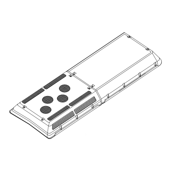
AC310 AC350 Evaporator Section Condenser Section Figure 1- -1 AC310/350 Rooftop Units 1.2.2 Condensing Section than refrigerant circulating inside the tubes; this results in condensation of the refrigerant into a liquid. The The dual (See Figure 1--2) and single loop (See... - Page 11 Condenser Fan and Motor Assembly Service Valve (High Side) Condenser Motor Support Filter Drier Upper Support Discharge Line Check Valve (Location) Filter Drier Figure 1- -2 Condensing Section Components (AC310 - - Dual Loop - - GEN I) T--304 04/08 1--3...
-
Page 12: Evaporator Section
(to add in--dash service port), and condensate drain connections. The dual loop AC310 & AC350 (GEN I) evaporator The liquid line solenoid valve closes when the system is section (See Figure 1--4) includes the evaporator coils,... - Page 13 Dual Loop Evaporator Coil Assembly Sight Glass Heater Coil Heating Line Expansion Valve Access Port Evaporator Blower Assembly Liquid Line Solenoid Evaporator Motor Figure 1- -4 Evaporator Section Components (AC310 - -Dual Loop - - GEN I) T--304 04/08 1--5...
-
Page 14: Drivers Evaporator (Optional)
Single Loop Compressors 05G & 05K The drivers evaporator assembly is normally installed in The 05G (AC350) & 05K (AC310) compressor the vehicle dash area and interfaces with the rooftop unit assemblies used with the single loop units, includes the electrical cabeling and refrigerant piping. -
Page 15: System Operating Controls And Components
AC310 - - Single Loop TM- -31 Compressor nents 12 Pounds (5.4 kg) without In--Dash unit AC310 - - Single Loop 05G or 05K Compressor The system is operated by an electronic thermostat type 13.2 to 15.4 Pounds (6.0 to 7.0 kg) without controller and/or manually operated switches. -
Page 16: Safety Devices
& some TM31’s, the pressure switches are not Heating circuit (See Figure 1--7) components furnished located on the compressors. They are installed by Carrier Transport Air Conditioning include the heater cores and solenoid operated heat valves. Components in--line. furnished by the bus manufacturer may include a water temperature switch (WTS) and boost water pump. -
Page 17: Figure 1--6 Refrigerant Flow Diagram -- Cooling (Dual Loop)
Driver’s Evaporator Thermal Expansion Valve Subcooler Liquid Line Sight Glass Compressor (TM--21 or A--6) Service Port Service Valve Liquid Line Solenoid Condenser Coil Evaporator Coil Filter--Drier Heat Coil Receiver Note: Items 1 through 12 are typical, both systems. Figure 1- -6 Refrigerant Flow Diagram - - Cooling (Dual Loop) T--304 04/08 1--9... - Page 18 SUPPLY RETURN Heat Coil Heat Solenoid Valve Vehicle Radiator Optional Hand Valve Boost Pump Figure 1- -7 Flow Diagram - - Heating NOTE: In order to ensure water is entering the heater coils sufficiently heated, it is suggested that the OEM supplied Water Temperature Switch (WTS) close on temperature rise at 150°F (65.5°C). T--304 04/08 1--10...
-
Page 19: Figure 1--8 Refrigerant Flow Diagram, Cooling (Single Loop) Ac350
Discharge Liquid Relief Valve Suction Coolant CONDENSER Discharge Check Valve Dash Air Suction Line Dash Air Liquid Line EVAPORATOR Figure 1- -8 Refrigerant Flow Diagram, Cooling (Single Loop) AC350 Thermal Expansion Valve Compressor Liquid Line Sight Glass Service Valve Service Port R134a Condenser Coil Service Port 1/4 Flare (Acme) 10. -
Page 20: Figure 1--9 Sheet 1 -- Electrical Control Board (280P)
Ref. Sutrac 60- -01- -21- -062 CLR1 CLR2 Ref. Sutrak Schematic 65- -01- -28- -056- -01- -3 See Figure 1- -9 Sheet 2 Legend Figure 1- -9 Sheet 1 - - Electrical Control Board (280P) T--304 04/08 1--12... -
Page 21: Figure 1--9 Sheet 2 Legend
LEGEND V1, Diode, Dash Switch F1M, Fuse, Evaporator Motor V2, Diode, Dash Switch F2M, Fuse, Evaporator Motor V3, Diode, Dash Switch F3M, Fuse, Evaporator Motor V4, Diode, Thermostat, Cooling F4M, Fuse, Evaporator Motor V5, Diode, Thermostat, Heating F5M, Fuse, Evaporator Motor Thermostat F6M, Fuse, Evaporator Motor Return Air Sensor... -
Page 22: Figure 1--10 Ac350 With Bt324 Control
1..K1A = Compressor Clutch -- Liquid Line Solenoid -- Condenser Fans 2..K2A = Heat Valve -- Boost Pump 3..K3A = Evaporator Fans 4..K1M -- K6M = Individual Evaporator Fans (M1M -- M6M) 5..K7M -- K9M = Individual Condenser Fans (M21M -- M26M) 6..Fuse = Boost Pump &... -
Page 23: Figure 1--11 Motor Fault Board (Optional)
POWER 10- - 30V OPEN CIRCUIT MOTOR POWER DS13 EVAP1 POWER DS14 EVAP2 DS15 EVAP3 DS25 DS16 EVAP4 DS17 GROUND EVAP5 DS18 EVAP6 DS19 EVAP7 DS20 EVAP8 DS21 COND1 DS22 DS10 COND2 DS23 DS11 COND3 DS24 DS12 COND4 X1--1 MOTOR EVAP1 WHT/RED BREAKER... -
Page 24: Operation (Manual Controller)
If the engine is not running, start the engine. b. Actual start sequence depends on the operating co- The control switches supplied by Carrier Transport Air trol supplied. If only an ON/OFF switch is supplied, Conditioning will be marked with international symbols place the switch in the ON (fan symbol) position to (See Figure 2.1). -
Page 25: Modes Of Operation
(High Ambient) 3.6°F. from the set point. The compressor clutch is disengaged at this time. 2.3.7 Override Mode - - AC310 (Dehumidification) 2.3.6 Compressor Unloader Control (Only with When in the heat mode the compressor will not operate. 05G or 05K Compressors) The thermostat will allow only COOL, VENT or HEAT modes independently. -
Page 26: Evaporator Fan Speed Selection
2.3.8 Evaporator Fan Speed Selection 4. Through line U3, to energize the condenser fan re- lays (K14M & K15M). Energizing these relays will Evaporator fan speed(s) selection is one method of send B+ power to start the condenser fan motors. controlling the cooling and heating throughout the bus The unit is now in low speed cooling. -
Page 27: Operation Bt324 Controller
(See Figure 3--1). A 150 Amp @12 VDC or a125 Amp @ 24 VDC fuse in The BT324 Carrier Sutrak Digital Display (CSDD) is the battery compartment passes power for the clutch, marked with international symbols (See Figure 3--2). -
Page 28: Sequence Of Operation Bt324 Csdd
Figure 3- -2 BT324 CSDD Controller KEYS LEDS Plus Key Display Minus Key Fresh Air Operation (Green) Recirculate/Fresh Air Key Manual Blower Control ’ON’ (Green) Blower Control Key Heating Mode (Green) Automatic Climate Control (A/C) Malfunction Light (Red) 3.3 SEQUENCE OF OPERATION BT324 CSDD NOTE The following blower steps are disabled when 3.3.1 Function of Keys when “Engine On”... -
Page 29: Reheat (Optional)
However, the blowers may be switched to manual mode A sensor malfunction is displayed by “i - -- -” or “o - -- -”. of operation by pressing the blower key. 3.5 CHANGING BETWEEN °F (FAHRENHEIT) Press the Plus or Minus keys to define one of 5 different AND °C (CELCIUS ) blower steps. -
Page 30: Troubleshooting
SECTION 4 TROUBLESHOOTING Table 4- -1 General System Troubleshooting Procedures INDICATION - - REFERENCE POSSIBLE CAUSES TROUBLE SECTION System Will Not Cool Compressor will not run Drive--Belt loose or defective Check Clutch coil defective Check/Replace Clutch malfunction Check/Replace Compressor malfunction See Table 1--3 Electrical malfunction Coach power source defective... -
Page 31: No Evaporator Air Flow Or Restricted Air Flow
Table 4- -1 General System Troubleshooting Procedures - - Continued INDICATION - - REFERENCE POSSIBLE CAUSES TROUBLE SECTION Abnormal Noise Or Vibrations - - Continued Condenser or evaporator fans Loose mounting hardware Check/Tighten Defective bearings Replace Blade interference Check Blade missing or broken Check/Replace No Evaporator Air Flow Or Restricted Air Flow Air flow through coil blocked... -
Page 32: Service
To avoid damage to the earth’s ozone layer, use a refrigerant recovery system whenever removing refriger- ant. The refrigerant recovery system is available from Carrier Transicold (Carrier Transicold P/N MVSII--115 or MVSII--240). When working with refrigerants you must comply with all local goverment environmental laws. -
Page 33: Installing R--134A Manifold Gauge/Hose Set
SUCTION CAUTION PRESSURE PRESSURE GAUGE GAUGE The AC310 & AC350 Rooftop Systems have R134a service port couplings installed on the compressor and 1/4 inch flare (Acme) fittings installed on the unit piping. CLOSED OPENED 5.4.1 Installing R- -134a Manifold Gauge/Hose SET... -
Page 34: Pumping The System Down Or Removing The Refrigerant Charge
5.5 PUMPING THE SYSTEM DOWN OR REMOV- ING THE REFRIGERANT CHARGE NOTE To avoid damage to the earth’s ozone layer, use a refrigerant recovery system whenever remov- ing refrigerant. 5.5.1 System Pump Down For Low Side Repair To Compressor To service or replace the filter--drier, pump the refrigerant to the condenser and receiver as follows: a. -
Page 35: Preparation
The presence of moisture in a refrigeration system can d. Under the above conditions, the system is properly have many undesirable effects. The most common are charged when the liquid line sight glase shows full (no copper plating, acid sludge formation, “freezing-up” of bubbles present). -
Page 36: Checking High Or Low Pressure Switches
5.10.2 Checking High Or Low Pressure Switches 5.11 FILTER-DRIER WARNING Do not use a nitrogen cylinder without a pres- sure regulator Figure 5- -5 Filter- -Drier Removal Filter-Drier Inlet Liquid Line WARNING Service Valve Solenoid Valve Valve Service Port Filter-Drier Outlet Flare Nut Service Valve Do not use oxygen in or near a refrigeration sys-... -
Page 37: Servicing The Heat Valve
It is not necessary to drain the coolant from the sys- Valve is normally located outside of the tem. AC310/350 rooftop air conditioning system. b. Place main battery disconnect switch in OFF position and lock. There are only three possible valve malfunctions: coil c. -
Page 38: Coil Replacement
Failure to open may be caused by the following: 1. Coil burned out or an open circuit to coil connections. 2. Improper voltage. 3. Defective plunger or deformed valve body assembly. Failure to close may be caused by the following: 1. -
Page 39: Replacing Return Air Filters
5.15 REPLACING RETURN AIR FILTERS f. Pull filter element approximately 1/4 inch over ends of the diffuser. The return air filters are located behind the return air Diffuser grill, inside the vehicle. The filters should be checked for cleanliness periodically depending on operating conditions. A dirty filter will restrict air flow over the evaporator coil which may cause insufficient cooling or heating and possible frost buildup on the coil. -
Page 40: Valve Replacement
Figure 5- -14 Thermostatic Expansion Valve Bulb and Thermocouple 1.. Suction Line 4.. Thermocouple Figure 5- -13 Thermostatic Expansion Valve (section view) 5.. TXV Bulb (Shown 1.. Power Head 4.. Gasket 2.. TXV Bulb Clamp in the 4’clock Assembly 5.. Cage Assembly 3.. - Page 41 j. The superheat may cycle from a low to high reading. readings taken to determine average superheat. The superheat should be 18 ± 3°F. Monitor the superheat taking readings every 3--5 min- utes for a total of 5--6 readings. Calculate the super- heats, add the readings and divide by the number of k.
-
Page 42: Table 5--1 R-134A Temperature - Pressure Chart
Table 5- -1. R-134a Temperature - Pressure Chart Temperature Vacuum Temperature Pressure ° ° ° ° “/hg cm/hg kg/cm@ psig kg/cm@ --40 --40 14.6 49.4 37.08 0.49 24.5 168.9 1.72 1.69 26.1 180.0 1.84 1.80 12.3 41.6 31.25 0.42 27.8 191.7 1.95 1.92... -
Page 43: Electrical
Figure 6--7 thru Figure 6--13 shows the CSDD BT324 schematics shown in this section provides information controller used with the AC310 single and dual systems for the AC310 and AC350 model rooftop air conditioning and the AC350 single loop with transit compressors. - Page 44 T--304 6--2 04/08...
- Page 45 04/08 T--304 6--3...
- Page 46 T--304 6--4 04/08...
- Page 47 04/08 T--304 6--5...
- Page 48 T--304 6--6 04/08...
- Page 49 04/08 T--304 6--7...
- Page 50 T--304 6--8 04/08...
- Page 51 04/08 T--304 6--9...
- Page 52 T--304 6--10 04/08...
- Page 53 04/08 T--304 6--11...
- Page 54 SUTRAK SCHMATIC #65, 01, 28, 056--01--3 T--304 6--12 04/08...
- Page 55 04/08 T--304 6--13...
- Page 56 T--304 6--14 04/08...
- Page 57 04/08 T--304 6--15...
- Page 58 T--304 6--16 04/08...
- Page 59 04/08 T--304 6--17...
- Page 60 T--304 6--18 04/08...
- Page 61 04/08 T--304 6--19...
- Page 62 INDEX Maintenance Schedule, 5--1 Air Filters, 5--7 Manifold Gauge Set, 5--1 Apex Unit, 1--2 Modes Of Operation, 2--2 Circuit Breaker, 1--8 Noncondensibles, 5--4 Clutch, 2--3 Compressor, 1--6, 1--7 Compressor Clutch Control, 2--3 Operating Controls, 1--7 Condenser Fan, 1--8 Operating Instructions, 2--1, 3--1 Condensing Section, 1--2 OPERATION, 2--1, 3--1 Cooling Mode, 2--2...
- Page 63 Carrier Corporation Fax: 1- -717- -764- -0401 Transport Air Conditioning Group P.O. Box 4805 Syracuse, N.Y. 13221 U.S A www.carrier.transicold.com A member of the United Technologies Corporation family. Stock symbol UTX ©2008 Carrier Corporation D Printed in U. S. A. 0408...