Table of Contents
Advertisement
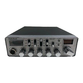
TRC-447
40-CHANNEL MOBILE CB
WITH WX ALERT
Catalog Number: 21-1576
CONTENTS
Page
Specifications ................................................................................................................................................. 2
Block Diagram ................................................................................................................................................ 5
Alignment And Adjustment ............................................................................................................................. 6
Troubleshooting ........................................................................................................................................... 10
Wiring Diagram ............................................................................................................................................ 16
Printed Circuit Boards .................................................................................................................................. 17
Exploded View And Disassembly Instructions .............................................................................................. 20
Mechanical Parts List ................................................................................................................................... 23
Electrical Parts List ...................................................................................................................................... 24
Semiconductor Lead Identification ............................................................................................................... 43
Ic Internal Diagrams .................................................................................................................................... 44
Ic And Transistor Voltage Chart ................................................................................................................... 46
Schematic Diagrams .................................................................................................................................... 50
2004 RadioShack Corporation.
All Rights Reserved.
RadioShack is a registered trademark of RadioShack Corporation.
Advertisement
Table of Contents

Related Manuals for Radio Shack TRC-447


Summary of Contents for Radio Shack TRC-447
- Page 1 TRC-447 40-CHANNEL MOBILE CB WITH WX ALERT Catalog Number: 21-1576 CONTENTS Page Specifications ..............................2 Block Diagram ..............................5 Alignment and Adjustment ..........................6 Troubleshooting ............................10 Wiring Diagram ............................16 Printed Circuit Boards ..........................17 Exploded View and Disassembly Instructions ....................20 Mechanical Parts List ...........................
-
Page 2: Specifications
SPECIFICATIONS GENERAL Channels: 40 (CB Transceiver) 7 (Digital Weather Alert Radio) Frequency range: 26.965 MHz to 27.405 MHz (CB) 162.400 MHz to 162.550 MHz (WX) Frequency control: PLL controlled synthesizer Microphone: Electret condenser type microphone with channel up/down switch Antenna impedance: 50-ohm Controls: Volume control with Power on/off Switch... - Page 3 CB TRANSMITTER PORTION Item Unit Nominal Limit ±200 ±1300 Frequency tolerance 25 °C 13.8 V − RF Power output AMC range 50% to 100% modulation −3 −10 Modulation frequency response Lower frequency 450 Hz −3 −10 Upper frequency 2500 Hz Microphone sensitivity 1 kHz, 50% Mod.
- Page 4 CHANNEL FREQUENCY OF PLL SYNTHESIZER CB BAND WX/ALERT BAND Antenna TX VCO RX VCO Antenna Frequency Frequency Frequency Frequency Frequency (MHz) (MHz) (MHz) (MHz) (MHz) 26.965 26.965 16.270 162.400 151.705 26.975 26.975 16.280 162.425 151.730 26.985 26.985 16.290 162.450 151.755 27.005 27.005 16.310...
-
Page 5: Block Diagram
BLOCK DIAGRAM — 5 —... -
Page 6: Alignment And Adjustment
ALIGNMENT AND ADJUSTMENT ALIGNMENT OF PLL Test Equipment Required and Connections • DC power supply: 13.8 V • DC voltmeter • Dummy load (50-ohm) Dummy Load (50-ohm) And Attenuator DC Voltmeter J501 JACK J751 Alignment Procedure Step Preset to Adjustment Remarks TX 40 CH L301... -
Page 7: Alignment Procedure
ALIGNMENT OF TRANSMITTER SECTION Test Equipment Required and Connections • DC power supply: 13.8 V • Modulation meter • AF oscillator • RF power meter • Dummy load (50-ohm) & attenuator Dummy Load (50-ohm) AF Oscillator RF Power Meter And Attenuator Modulation Meter Transceiver 10 F... - Page 8 ALIGNMENT OF RECEIVER SECTION Test Equipment Required and Connections • DC power supply: 13.8 V • AC voltmeter • Dummy load (8-ohm, 5 W resistive) • Signal generator (SG) (27.205 MHz, 1 kHz, 30% AM modulation, output inpedance 50-ohm): CB (162.45 MHz, 1 kHz, ±3kHz Dev.
- Page 9 Alignment Point Locations (Main PCB) FUSE 13.8v(RED) GND(BLK) DC CORD J501 DC JACK J502 L7 L1 L103 RT101 — 9 —...
-
Page 10: Troubleshooting
TROUBLESHOOTING SYSTEM CONTROL SECTION CLOCK Unit will not tum on Power ON Check the Fuse. Replace Fuse. Check the voltage of IC502. Check the power Replace IC502. SW VR601. Is display normal? Check the voltage Replace IC502. at IC502. Check the oscillation at pin 26 of IC401. - Page 11 AUDIO SECTION sound Check if speaker wiring is Replace or resolder. connected properly. Check if volume, squelch controls are adjusted properly. Check volume and Replace wire or resolder. wire connections. Adjust volume and squelch control. Check IC501 Replace IC501 AF power IC AF power IC and Q10.
-
Page 12: Pll Circuit
PLL CIRCUIT CB No good Check whether there is RF voltage at R58 (L7 side). Check whether there is RF voltage at pin11 of IC301. Check whether there is approx. 2.3 V at CH1 (RX) and Defective R10, L101, C152 3.8 V at CH40 (TX) at TP3. - Page 13 PLL CIRCUIT WX No good Check the voltage of TP4 approx. 1 to 4V at CH1~7. Check the voltage Defective Vcc line at R316 reading at pin 15 of or D303. IC301 is approx. 5 V. Check if there is RF Defective xtal X301 or poor voltage at pin 16 soldering.
- Page 14 RX SECTION CHECK Does not receive. Check ANT jack. Replace J501. If C If WX/Digital SAME. RF GAIN VOL MAX. Replace Check the voltage D201. D201. Check whether there is RF See PLL section. voltage at TP7 and 2nd Local. Check the voltage of TP4 1 to 4V See PLL section.
- Page 15 TX SECTION CHECK Does not transmit Defective or bad contact in Check the CB/WX antenna connector, or defective switch and the CB/WX switch. connections. Check whether TX LED turns on. Check the voltage at pin 1 of IC401. Check the voltage at pin 10 of IC401.
-
Page 16: Wiring Diagram
WIRING DIAGRAM — 16 —... -
Page 17: Printed Circuit Boards
PRINTED CIRCUIT BOARDS Main Top View — 17 —... - Page 18 Bottom View — 18 —...
- Page 19 SWITCH/VOLUME/LED/MIC/CH SW/SWR PCBs Top View Bottom View — 19 —...
-
Page 20: Exploded View And Disassembly Instructions
EXPLODED VIEW AND DISASSEMBLY INSTRUCTIONS To remove the Top and Bottom Covers: Remove eight screws 20-3 from the both sides of Top and Bottom Covers (see page 22). 20-5 20-8 20-7 20-6 20-7 20-4 20-2 — 20 —... - Page 21 20-1 — 21 —...
- Page 22 20-3 20-9 20-3 20-12 20-11 20-5 20-10 20-14 20-13 20-12 — 22 —...
-
Page 23: Mechanical Parts List
MECHANICAL PARTS LIST Ref. No. Description RS Part No. Mfr’ s Part No. Shield Case SPTE,T=0.3 HSDC453000Z Shield Plate SPTE HSDC454315Z Cushion NEOPRENE SP 25*15*15T RCUN435264Z Holder: PCB SECC HHDZ4B5754Z Panel, Front GCAS2B5626Z Display Window GCAS442091Z Holder, Meter POLYETHY,MILK WHITE GHDM404812Z Holder, LED GHDZ442085Z... -
Page 24: Electrical Parts List
ELECTRICAL PARTS LIST MAIN PCB ASSEMBLY Ref. No. Description RS Part No. Mfr’s Part No. Assembly, MAIN PCB AT367ZHBA Consists of the following: Capacitors Notes: All ceramic capacitors are Multilayer (1608) Tape type, unless otherwise specified. The following codes indicate variations of capacitors against temperature: B=±10%, CH=0±60 ppm/°C, UJ=−750 ppm/°C±120 ppm/°C, CK=0 ±250 ppm/°C, F=+30 −80 %, ±5 %... - Page 25 Ref. No. Description RS Part No. Mfr’s Part No. ±5 % Ceramic 100 pF 50 V BCMM811014Z 0.001 µF 50 V ±10 % Ceramic BCML811025Z ±5 % Ceramic 150 pF 50 V BCMM811514Z 0.001 µF 50 V ±10 % Ceramic BCML811025Z 0.022 µF 25 V ±10 %...
- Page 26 Ref. No. Description RS Part No. Mfr’s Part No. 0.047 µF 50 V ±10 % C132 Ceramic BCML814735Z 0.001 µF 50 V ±10 % C133 Ceramic BCML811025Z 0.01 µF ±10 % C134 Ceramic 50 V BCML811035Z C135 Not Used 2.2 µF ±20 % C136 Electrolytic...
- Page 27 Ref. No. Description RS Part No. Mfr’s Part No. 0.022 µF 25 V ±10 % C229 Ceramic BCML512235Z ±5 % C230 Ceramic 150 pF 50 V BCMM811514Z 0.0047 µF 50 V ±10 % C231 Ceramic BCML814725Z 22 µF ±20 % C232 Electrolytic 50 V...
- Page 28 Ref. No. Description RS Part No. Mfr’s Part No. 0.1 µF ±10 % C334 Ceramic 16 V BCML311045Z 0.001 µF 50 V ±10 % C335 Ceramic BCML811025Z 0.1 µF ±10 % C336 Ceramic 16 V BCML311045Z 0.1 µF −20+80 % F C337 Ceramic 25 V...
- Page 29 Ref. No. Description RS Part No. Mfr’s Part No. D101 HSM88AS BDAY0346001 D102~104 Not Used D105 1N4148 T-77 AX TS 26+ BDAY0246003 D106 1N4148 T-77 AX TS 26+ BDAY0246003 D107~200 Not Used D201 Switching 1SS356 TW11 BDAY0808001 D202 Switching 1SS356 TW11 BDAY0808001 D203...
- Page 30 Ref. No. Description RS Part No. Mfr’s Part No. Coil LB-1030 K7T1/33333 BLBY1030001 LB-1029 K7-H5/33333 BLBY1029001 LB-1103 M7-M/33303 BLBY1103001 LB-1028 K7-H5/33333 BLBY1028001 LB-652 M7-M/33334 BLBY0652001 LB-652 M7-M/33334 BLBY0652001 LB-1030 K7T1/33333 BLBY1030001 1 µH K L101 Inductor Molded LZ-041 BLZY0041109 L102 Inductor Molded Chip Tape LZ-183 HK1608R10J-T 100NH...
- Page 31 Ref. No. Description RS Part No. Mfr’s Part No. Q104 DB-848 2SC5065-Y(TE85R) BDBC5065124 Q201 DB-792 2SC2314F BDBC2314106 Q202 DB-301 2SC941TM-O TAPING RH TS+ BDBX0941523 Q203 DB-718 2SC2714-Y TE85L BDBC2714124 Q204 DB-862 2SC3052-T12-1F BDBC3052106 Q205 DB-092 2SA1235A-T12-1F BDBA1235106 Q206 DB-862 2SC3052-T12-1F BDBC3052106 Q207 DB-862...
- Page 32 Ref. No. Description RS Part No. Mfr’s Part No. 150 kohm 1/16 W ±5 % Carbon Fixed Chip BRFC161544Z 68 kohm 1/16 W ±5 % Carbon Fixed Chip BRFC166834Z 150 kohm 1/16 W ±5 % Carbon Fixed Chip BRFC161544Z ±5 % Carbon Axial Lead (26) 2.2 kohm 1/6 W BRPA612224Z 330 ohm 1/16 W ±5 %...
- Page 33 Ref. No. Description RS Part No. Mfr’s Part No. 10 kohm 1/16 W ±5 % Carbon Fixed Chip BRFC161034Z 47 kohm 1/16 W ±5 % Carbon Fixed Chip BRFC164734Z 47 kohm 1/16 W ±5 % Carbon Fixed Chip BRFC164734Z 2.2 kohm 1/16 W ±5 % Carbon Fixed Chip BRFC162224Z 2.2 Mohm 1/16 W ±5 %...
- Page 34 Ref. No. Description RS Part No. Mfr’s Part No. 1.8 kohm 1/16 W ±5 % R151 Carbon Fixed Chip BRFC161824Z 1/16 W ±5 % R201 Carbon Fixed Chip 1 kohm BRFC161024Z 680 ohm 1/16 W ±5 % R202 Carbon Fixed Chip BRFC166814Z 2.2 kohm 1/16 W ±5 % R203...
- Page 35 Ref. No. Description RS Part No. Mfr’s Part No. 22 kohm 1/16 W ±5 % R311 Carbon Fixed Chip BRFC162234Z 10 kohm 1/16 W ±5 % R312 Carbon Fixed Chip BRFC161034Z 47 kohm 1/16 W ±5 % R313 Carbon Fixed Chip BRFC164734Z 10 kohm 1/16 W ±5 % R314...
- Page 36 Ref. No. Description RS Part No. Mfr’s Part No. 1/16 W ±5 % R451 Carbon Fixed Chip 1 kohm BRFC161024Z 1/16 W ±5 % R452 Carbon Fixed Chip 1 kohm BRFC161024Z 1/16 W ±5 % R453 Carbon Fixed Chip 1 kohm BRFC161024Z 1/16 W ±5 % R454...
- Page 37 Ref. No. Description RS Part No. Mfr’s Part No. Wire UL 1430 #24 10- 50- 3 BLK CUFK005041Z Wire UL 1430 #24 5-210- 3 BRN CUFA021021Z Wire UL 1430 #24 5-210- 3 RED CUFB021021Z Miscellaneous PCB:Main (Not repairable) PA-432AA BPAY0432AA1 Test Pin TP-122 1820-01-PP1...
- Page 38 Switch PCB ASSEMBLY Ref. No. Description RS Part No. Mfr’s Part No. Assembly, Switch PCB B551 AT367ZHBB Consists of the following: Capacitors Notes: All ceramic capacitors are Multilayer (1608) Tape type, unless otherwise specified. The following codes indicate variations of capacitors against temperature: B=±10% Flat Cable FC551...
- Page 39 Volume PCB ASSEMBLY Ref. No. Description RS Part No. Mfr’s Part No. Assembly, Volume PCB B601 AT367ZHBC Consists of the following: Capacitors Notes: All ceramic capacitors are Multilayer (1608) Tape type, unless otherwise specified. The following codes indicate variations of capacitors against temperature: B=±10% Flat Cable FC601...
- Page 40 LED PCB ASSEMBLY Ref. No. Description RS Part No. Mfr’s Part No. Assembly, LED PCB B701 AT367ZHBD Consists of the following: Capacitors Notes: All ceramic capacitors are Multilayer (1608) Tape type, unless otherwise specified. The following codes indicate variations of capacitors against temperature: B=±10% 0.01 µF ±10 %...
- Page 41 MIC PCB ASSEMBLY Ref. No. Description RS Part No. Mfr’s Part No. Assembly, MIC PCB B751 AT367ZHBE Consists of the following: Capacitors Notes: All ceramic capacitors are Multilayer (1608) Tape type, unless otherwise specified. The following codes indicate variations of capacitors against temperature: B=±10% Flat Cable FC751...
- Page 42 SWR PCB ASSEMBLY Ref. No. Description RS Part No. Mfr’s Part No. Assembly, SWR PCB B851 AT367ZHBG Consists of the following: Capacitors Notes: All ceramic capacitors are Multilayer (1608) Tape type, unless otherwise specified. The following codes indicate variations of capacitors against temperature: B=±10% 0.01 µF ±10 %...
-
Page 43: Semiconductor Lead Identification
SEMICONDUCTOR LEAD IDENTIFICATION DIODES 1N4003 1SS356 1N4148 1SS390 1SS108 HVU307 HZ5B1 MA728 A: Anode HZ5C1 C: Cathode HSM88AS TLR-124 Cathode Anode LTD-482GC TLSG-126 B1 F2 1 2 3 4 5 6 7 8 Anode(RED) Anode(GREEN) Digit1 Digit2 Cathode 1Digit 2Digit A B C D E F G A B C D E F G TRANSISTORS... -
Page 44: Ic Internal Diagrams
IC INTERNAL DIAGRAMS IC102 IC104 S1T3361D01 SM8224CM AGND RING OSCIN OSCOUT Filter MODE Amp. TEST DTDET DOUT Amp. IC301 BU2630F 14BIT REFERENCE COUNTER PHASE 16BIT PROGRAM XOUT COUNTER SHIFT REGISTER SHIFT REGISTER I / O SHIFT REGISTER SHIFT REGISTER 16BIT PROGRAM COUNTER PHASE 14BIT REFERENCE... - Page 45 IC402 XC61CC4302PR/XC61AC4302PR − Vref IC403 IC405 RH5RL50AA AT24CO2N − Vref IC501 TDA2003V 1 2 3 4 5 1: Non inverting input 2: Inverting input 3: Ground 4: Output 5: Supply voltage IC502 L7808CV SERIES INPUT 1 PASS 2 OUTPUT ELEMENT CURRENT GENERATOR PROTECTION...
-
Page 46: Ic And Transistor Voltage Chart
IC AND TRANSISTOR VOLTAGE CHART IC's Unit [V] Unit [V] Symbol Mode Symbol Mode Comment Comment ALERT 3.5V@UP/2.5V@NOM/1.3V@DOWN PTT_CH 4.5V@CH9/2.5V@NOR/0V@CH19 CH_MODE MIXER OUTPUT 5V@MON ON / 0V@MON OFF 0-3V Alert Pulse @ Alert SAME LIMITER INPUT PA_WX DECOUPLING DECOUPLING 5V@DUAL ON / 0V@DUAL OFF DUAL IC102 QUADRATURE IN... - Page 47 Unit [V] Unit [V] Symbol Mode Symbol Mode Comment Comment ALERT MODE 0-5V Alert Pulse @ Alert DOUT IC501 13.4 13.7 13.7 13.7 13.4 13.7 13.7 13.7 IC401 IC502 — 47 —...
- Page 48 TRANSISTORS Unit [V] Unit [V] Symbol Mode Symbol Mode Comment Comment Q101 Q102 Q103 Q104 Q201 12.0 13.6 0.7/0 WX OFF/1mV Q202 SQ OPEN/CLOSE 0/5.0 Q203 0.7/0 6.3/0 Q204 0.2/0.7 Q205 0/0.9 RX OFF/1mV Q206 Q207 NB OFF/ON 0.1/1.9 0.1/1.7 Q208 0.7/0.6 0.7/0.7...
- Page 49 Unit [V] Symbol Mode Comment Q304 Q305 Q306 Q401 Q402 CB:20CH,WX:4CH Q404 2.5-4V Switching Pulse 3-4V Switching Pulse CB:20CH,WX:4CH Q405 0-4V Switching Pulse 3-4V Switching Pulse Q406 CB:20CH,WX:4CH Q407 2-5V Switching Pulse Q408 0-2V Switching Pulse 1-5V Switching Pulse 2-5V Switching Pulse Q409 0-2V Switching Pulse 1-5V Switching Pulse...
-
Page 50: Schematic Diagrams
SCHEMATIC DIAGRAMS (21-1576) Main PCB — 50 — — 51 —... - Page 51 SWITCH/VOLUME/LED/MIC/CH SW/SWR PCBs (21-1576) — 52 —...
- Page 52 RadioShack Corporation Fort Worth, Texas 76102 21-1576 04A04 Printed in Japan...