Konica Minolta bizhub c650 Service Manual
Bizhub c650; bizhub c550; bizhub c451
Hide thumbs
Also See for bizhub c650:
- Service manual (1503 pages) ,
- User manual (574 pages) ,
- Print operations (390 pages)
Chapters
Table of Contents

Related Manuals for Konica Minolta bizhub c650


Summary of Contents for Konica Minolta bizhub c650
- Page 1 SERVICE MANUAL THEORY OF OPERATION This service manual is designed for machine with This service manual is designed for machine with firmware card ver. J8 and onward. firmware card ver. J8 and onward. 2008.06 Ver. 8.0...
-
Page 2: Table Of Contents
WARNING INDICATIONS ON THE MACHINE ............S-18 MEASURES TO TAKE IN CASE OF AN ACCIDENT ............S-21 Composition of the service manual ................. C-1 Notation of the service manual ..................C-2 bizhub C650/C550/C451 Main body Outline ..........................1 Composition/Operation ....................19 DF-611/610 Outline .......................... - Page 3 FS-519/PK-510/OT-602 Outline ..........................1 Composition/Operation ....................9 MT-502 Outline ..........................1 Composition/Operation ....................3 SD-505 Outline ..........................1 Composition/Operation ....................3 JS-504 Outline ..........................1 Construction and operation .................... 5...
-
Page 4: Safety And Important Warning Items
IMPORTANT NOTICE Because of possible hazards to an inexperienced person servicing this product as well as the risk of damage to the product, KONICA MINOLTA BUSINESS TECHNOLOGIES, INC. (hereafter called the KMBT) strongly recommends that all servicing be performed only by KMBT-trained service technicians. -
Page 5: Safety Warnings
[1] MODIFICATIONS NOT AUTHORIZED BY KONICA MINOLTA BUSINESS TECHNOLOGIES, INC. KONICA MINOLTA brand products are renowned for their high reliability. This reliability is achieved through high-quality design and a solid service network. Product design is a highly complicated and delicate process where numerous mechanical, physical, and electrical aspects have to be taken into consideration, with the aim of arriving at proper tolerances and safety factors. - Page 6 SAFETY AND IMPORTANT WARNING ITEMS [2] POWER PLUG SELECTION In some countries or areas, the power plug provided with the product may not fit wall outlet used in the area. In that case, it is obligation of customer engineer (hereafter called the CE) to attach appropriate power plug or power cord set in order to connect the product to the supply.
-
Page 7: Checkpoints When Performing On-Site Service
SAFETY AND IMPORTANT WARNING ITEMS [3] CHECKPOINTS WHEN PERFORMING ON-SITE SERVICE KONICA MINOLTA brand products are extensively tested before shipping, to ensure that all applicable safety standards are met, in order to protect the customer and customer engi- neer (hereafter called the CE) from the risk of injury. However, in daily use, any electrical equipment may be subject to parts wear and eventual failure. - Page 8 SAFETY AND IMPORTANT WARNING ITEMS Power Plug and Cord WARNING • When using the power cord set (inlet type) that came with this product, make sure the connector is securely inserted in the inlet of the product. When securing measure is provided, secure the cord with the fixture properly.
- Page 9 SAFETY AND IMPORTANT WARNING ITEMS Wiring WARNING • Never use multi-plug adapters to plug multiple power cords in the same outlet. If used, the risk of fire exists. • When an extension cord is required, use a specified one. Current that can flow in the extension cord is limited, so using a too long extension cord may result in fire.
- Page 10 SAFETY AND IMPORTANT WARNING ITEMS Ventilation CAUTION • The product generates ozone gas during operation, but it will not be harmful to the human body. If a bad smell of ozone is present in the following cases, ventilate the room. a.
- Page 11 SAFETY AND IMPORTANT WARNING ITEMS Work Performed with the Product Powered On WARNING • Take every care when making adjustments or performing an operation check with the product powered. If you make adjustments or perform an operation check with the external cover detached, you may touch live or high-voltage parts or you may be caught in moving gears or the timing belt, leading to a risk of injury.
- Page 12 SAFETY AND IMPORTANT WARNING ITEMS Safety Checkpoints WARNING • Check electrode units such as a charging corona unit for deterioration and sign of leakage. Current can leak, leading to a risk of trouble or fire. • Before disassembling or adjusting the write unit (P/H unit) incorporating a laser, make sure that the power cord has been disconnected.
-
Page 13: Handling Of Consumables
SAFETY AND IMPORTANT WARNING ITEMS Safety Checkpoints WARNING • Make sure that all screws, components, wiring, connec- tors, etc. that were removed for safety check and mainte- nance have been reinstalled in the original location. (Pay special attention to forgotten connectors, pinched cables, forgotten screws, etc.) A risk of product trouble, electric shock, and fire exists. - Page 14 SAFETY AND IMPORTANT WARNING ITEMS Handling of Service Materials CAUTION • Use only a small amount of cleaner at a time and take care not to spill any liquid. If this happens, immediately wipe it off. A risk of fire exists. •...
- Page 15 SAFETY AND IMPORTANT WARNING ITEMS [4] Used Batteries Precautions ALL Areas CAUTION Danger of explosion if battery is incorrectly replaced. Replace only with the same or equivalent type recommended by the manufacturer. Dispose of used batteries according to the manufacturer’s instructions. Germany VORSICHT! Explosionsgefahr bei unsachgemäßem Austausch der Batterie.
-
Page 16: Internal Laser Radiation
Internal Laser Radiation semiconductor laser Maximum power of the laser diode 30 mW bizhub C650 15.2 µW Maximum average radiation power (*) bizhub C550/C451 12.9 µW Wavelength... - Page 17 SAFETY AND IMPORTANT WARNING ITEMS U.S.A., Canada (CDRH Regulation) • This machine is certified as a Class 1 Laser product under Radiation Performance Stan- dard according to the Food, Drug and Cosmetic Act of 1990. Compliance is mandatory for Laser products marketed in the United States and is reported to the Center for Devices and Radiological Health (CDRH) of the U.S.
- Page 18 SAFETY AND IMPORTANT WARNING ITEMS Finland, Sweden LUOKAN 1 LASERLAITE KLASS 1 LASER APPARAT VAROITUS! • Laitteen käyttäminen muulla kuin tässä käyttöohjeessa mainitulla tavalla saat- taa altistaa käyttäjän turvallisuusluokan 1 ylittävälle näkymättömälle laser- säteilylle. puolijohdelaser Laserdiodin suurin teho 30 mW aallonpituus 775-800 nm VARNING!
-
Page 19: Laser Safety Label
SAFETY AND IMPORTANT WARNING ITEMS Laser Safety Label • A laser safety label is attached to the inside of the machine as shown below. * Only for the U.S.A. A00JP0E507DA Laser Caution Label • A laser caution label is attached to the outside of the machine as shown below. A00JP0C503DA S-16... -
Page 20: Precautions For Handling The Laser Equipment
SAFETY AND IMPORTANT WARNING ITEMS PRECAUTIONS FOR HANDLING THE LASER EQUIPMENT • When laser protective goggles are to be used, select ones with a lens conforming to the above specifications. • When a disassembly job needs to be performed in the laser beam path, such as when working around the printerhead and PC drum, be sure first to turn the printer OFF. -
Page 21: Warning Indications On The Machine
SAFETY AND IMPORTANT WARNING ITEMS WARNING INDICATIONS ON THE MACHINE Caution labels shown are attached in some areas on/in the machine. When accessing these areas for maintenance, repair, or adjustment, special care should be taken to avoid burns and electric shock. WARNING Do not burn used toner cartridges. - Page 22 SAFETY AND IMPORTANT WARNING ITEMS High voltage This area generates high voltage. Be careful not to touch here when the power is turned ON to avoid getting an electric shock. High voltage This area generates high voltage. Be careful not to touch here when the power is turned ON to avoid getting an electric shock.
- Page 23 SAFETY AND IMPORTANT WARNING ITEMS High voltage This area generates high voltage. Be careful not to touch here when the power is turned ON to avoid getting an electric shock. High voltage This area generates high voltage. Be careful not to touch here when the power is turned ON to avoid getting an electric shock.
-
Page 24: Measures To Take In Case Of An Accident
MEASURES TO TAKE IN CASE OF AN ACCIDENT MEASURES TO TAKE IN CASE OF AN ACCIDENT 1. If an accident has occurred, the distributor who has been notified first must immediately take emergency measures to provide relief to affected persons and to prevent further damage. - Page 25 MEASURES TO TAKE IN CASE OF AN ACCIDENT Blank Page S-22...
-
Page 26: Composition Of The Service Manual
Composition of the service manual This service manual consists of Theory of Operation section and Field Service section to explain the main machine and its corresponding options. Theory of Operation section gives, as information for the CE to get a full understanding of the product, a rough outline of the object and role of each function, the relationship between the electrical system and the mechanical system, and the timing of operation of each part. -
Page 27: Notation Of The Service Manual
Notation of the service manual A. Product name In this manual, each of the products is described as follows: (1) bizhub C650/C550/C451: Main body (2) Microsoft Windows 98: Windows 98 Microsoft Windows Me: Windows Me Microsoft Windows NT 4.0: Windows NT 4.0 or Windows NT... - Page 28 SERVICE MANUAL THEORY OF OPERATION 2008.06 Ver. 8.0...
-
Page 29: Revision History
Description addition of function enhanced version 2008/01 3 firmware (Card Ver. 88)/Error corrections Description addition of function enhanced version 2007/08 2 firmware/Error corrections Description addition of bizhub C650/ 2007/05 Error corrections Description addition of bizhub C451/ 2007/04 Error corrections 2007/02 —... - Page 30 Theory of Operation Ver. 8.0 Jun. 2008 CONTENTS bizhub C650/C550/C451 Main body Outline System configuration....................1 C650 ........................1 C550 ........................3 C451 ........................5 Product specifications ..................... 8 Section configuration..................... 15 Paper path......................16 C650/C550 ......................16 C451 ........................17 Image creation process ..................
- Page 31 Theory of Operation Ver. 8.0 Jun. 2008 Composition ....................... 42 Drive ........................43 Operation......................44 9.3.1 IU life control ....................44 Photo conductor section ..................46 10.1 Composition ....................... 46 10.2 Drive ........................46 10.3 Operation......................47 10.3.1 PC drum drive mechanism ................. 47 10.3.2 K PC drum phase control................
- Page 32 Theory of Operation Ver. 8.0 Jun. 2008 14.2.1 1st Image Transfer Section ................. 75 14.2.2 2st Image Transfer Section ................. 76 14.3 Operation ......................76 14.3.1 Transfer belt speed control................76 14.3.2 1st Image Transfer Roller mechanism............77 14.3.3 2nd image transfer roller pressure mechanism........... 82 14.3.4 IDC sensor shutter mechanism..............
- Page 33 Theory of Operation Ver. 8.0 Jun. 2008 17.3 Operation......................121 17.3.1 Bypass paper take-up control ..............121 17.3.2 Paper empty detection ................121 17.3.3 Bypass paper lifting motion control............122 17.3.4 Paper size detection ................. 123 17.3.5 Bypass unit open/close mechanism ............125 17.3.6 Bypass sub tray open/close detection ............
- Page 34 Theory of Operation Ver. 8.0 Jun. 2008 21.3.2 Duplex print ....................155 Image stabilization control................... 161 22.1 Overview......................161 22.2 Operation ......................162 22.2.1 IDC registration sensor adjustment control ..........162 22.2.2 Max. density adjustment control ............... 162 22.2.3 LD (laser diode) intensity adjustment control ..........162 22.2.4 Gamma correction control.................
- Page 35 Theory of Operation Ver. 8.0 Jun. 2008 Blank Page...
-
Page 36: Outline
Theory of Operation Ver. 8.0 Jun. 2008 1. System configuration Outline System configuration C650 1/2 System front view [10] [11] [12] [10] [11] A00HT1C301AB Main body Large capacity unit LU-301 Authentication unit: Biometric type Z folding unit ZU-603 AU-101 Finisher FS-517/518 Authentication unit: IC card type Finisher... - Page 37 1. System configuration Theory of Operation Ver. 8.0 Jun. 2008 2/2 System rear view [10] [11] A00HT1E001DB Main body Scan accelerator kit SA-501 * Standard Stamp unit SP-501 Fax kit FK-502 Fax multi line ML-501 Security kit SC-503 Key counter kit KIT-1 Image controller IC-409...
- Page 38 Theory of Operation Ver. 8.0 Jun. 2008 1. System configuration C550 1/2 System front view [10] [11] [12] [10] [11] A00JT1C301AB Main body Large capacity unit LU-301 Authentication unit: Biometric type Z folding unit ZU-603 AU-101 Finisher FS-517/518 Authentication unit: IC card type Finisher FS-608 AU-201...
- Page 39 1. System configuration Theory of Operation Ver. 8.0 Jun. 2008 2/2 System rear view [10] [11] A00HT1E001DB Main body Scan accelerator kit SA-501 Stamp unit SP-501 Fax multi line ML-501 Fax kit FK-502 Key counter kit KIT-1 Security kit SC-503 [10] i-Option LK-101*/102*/103...
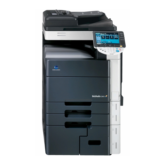
- Page 40 Theory of Operation Ver. 8.0 Jun. 2008 1. System configuration C451 1/2 System front view [12] [13] [14] [11] [10] A00KT1C203AB [17] [18] [17] [18] [15] [16] A00KT1C204AA [1] Main body [10] Output tray (for FS-519) OT-602 [2] Authentication unit: Biometric type AU-101 [11] Punch kit PK-510 [3] Authentication unit: IC card type...
- Page 41 1. System configuration Theory of Operation Ver. 8.0 Jun. 2008 2/2 System rear view [10] [11] A00HT1E001DB Main body Scan accelerator kit SA-501 Stamp unit SP-501 Fax multi line ML-501 Fax kit FK-502 Key counter kit KIT-1 Security kit SC-503 [10] i-Option LK-101*/102*/103...
-
Page 42: Product Specifications
Theory of Operation Ver. 8.0 Jun. 2008 2. Product specifications Product specifications A. Type Type Combination scanner and printer console type Copying system Electrostatic dry-powdered image transfer to plain paper Printing process Laser electrostatic printing system PC drum type OPC drum: KM-12 (OPC with high mold releasability) Scanning density 600 dpi Exposure lamp... - Page 43 2. Product specifications Theory of Operation Ver. 8.0 Jun. 2008 B. Functions Types of original Sheets, books, and three-dimensional objects Max. original size A3 or 11 x 17 Max. original weight Max. 2 kg Multiple copies 1 to 9999 Warm-up time When the sub power switch is turned ON at any timing while the main power (at ambient tempera- switch remains ON for a predetermined period of time or more...
- Page 44 Theory of Operation Ver. 8.0 Jun. 2008 2. Product specifications Fixed zoom ratios Full size x1.000 Metric area x0.500, x0.707, x0.816, x0.866 Reduction Inch area x0.500, x0.647, x0.733, x0.785 Metric area x1.154, x1.224, x1.414, x2.000 Enlargement Inch area x1.214, x1.294, x1.545, x2.000 Zoom ratios memory Metric area 3 memories...
- Page 45 2. Product specifications Theory of Operation Ver. 8.0 Jun. 2008 C. Paper Paper source (maximum tray capacity) Type Multiple Tray 1 Tray 2 Tray 3 Tray 4 bypass Plain paper ❍ ❍ ❍ ❍ ❍ (64 to 90 g/m / 17 (500 sheets) (500 sheets) (1500 sheets)
- Page 46 Theory of Operation Ver. 8.0 Jun. 2008 2. Product specifications *2: Image is not guaranteed when thick paper 3/4 is used. *3: Monochrome print only. *4: Paper to be reliably fed through only for C451 (127 to 210 g/m (33.75 to 55.75 lb)) Automatic duplex unit : Only the plain paper weighing 64 to 90 g/m (17 to 24 lb) or...
- Page 47 2. Product specifications Theory of Operation Ver. 8.0 Jun. 2008 E. Machine specifications • C650 Voltage: AC 100 V, 120 V, 127 V, 220-240 V Current: 100 V 15 A + 7A 110 V 15 A + 7A Power requirements 120 V 16 A 127 V...
- Page 48 Client Windows NT4.0 (SP6) Mac OS 9.2 or later/Mac OS X 10.2, 10.3, 10.4 Linux H. Scan functions Driver KONICA MINOLTA scanner driver Compatible operating Windows 2000, Windows XP/XP (incl. 64 bit) systems Monochrome: 75 pages/min C650: DF-610 Scan speed...
-
Page 49: Section Configuration
3. Section configuration Theory of Operation Ver. 8.0 Jun. 2008 Section configuration Auto document feed section * Standard C650: DF-610 C550/C451: DF-611 Scanner section (IR section) Fusing section Toner supply section Duplex section Transfer corona section (standard) Imaging unit section Bypass section (IU section) Write section (PH section) -
Page 50: Paper Path
Theory of Operation Ver. 8.0 Jun. 2008 4. Paper path Paper path C650/C550 A00JT1C201AA... - Page 51 4. Paper path Theory of Operation Ver. 8.0 Jun. 2008 C451 A00KT1C202AA...
-
Page 52: Image Creation Process
Theory of Operation Ver. 8.0 Jun. 2008 5. Image creation process Image creation process [11] Transfer belt cleaning [1] Photoelectric conversion [10] Paper [8] 1st image transfer separation [2] IR image pro- [9] 2nd image cessing transfer [3] Printer image processing [4] PC drum (K) [4] PC drum... - Page 53 5. Image creation process Theory of Operation Ver. 8.0 Jun. 2008 • A DC positive voltage is applied to the backside of the paper, thereby 2nd image transfer allowing the visible, developed image on the surface of the transfer belt to be transferred onto the paper. •...
-
Page 54: Composition/Operation
Theory of Operation Ver. 8.0 Jun. 2008 6. Overall composition Composition/Operation Overall composition Control block diagram Original glass moving motor (M202) Exposure lamp (FL201) Original glass position control Inverter board (INVB) Automatic boar (OGPCB) document feeder (DF-610, DF-611) CCD board (CCDB) Scaner elay board (REYB/SCAN) as standard Image processing... -
Page 55: Scanner Section (Ir Section)
7. Scanner section (IR section) Theory of Operation Ver. 8.0 Jun. 2008 Scanner section (IR section) Composition A00JT2C001AA A00JT2C028AA Original glass moving motor (M202) Glass moving unit Optical cooling fan motor (FM201) Scanner motor (M201) 20 degree sensor (PS202) Original size detection 2 sensor (PS205) Original size detection 1 sensor (PS204) -
Page 56: Ccd Unit
Theory of Operation Ver. 8.0 Jun. 2008 7. Scanner section (IR section) 7.1.1 CCD unit Scanning direction CCD sensor 37.3 µm 37.3 µm Main scanning direction 9.325 µm 9.325 µm 4036ma2602c0 Drive Scanner motor (M201) Scanner drive cable/R Exposure unit Mirror unit Glass moving unit Original glass moving... -
Page 57: Operation
7. Scanner section (IR section) Theory of Operation Ver. 8.0 Jun. 2008 Operation 7.3.1 Scan and exposure lamp control A. When the power is ON 1. The exposure unit moves from the scanner standby position to the home position. 2. Exposure unit moves from the home position to the shading position (under the shading correction sheet) and stops (in scanning direction). - Page 58 Theory of Operation Ver. 8.0 Jun. 2008 7. Scanner section (IR section) B. When the Start key is pressed (1) Original cover mode 1. Turning the Start key ON will turn the exposure lamp ON (at the standby position) 2. The exposure unit moves in the return direction and stops at the shading position. At the shading position, the gain adjustment is made.
- Page 59 7. Scanner section (IR section) Theory of Operation Ver. 8.0 Jun. 2008 (2) DF mode • The original fed by the document feeder will be read at the original DF glass for. The Exposure unit will move to the reading position and stops. The document will be read as the paper is transferred.
-
Page 60: Preventing Stain On The Df Original Glass
Theory of Operation Ver. 8.0 Jun. 2008 7. Scanner section (IR section) 7.3.2 Preventing stain on the DF original glass A. DF original glass movement • The reading lines will occur when DF original glass has stain. Shift mechanism for the DF original glass is provided to avoid this trouble. - Page 61 7. Scanner section (IR section) Theory of Operation Ver. 8.0 Jun. 2008 (2) DF original glass cleaning movement performed each time after reading a sheet of original • While reading multiple originals consecutively, the DF original glass moves widely back and forth between each original reading.
- Page 62 Theory of Operation Ver. 8.0 Jun. 2008 7. Scanner section (IR section) C. DF original glass movement in each mode (1) Normal mode Repeats the normal movement each time after reading a sheet of original Makes the DF original glass cleaning movement after completing a job NOTE This cleaning operation is not performed when the setting is made in the service mode as follows.
-
Page 63: Original Size Detection Control
7. Scanner section (IR section) Theory of Operation Ver. 8.0 Jun. 2008 7.3.3 Original size detection control A. Detection method • For detection of the original size, the reflective size sensors detect the length of the orig- inal while the CCD detects the width of the original. •... - Page 64 Theory of Operation Ver. 8.0 Jun. 2008 7. Scanner section (IR section) Metric area & china areas Table 1 Original CCD width (mm) size detection ~153.0 ~187.0 ~200.0 ~215.0 ~225.0 ~261.5 ~275.0 278.1~ sensor 1 16KS Table 2 Original size detection CCD width (mm) sensor...
- Page 65 7. Scanner section (IR section) Theory of Operation Ver. 8.0 Jun. 2008 B. Detection timing Validates the original length Validates the original size Original size sensors 1 (PS203), and 2 (PS204) 20 degree sensor (PS202) Exposure lamp (FL201) Original cover/DF open sensor (RS201) A00JT2E511DA...
-
Page 66: Write Section (Ph Section)
Theory of Operation Ver. 8.0 Jun. 2008 8. Write section (PH section) Write section (PH section) Composition PH unit A00JT2C005AA A00JT2C030AA Index mirror Index board (INDEXB) Index lens G3 lens Return mirror (light source) Synthetic mirror (Y,C,M) Laser drive board/C (LDDB/C) Laser drive board/M... -
Page 67: Operation
8. Write section (PH section) Theory of Operation Ver. 8.0 Jun. 2008 Operation 8.2.1 Outline • The surface of the photo conductor is irradiated with a laser light and an electrostatic latent image is thereby formed. • The PH unit has a single-piece construction. The PH unit has four semiconductor lasers with one laser for each four different color. -
Page 68: Laser Exposure Process
Theory of Operation Ver. 8.0 Jun. 2008 8. Write section (PH section) 8.2.2 Laser exposure process A. Operation 1. The K laser light enters the cylindrical lens via the return mirror (light source). The Y, M, and C laser light enter the cylindrical lens via the synthetic mirror and return mirror (light source). -
Page 69: Laser Emission Timing
8. Write section (PH section) Theory of Operation Ver. 8.0 Jun. 2008 8.2.3 Laser emission timing • After a print cycle has been started, when the stable rotation signals of PC drum and polygon motor are detected, a laser ON signal is output from the printer control board. •... -
Page 70: Laser Emission Area
Theory of Operation Ver. 8.0 Jun. 2008 8. Write section (PH section) 8.2.4 Laser emission area A. Main scanning direction • The print start position in the CD direction is determined by the CD print start signal (/ HSYNC) that is output from the printer control board and the width of the paper. •... -
Page 71: Color Registration Control (Color Shift Correction) System
8. Write section (PH section) Theory of Operation Ver. 8.0 Jun. 2008 8.2.5 Color registration control (color shift correction) system • In a tandem engine, each four different color has an independent image reproduction process. Color shift may occur because of variations in part accuracy. The color registra- tion control system automatically detects color shift and correct color shift in the main and sub scanning directions. - Page 72 Theory of Operation Ver. 8.0 Jun. 2008 8. Write section (PH section) A. Color shift correction method • Black (K) is used as a standard of reference when other colors, yellow (Y), magenta (M), and cyan (C), are individually corrected. (1) Color shift in the main scanning direction •...
-
Page 73: Color Skew Correction Control
8. Write section (PH section) Theory of Operation Ver. 8.0 Jun. 2008 8.2.6 Color skew correction control • Temperature may change inside the PH unit and the components can change over time. This may cause color skew problems. To prevent the problems, individual G3 lenses that correspond to Y, M, and C respectively have a color skew auto adjustment mechanism. -
Page 74: Ph Unit Temperature Detection Control
Theory of Operation Ver. 8.0 Jun. 2008 8. Write section (PH section) 8.2.7 PH unit temperature detection control • Temperature change inside the PH unit may cause color shift. To prevent the problem, temperature inside the PH unit is measured by the PH thermistor. The color registration control and the color skew control start to operate when the machine detects a certain amount of temperature change between the current temperature and the one measured when the color registration was performed last time. -
Page 75: Imaging Unit
9. Imaging unit Theory of Operation Ver. 8.0 Jun. 2008 Imaging unit Composition Imaging unit/K A00JT2C032AA A00JT2C007AA Imaging unit/Y, M, C A00JT2C031AA Developing unit/K Developing unit/Y, M, C Cleaning blade Toner collecting screw Cleaning blade PC drum PC drum Toner collecting screw A00JT2C013DA A00JT2C014DA PC drum charge corona... -
Page 76: Drive
Theory of Operation Ver. 8.0 Jun. 2008 9. Imaging unit Drive K PC drum motor (M18) K developing motor (M19) Color PC drum motor (M16) Color developing motor (M17) A00JT2C537DA... -
Page 77: Operation
9. Imaging unit Theory of Operation Ver. 8.0 Jun. 2008 Operation 9.3.1 IU life control • Each IU has EEPROM board that detects a new IU and keeps track of the service life of the IU. A. New IU detection •... - Page 78 Theory of Operation Ver. 8.0 Jun. 2008 9. Imaging unit B. When life is reached • The IU life counter is used to keep track of IU life. • When the life value is reached, a warning message is given on the screen. When a pre- determined number of printed pages are produced after the life value has been reached, the machine inhibits the initiation of a new print cycle with a message prompting the user to replace the IU given on the screen.
-
Page 79: 10. Photo Conductor Section
10. Photo conductor section Theory of Operation Ver. 8.0 Jun. 2008 10. Photo conductor section 10.1 Composition Charge generating layer Charge transport layer Aluminum cylinder 4036ma2338c0 PC drum A00JT2C033AA 10.2 Drive K PC drum motor (M18) Color PC drum motor(M16) PC drum/K PC drum/C PC drum/Y... -
Page 80: 10.3 Operation
Theory of Operation Ver. 8.0 Jun. 2008 10. Photo conductor section 10.3 Operation 10.3.1 PC drum drive mechanism • Two independent PC drum motors (for color and monochrome) are used for the drive mechanism to suppress incorrect color registration and uneven pitch. •... -
Page 81: K Pc Drum Phase Control
10. Photo conductor section Theory of Operation Ver. 8.0 Jun. 2008 10.3.2 K PC drum phase control • The K PC drum drive gear has a diameter larger than that of the color PC drum drive gears to enable the high-speed monochrome printing. •... -
Page 82: Pc Drum Small Amount Rotation Control
Theory of Operation Ver. 8.0 Jun. 2008 10. Photo conductor section 10.3.3 PC drum small amount rotation control • Humidity around the IU can produce a difference in sensitivity among different PC drums. This could lead to drum memory, allowing black bands to occur in the image. In addition, ozone stagnant in areas near the PC drum charge corona reduces sensitivity of the PC drums, causing white bands to occur in the image. -
Page 83: 11. Charge Corona Section
11. Charge Corona section Theory of Operation Ver. 8.0 Jun. 2008 11. Charge Corona section Corona wire 4038T2C027AA Grid mesh A00JT2C007AA IU/K IU/Y,M,C PC drum charge PC drum charge corona corona Corona Wire Cleaning Lever A00JT2C019DA A00JT2C018DA Cleaning blade Corona wire A00JT2C013DA A00JT2C014DA... -
Page 84: 11.1 Operation
Theory of Operation Ver. 8.0 Jun. 2008 11. Charge Corona section 11.1 Operation 11.1.1 PC drum charge corona ON/OFF control • The grid voltage (Vg) applied to the grid mesh is controlled through the image stabiliza- tion control. K PC drum motor (M18) Color PC drum motor (M16) Drum charge corona bias/ Y,M,C... - Page 85 11. Charge Corona section Theory of Operation Ver. 8.0 Jun. 2008 A. Operation timing • When the count goes over 2700 during a print job, the cleaning operation starts after the completion of the print job. However, when the remaining number of pages of the job is 50 or more, the job is stopped and the cleaning operation is performed.
-
Page 86: Cleaning/Main Erase Mechanism
Theory of Operation Ver. 8.0 Jun. 2008 11. Charge Corona section 11.1.3 Cleaning/main erase mechanism A. Main erase lamp/K control • IU/K has a main erase lamp/K located on the upstream side of the cleaning blade to improve cleaning performance. •... - Page 87 11. Charge Corona section Theory of Operation Ver. 8.0 Jun. 2008 B. Main erase lamp/Y,M,C control • The main erase lamp/Y, M, C radiation onto the PC drum surface neutralizes potential left on the surface of the PC drum. < IU/Y,M,C > Toner collecting screw Cleaning blade...
-
Page 88: 12. Developing Section
Theory of Operation Ver. 8.0 Jun. 2008 12. Developing section 12. Developing section 12.1 Composition < K developing unit> Developing roller Doctor blade A00JT2C007AA A00JT2C020DA Supply/agitating/ < Color developing unit > conveying screws Doctor blade Developing roller Supply/agitating/ conveying screws 4037T2C513AA K PC drum motor (M18) K developing motor (M19) -
Page 89: 12.2 Drive
12. Developing section Theory of Operation Ver. 8.0 Jun. 2008 12.2 Drive K PC drum motor (M18) K developing motor (M19) Color PC drum motor (M16) PC drum/K Developing roller Color developing motor (M17) PC drum/Y Supply/agitating/ A00JT2C021DA conveying screws... -
Page 90: 12.3 Operation
Theory of Operation Ver. 8.0 Jun. 2008 12. Developing section 12.3 Operation 12.3.1 Developing drive control Print request received LD enable (Y/M/C) LD enable (K) 1st image transfer pressure retraction motor (M21) 2nd image transfer pressure retraction motor (M3) Color PC drum motor (M16) K PC drum motor (M18) Color developing motor (M17) K developing motor (M19) -
Page 91: Developer Flow
12. Developing section Theory of Operation Ver. 8.0 Jun. 2008 12.3.2 Developer flow A. IU/K 1. Toner supplied from the front end of the Developing Unit is fed to the lower screw. It is then fed to the rear of the unit, while being mixed with developer and electrically charged by the Supply/Agitating/Conveying Screws. - Page 92 Theory of Operation Ver. 8.0 Jun. 2008 12. Developing section B. IU/Y,M,C 1. Toner supplied from the front end of the Developing Unit is fed to the lower screw. It is then fed to the rear of the unit, while being mixed with developer and electrically charged by the Supply/Agitating/Conveying Screws.
-
Page 93: Developing Bias
12. Developing section Theory of Operation Ver. 8.0 Jun. 2008 12.3.3 Developing bias • The developing bias voltage (Vdc) is applied to the developing roller so that an adequate amount of toner is attracted onto the surface of the PC drum. •... -
Page 94: Hmt (High Grade Micro Toning) Development
Theory of Operation Ver. 8.0 Jun. 2008 12. Developing section 12.3.4 HMT (high grade micro toning) development • The machine employs the two-component non-contact development system. • With the HMT method, the magnetic developer brush does not rub against the surface of the PC drum (the images). -
Page 95: Developer Scattering Preventive Mechanism
12. Developing section Theory of Operation Ver. 8.0 Jun. 2008 12.3.5 Developer Scattering Preventive Mechanism • To prevent the image and the machine interior from being dirtied, the color toner suction fan motor and K toner suction fan motor are incorporated to trap toner particles rising up inside the machine. - Page 96 Theory of Operation Ver. 8.0 Jun. 2008 12. Developing section B. IU/K • For IU/K, a black toner filter is installed under the IU and toner particles are trapped by the K toner suction fan motor during development. • As the K suction black toner filter and the IU unit come together as one piece, they are replaced together.
-
Page 97: Tcr Sensor Control
12. Developing section Theory of Operation Ver. 8.0 Jun. 2008 12.3.6 TCR sensor control • The TCR sensor is mounted on the underside of each of the developing sections. The sensor for C, M, Y and K is a magnetic type. Each of these sensors detects toner-to-car- rier ratio (T/C) of the developer. -
Page 98: 13. Toner Supply Section
Theory of Operation Ver. 8.0 Jun. 2008 13. Toner supply section 13. Toner supply section 13.1 Composition Toner cartridge/Y,M,C A00JT2C007AA Toner cartridge/K A00JT2C057AA Toner supply Toner supply Toner supply Toner supply drive section/C drive section/M drive section/K drive section/Y A00JT2C041AA A00JT2C056AA Conveyance screw /K Conveyance screw /Y, M, C... -
Page 99: 13.2 Drive
13. Toner supply section Theory of Operation Ver. 8.0 Jun. 2008 13.2 Drive Toner cartridge motor C/K (M14) Toner cartridge motor Y/M (M13) A00JT2C031DA... -
Page 100: 13.3 Operation
Theory of Operation Ver. 8.0 Jun. 2008 13. Toner supply section 13.3 Operation 13.3.1 Toner replenishing mechanism/control A. Overview • Toner replenishing mechanism consists of two toner supply steps. One replenishment step is from the toner cartridge to the sub hopper and the other is from the sub hopper to the developing unit. - Page 101 13. Toner supply section Theory of Operation Ver. 8.0 Jun. 2008 D. Control of toner replenishment to the sub hopper • Toner is supplied from the toner cartridge to the sub hopper based on the detection of the toner empty sensor. Conveyance screw Toner empty sensor/Y,M,C,K (PZS/C, PZS/M, PZS/Y, PZS/K)
- Page 102 Theory of Operation Ver. 8.0 Jun. 2008 13. Toner supply section F. Control of toner replenishment to the developing unit • Toner, which has been supplied from the toner cartridge to the sub hopper, is replen- ished to the developing unit by the toner supply motors that independently operate for Y, M, C, and K •...
-
Page 103: Toner Cartridge Life Control
13. Toner supply section Theory of Operation Ver. 8.0 Jun. 2008 13.3.2 Toner cartridge life control A. Toner cartridge detection/new unit detection timing • Individual cartridge detection is controlled by means of accessing the data of EEPROM board when the front upper door is closed or the power switch is turned ON. •... - Page 104 Theory of Operation Ver. 8.0 Jun. 2008 13. Toner supply section B. Toner cartridge empty control • After the toner cartridge empty condition is detected, if the sub hopper toner empty sen- sor continuously detects toner empty 10 times or more, the toner empty warning is dis- played.
-
Page 105: Shutter Mechanism
13. Toner supply section Theory of Operation Ver. 8.0 Jun. 2008 13.3.4 Shutter mechanism • To prevent toner from being spilled when the toner cartridge is removed from the machine, there is a shutter mechanism provided. When the toner cartridge is installed in the machine, the shutter opens. -
Page 106: 14. Transfer Corona Section
Theory of Operation Ver. 8.0 Jun. 2008 14. Transfer Corona section 14. Transfer Corona section 14.1 Composition 14.1.1 1st Image Transfer section A00JT2C045AA A00JT2C020AA 1st Image transfer roller/C 1st Image transfer roller/Y 1st Image transfer roller/M 1st Image transfer roller/K Cleaning brush Transfer belt drive roller A00JT2C036DA... -
Page 107: 2Nd Image Transfer Section
14. Transfer Corona section Theory of Operation Ver. 8.0 Jun. 2008 14.1.2 2nd Image Transfer section A00JT2C055AA A00JT2C046AA 2nd Image transfer roller A00JT2C027AA Temperature/humidity sensor A00JT2C050AA (TEM/HUMS) 2nd Image transfer roller Pressure welding alienation sensor (PS50) 2nd image transfer pressure retraction motor (M3) IDC registration sensor/R (IDCS/R) -
Page 108: 14.2 Drive
Theory of Operation Ver. 8.0 Jun. 2008 14. Transfer Corona section 14.2 Drive 14.2.1 1st Image Transfer Section Transfer belt motor (M1) Cleaner motor (M38) Transfer belt A00JT2C042DA 1st Image transfer roller/K 1st Image transfer roller/C 1st Image transfer roller/Y 1st image transfer pressure retraction motor (M21) - Page 109 14. Transfer Corona section Theory of Operation Ver. 8.0 Jun. 2008 14.2.2 2st Image Transfer Section 2nd Image transfer roller Pressure welding alienation sensor (PS50) 2nd image transfer pressure retraction motor (M3) IDC registration sensor/R (IDCS/R) Shutter Pressure lever IDC registration sensor/F (IDCS/F) A00JT2C043DA 14.3 Operation 14.3.1...
- Page 110 Theory of Operation Ver. 8.0 Jun. 2008 14. Transfer Corona section 14.3.2 1st Image Transfer Roller mechanism • The machine is provided with a mechanism that presses the 1st Image Transfer Rollers up against the inside of the Transfer Belt during the 1st image transfer stage. The 1st Image Transfer pressure retraction motor provides the drive for this operation.
- Page 111 14. Transfer Corona section Theory of Operation Ver. 8.0 Jun. 2008 B. Operation timing • The pressure operation starts when a print cycle starts and ends when the print cycle completes. Paper Moves Past 2nd Image transfer roller Start key ON Transfer belt motor (M1) 1st Image transfer pressure retraction motor (M21)
- Page 112 Theory of Operation Ver. 8.0 Jun. 2008 14. Transfer Corona section C. Pressure position changing mechanism • To extend the service life of the PC Drum/Y, M, C, the pressure position of the 1st Image Transfer Roller is changed between the monochrome mode and the color mode. In the monochrome mode, the 1st Image Transfer Roller/Y, M, C is left in the retracted position and the PC Drum/Y, M, C is stopped.
- Page 113 14. Transfer Corona section Theory of Operation Ver. 8.0 Jun. 2008 (2) Color mode • The pressure position of the Image Transfer Roller is where the PC Drum is in contact with the Transfer Belt for all four colors of toner. (3) Monochrome mode •...
- Page 114 Theory of Operation Ver. 8.0 Jun. 2008 14. Transfer Corona section D. Retraction mechanism • In addition to the change of the pressure position of the 1st image transfer roller, the machine moves the color retraction roller or the K retraction roller up and down to change the position of the image transfer on the surface of the transfer belt depending on the print mode of each job.
- Page 115 14. Transfer Corona section Theory of Operation Ver. 8.0 Jun. 2008 14.3.3 2nd image transfer roller pressure mechanism • The 2nd image transfer roller has the pressure/retraction mechanism which presses to and retracts from the transfer belt so the patterns made on the transfer belt except by printing (such as detection pattern during image stabilization) will not affect the 2nd image transfer roller.
- Page 116 Theory of Operation Ver. 8.0 Jun. 2008 14. Transfer Corona section B. Operation timing • The pressure operation starts when a print cycle starts and ends when the print cycle completes. Paper moves past 2nd Image transfer roller Start key ON Transfer belt motor (M1) 2nd Image transfer pressure retraction motor (M3)
- Page 117 14. Transfer Corona section Theory of Operation Ver. 8.0 Jun. 2008 14.3.4 IDC sensor shutter mechanism • The IDC sensor can be contaminated with toner since it is located under the transfer belt. There is a shutter mechanism provided for the sensor to prevent it from being contami- nated.
- Page 118 Theory of Operation Ver. 8.0 Jun. 2008 14. Transfer Corona section 14.3.5 ATVC (Auto transfer voltage control) • To adjust the 2nd image transfer output to the correct voltage, ATVC system is installed. A constant current is output to the 2nd image transfer roller to measure voltage. The measured voltage is corrected to be used for automatic adjustment of the 2nd image transfer output voltage.
- Page 119 14. Transfer Corona section Theory of Operation Ver. 8.0 Jun. 2008 14.3.6 Transfer belt cleaning • To scrape residual toner off the surface of the transfer belt, the transfer belt is provided with a cleaning brush and a charging brush. •...
- Page 120 Theory of Operation Ver. 8.0 Jun. 2008 14. Transfer Corona section 14.3.7 2nd image transfer roller cleaning • To remove residual toner off the surface of the 2nd Image transfer roller, a +/- DC bias is applied alternately to the roller, thereby moving the residual toner to the surface of the transfer belt.
- Page 121 14. Transfer Corona section Theory of Operation Ver. 8.0 Jun. 2008 14.3.8 Charge neutralization and separation of paper • To neutralize any charge potential left in the paper which has undergone the 2nd image transfer stage, a Charge Neutralizing Cloth is installed to the guide plate after the 2nd Image Transfer Roller.
- Page 122 Theory of Operation Ver. 8.0 Jun. 2008 14. Transfer Corona section 14.3.9 Detection of new transfer belt unit • When a new transfer belt unit is installed in the machine, the life counter is automatically cleared through new unit detection. •...
- Page 123 14. Transfer Corona section Theory of Operation Ver. 8.0 Jun. 2008 14.3.10 Pressure/retraction control during ACS mode • For monochrome printing in the ACS mode, the pressure/retraction operation of the 1st image transfer roller is controlled according to the number of monochrome originals that continue during multiple copies.
- Page 124 Theory of Operation Ver. 8.0 Jun. 2008 14. Transfer Corona section • ACS control operates only after the number of multi-copies for monochrome original is counted. “The pressure/retraction control for ACS mode” will not be properly executed with only one sheet of print job, since on the first copy, the control can be performed only for where the original is read and counted.
- Page 125 14. Transfer Corona section Theory of Operation Ver. 8.0 Jun. 2008 14.3.11 Electric discharge control before the 2nd image transfer • The small roller and the 2nd image transfer guide are installed under the drive roller to carry paper parallel to the transfer belt. This reduces electric discharge before the 2nd image transfer process and toner scattering when solid images are being printed.
-
Page 126: Toner Collecting Section
Theory of Operation Ver. 8.0 Jun. 2008 15. Toner collecting section 15. Toner collecting section 15.1 Composition A00JT2C048AA A00JT2C016AA Cleaning brush Transfer belt toner collecting screw Waste toner IU toner collecting screw A00JT2C054DA Agitating screw... - Page 127 15. Toner collecting section Theory of Operation Ver. 8.0 Jun. 2008 15.2 Drive Transfer belt motor (M1) Transfer belt toner collecting screw Cleaning brush Cleaner motor (M38) Toner collecting roller K PC drum motor (M18) Color PC drum motor (M16) Agitating screw Waste toner agitating motor (M20) A00JT2C055DA...
- Page 128 Theory of Operation Ver. 8.0 Jun. 2008 15. Toner collecting section 15.3 Operation 15.3.1 Toner collecting mechanism • Toner collected by the cleaning brush of the transfer belt and waste toner in each of the imaging units are conveyed by the corresponding toner collecting screws to the waste toner box.
- Page 129 15. Toner collecting section Theory of Operation Ver. 8.0 Jun. 2008 15.3.2 Waste toner agitation control • In order to avoid detecting an incorrect waste toner amount, the agitating coil is set in the waste toner box so that waste toner can build up evenly in the box. •...
- Page 130 Theory of Operation Ver. 8.0 Jun. 2008 15. Toner collecting section 15.3.4 Waste Toner Near-Full/Full detection control A. Waste toner near-full detection control • An optical sensor is used to detect waste toner. When the sensor is blocked for a given period of time, the machine determines that the Waste Toner box is nearly full of waste toner.
- Page 131 15. Toner collecting section Theory of Operation Ver. 8.0 Jun. 2008 • After the waste toner box has been replaced and the waste toner full sensor has been unblocked for a given period of time, the machine cancels the copying-disabled condi- tion, while at the same time automatically clearing the counter exclusive for the waste toner.
- Page 132 Theory of Operation Ver. 8.0 Jun. 2008 16. Paper feed section 16. Paper feed section 16.1 Composition 16.1.1 Tray1, 2 • Tray1 and 2 are same sensor position. A00JT2C277AA A00JT2C202AA Tray1 upper limit sensor (PS6) Tray1 vertical transport sensor (PS4) Tray1 paper feed sensor (PS5) Tray1 near empty sensor (PS3) Tray1 device detection sensor (PS1)
- Page 133 16. Paper feed section Theory of Operation Ver. 8.0 Jun. 2008 16.1.2 Tray3 Horizontal transport section (upper section) A00JT2C273AA A00JT2C204AA Tray3 paper feed section Tray3 upper limit sensor (PS20) Tray3 paper empty sensor (PS19) Tray3 paper feed sensor (PS21) Tray3 near empty sensor (PS22) A00JT2C300AA...
- Page 134 Theory of Operation Ver. 8.0 Jun. 2008 16. Paper feed section 16.1.3 Tray4 A00JT2C276AA A00JT2C205AA Tray4 upper limit sensor (PS25) Tray4 paper empty sensor (PS24) Tray4 near empty sensor (PS27) Tray4 paper feed sensor (PS26) A00JT2C294AA...
- Page 135 16. Paper feed section Theory of Operation Ver. 8.0 Jun. 2008 16.2 Drive 16.2.1 Tray1, 2 • Take-up motor drives the tray1 and 2 paper feed rollers. • Each paper feed roller has a clutch that is turned ON when it needs to be driven. Tray1 vertical transport motor (M5) Take-up motor (M22) Tray 1 paper feed clutch (CL1)
- Page 136 Theory of Operation Ver. 8.0 Jun. 2008 16. Paper feed section 16.2.2 Tray3 Tray3 transport clutch (CL6) Transport motor (M25) Tray3 paper feed clutch (CL5) Tray3 paper feed roller Transport roller Coupling A00JT2C301AA Tray3 lift-up motor (M23) Tray 16.2.3 Tray3 horizontal transport Vertical transport motor (M26) Horizontal transport clutch 2 (CL4) Horizontal transport clutch 1 (CL3)
- Page 137 16. Paper feed section Theory of Operation Ver. 8.0 Jun. 2008 16.2.4 Tray4 Tray4 paper feed clutch (CL7) Vertical transport motor (M26) Tray4 paper transport roller Transport motor (M25) Tray4 paper feed roller Coupling Tray4 lift-up motor (M24) A00JT2C295AA Tray Tray4 take-up axis...
- Page 138 Theory of Operation Ver. 8.0 Jun. 2008 16. Paper feed section 16.3 Operation 16.3.1 Tray1, 2 • Tray1 and Tray2 are controlled in the same control procedure. • Paper transport speed from Tray1 and Tray2 is the same as the system speed. A.
- Page 139 16. Paper feed section Theory of Operation Ver. 8.0 Jun. 2008 B. Paper feed speed reduction control • When paper reaches the tray1 (tray2) paper feed sensor, if the interval between the paper and the preceding paper is short, the take-up motor speed is reduced temporarily to adjust the paper interval to the proper one.
- Page 140 Theory of Operation Ver. 8.0 Jun. 2008 16. Paper feed section D. Paper supply level • The amount of remaining paper is indicated by the LED on the right side of each tray and by the screen of the control panel. •...
- Page 141 16. Paper feed section Theory of Operation Ver. 8.0 Jun. 2008 F. Paper size detection control • Paper width/length are detected to determine the paper size from their combination. Metric area Paper size detect board/1 (PSDTB/1) Tray1 CD paper size Tray1 CD paper size Paper size detect board/2 (PSDTB/2) sensor/1 (PS7)
- Page 142 Theory of Operation Ver. 8.0 Jun. 2008 16. Paper feed section Paper size detect board/1 (PSDTB/1) Paper size detect board/2 (PSDTB/2) Guide A00JT2C313AA...
- Page 143 16. Paper feed section Theory of Operation Ver. 8.0 Jun. 2008 G. Tray lifting motion control (1) When tray is slid in • When the upper limit sensor is unblocked (OFF) with the tray being closed, lift-up motor will rotate to start lifting up the paper lifting plate. •...
- Page 144 Theory of Operation Ver. 8.0 Jun. 2008 16. Paper feed section 16.3.2 Tray3, 4 A. Paper Feed control (1) Tray3 • When the interval between the paper and the preceding paper both fed from the tray3 is short, the tray3 transport clutch is stopped to adjust the paper interval to the proper one. •...
- Page 145 16. Paper feed section Theory of Operation Ver. 8.0 Jun. 2008 (2) Tray4 • When paper reaches the intermediate roller, if the interval between the paper and the preceding paper is short, the vertical transport motor is stopped to adjust the paper inter- val to the proper one.
- Page 146 Theory of Operation Ver. 8.0 Jun. 2008 16. Paper feed section B. Display of paper supply level • The amount of remaining paper is indicated by the LED on the right side of each tray and by the screen of the control panel. •...
- Page 147 16. Paper feed section Theory of Operation Ver. 8.0 Jun. 2008 D. Paper near-empty/paper empty detection • Paper near empty is detected by the tray3 (tray4) near empty sensor (blocking). • Paper empty is detected by the tray3 (tray4) paper empty sensor (tray3: unblocking, tray4: blocking).
- Page 148 Theory of Operation Ver. 8.0 Jun. 2008 16. Paper feed section E. Tray lifting motion control (1) Tray lifting motion • The tray is hung with the wire connected to the front and the back. • The wire is winded by the rotation of the lift-up motor, which lifts up the tray. •...
- Page 149 16. Paper feed section Theory of Operation Ver. 8.0 Jun. 2008 (3) During a print cycle • When the amount of paper decreases as the machine continues printing, a tray will grad- ually go down making the upper limit sensor of tray3 unblocked or that of the tray4 blocked.
- Page 150 Theory of Operation Ver. 8.0 Jun. 2008 16. Paper feed section F. Paper size detection • Tray3 and 4 don’t have paper size detection function. • To set a different paper size, press keys as follows. Service mode → System setting 2 → LCC size setting •...
- Page 151 16. Paper feed section Theory of Operation Ver. 8.0 Jun. 2008 G. Dehumidification heater control • Tray3 and 4 come equipped with the dehumidification heater. • Power switch of the dehumidification heater locates the bottom of the back of the main body.
-
Page 152: Bypass Section
Theory of Operation Ver. 8.0 Jun. 2008 17. Bypass section 17. Bypass section 17.1 Composition Paper side plate A00JT2C274AA Bypass Tray A00JT2C206AA Bypass paper width detection resistor (VR) Bypass paper empty Bypass sub tray set sensor (PS34) sensor (PS37) Bypass paper feed roller Bypass tray separator roller... - Page 153 17. Bypass section Theory of Operation Ver. 8.0 Jun. 2008 17.2 Drive Bypass tray up down motor (M28) Bypass paper lower sensor (PS36) Bypass paper limit sensor (PS35) Paper lifting plate Bypass paper feed motor (M27) Bypass paper feed motor (M27) Bypass tray separator roller Bypass paper feed roller A00JT2C283AA...
- Page 154 Theory of Operation Ver. 8.0 Jun. 2008 17. Bypass section 17.3 Operation 17.3.1 Bypass paper take-up control • Bypass paper feed starts after the bypass tray up down motor lifts up paper to the take- up position. • Paper is fed with the bypass paper feed motor. •...
- Page 155 17. Bypass section Theory of Operation Ver. 8.0 Jun. 2008 17.3.3 Bypass paper lifting motion control A. Move to paper feeding position • When the bypass paper feeding starts, the bypass tray up down motor makes a normal rotation to move the paper lifting plate up to the paper feeding position. When the paper lifting plate is moved up, the bypass paper limit sensor turns ON to stops the bypass tray motor at the feeding position.
- Page 156 Theory of Operation Ver. 8.0 Jun. 2008 17. Bypass section 17.3.4 Paper size detection • The size of the paper is detected by the combination of ON or OFF positions of three multi FD size sensors and the bypass paper width detection resistor. •...
- Page 157 17. Bypass section Theory of Operation Ver. 8.0 Jun. 2008 Inch area Bypass paper width detection Multi FD size Multi FD size Multi FD size resistor Paper detection size sensor/1 sensor/2 sensor/3 Width (mm) 80 to less than 115 115 to 144 inclusive ×...
- Page 158 Theory of Operation Ver. 8.0 Jun. 2008 17. Bypass section 17.3.5 Bypass unit open/close mechanism • The bypass unit open/close function has been installed to enable easier access to the jam controller and the tray1 paper feed part. Bypass unit A00JT2C265AA Tray1 paper feed part Lock tab...
- Page 159 18. Timing roller section Theory of Operation Ver. 8.0 Jun. 2008 18. Timing roller section 18.1 Composition 2st image transfer roller A00JT2C272AA Timing roller A00JT2C207AA • Drive Timing roller Registration motor (M2) (broken line) A00JT2C308AA...
- Page 160 Theory of Operation Ver. 8.0 Jun. 2008 18. Timing roller section 18.2 Operation 18.2.1 Timing roller control • The paper will create a loop between the tray 1 vertical transport roller (or ADU transport roller 4) and the when the paper is being conveyed in order to correct the regist motor skew.
- Page 161 18. Timing roller section Theory of Operation Ver. 8.0 Jun. 2008 18.2.2 OHP detection • OHP detection sensor checks to prevent printing on the paper other than OHP. • OHP detection will be performed after paper made the loop at the timing roller. When the OHP detection shows the different result from the setting on the operation panel, printing will stop to display “Error.”...
- Page 162 Theory of Operation Ver. 8.0 Jun. 2008 18. Timing roller section 18.2.3 Speed control • It controls the timing the paper reaches to the timing roller sensor. A. Operation • The tray1 vertical transport roller, the tray2 vertical transport roller and the intermediate roller may speed up, slow down or stop temporarily during paper transportation in order to adjust the paper interval.
-
Page 163: Fusing Section
19. Fusing section Theory of Operation Ver. 8.0 Jun. 2008 19. Fusing section 19.1 Composition IH coil unit A00JT2C271AA Fusing unit A00JT2C208AA Fusing pressure roller Fusing unit (Periodically thermistor (TH4) replaced parts) Soaking roller thermistor/1 (TH5) IH coil unit Soaking roller thermistor/2 (TH6) Separator finger (Fixed at the main body side) Soaking roller thermostat (TS2) - Page 164 Theory of Operation Ver. 8.0 Jun. 2008 19. Fusing section (1) Configuration of the temperature detector element of fusing unit NC sensor (TEMS) Heating roller thermistor/1 (TH1) Heating roller thermostat (TS1) Heating roller thermistor/2 (TH2) < Heating roller > Heating roller thermistor/3 (TH3) Fusing pressure roller thermistor (TH4) <...
- Page 165 19. Fusing section Theory of Operation Ver. 8.0 Jun. 2008 19.2 Drive Fusing pressure retraction motor (M29) Fusing retraction position sensor (PS59) Fusing pressure roller Pressure home sensor (PS55) Fusing motor (M30) Front side A00JT2C299AA Fusing pressure roller...
- Page 166 Theory of Operation Ver. 8.0 Jun. 2008 19. Fusing section 19.3 Operation 19.3.1 Heating roller structure • The inside surface of the heating roller is formed with Ni layer. • Ni layer of the heating roller is the nonmagnetic conducting layer in which eddy current is generated with magnetic flux.
- Page 167 19. Fusing section Theory of Operation Ver. 8.0 Jun. 2008 C650 C550/C451 Demagnetization coil ON conditions Heating roller end temperature (Degrees centigrade) CD length (mm) 1st demagnetization coil 2nd demagnetization coil 1st demagnetization coil 250 degrees centigrade Around 150 degrees 200 degrees centigrade 265 or more or more...
- Page 168 Theory of Operation Ver. 8.0 Jun. 2008 19. Fusing section 19.3.3 Fusing roller drive control A. Fusing pressure roller rotating speed control • In order to avoid fusing error, the rotation speed of the fusing belt is exchanged according to the paper type or the print mode •...
- Page 169 19. Fusing section Theory of Operation Ver. 8.0 Jun. 2008 19.3.4 Fusing loop control A. Adjustment of the loop amount • By creating a paper loop, the speed difference between the fusing and paper convey- ance at 2nd transfer part will be adjusted. It prevents the double transferred image or brush effect.
- Page 170 Theory of Operation Ver. 8.0 Jun. 2008 19. Fusing section 19.3.5 Fusing pressure roller pressure/retraction mechanism • To ensure prolonged durability of the heating roller, the heating roller and fusing pressure roller is retracted * from the fusing belt during any time other than a print cycle. (The roller is, however, retracted * during a print cycle using envelopes.) *1: The fusing pressure roller does not completely retract but is slightly pressed to the...
- Page 171 19. Fusing section Theory of Operation Ver. 8.0 Jun. 2008 19.3.6 Fusing temperature control • The surface temperature of the heating roller and the fusing pressure roller are detected to control the amount of the heat of the IH heater and the fusing pressure roller heater lamp in the soaking roller in order to maintain the appropriate fusing temperature.
- Page 172 Theory of Operation Ver. 8.0 Jun. 2008 19. Fusing section A. Temperature adjustment control of IH heater • Temperature of the heating roller is controlled within the given range during warm-up, printing and standby. • Temperature of the heating roller is measured with the NC sensor, and the temperature change (up/down) is monitored by comparing the current temperature with the value of one second before.
- Page 173 19. Fusing section Theory of Operation Ver. 8.0 Jun. 2008 C. Temperature control during stand-by • The fusing temperature in the standby state is prevented from being dropped. • The temperature is controlled by each modes (low temperature, normal, high humidity), within predetermined time from standby control start.
- Page 174 Theory of Operation Ver. 8.0 Jun. 2008 19. Fusing section D. Temperature control during printing • Temperature is controlled to maintain the optimal fusing status when the temperature is getting down due to the paper type, the printing mode, the small size paper or paper passing, or due to warm-up with cooled fusing unit.
- Page 175 19. Fusing section Theory of Operation Ver. 8.0 Jun. 2008 (3) C451 only for Taiwan control temperature Fusing pressure Paper type Heating roller setting Soaking roller roller setting (Same control in monochrome temperature setting temperature temperature and color) (Degree centigrade) (Degree centigrade) (Degree centigrade) Plain paper (Duplex print)
- Page 176 Theory of Operation Ver. 8.0 Jun. 2008 19. Fusing section E. Fusing temperature control during printing. • Fusing temperature control prevents declining of the image stability as well as reduces curling of the paper, uneven waxing, offset, etc., according to the paper type to be used. •...
- Page 177 19. Fusing section Theory of Operation Ver. 8.0 Jun. 2008 19.3.7 Protection from abnormally high temperature • The machine provides protection against abnormally high temperature of the fusing unit in the following three steps. A. < Soft protection > • When the controlled temperature of each roller is detected higher than the predeter- mined value for more than 1 second, the temperature is judged to be abnormally high, and the trouble code appears.
- Page 178 Theory of Operation Ver. 8.0 Jun. 2008 19. Fusing section C. < Overheat protection > • If the abnormal high temperature of soft protection/hard protection cannot be detected due to thermistor trouble, thermostat blocks the power supply to each heater lamp. •...
- Page 179 19. Fusing section Theory of Operation Ver. 8.0 Jun. 2008 19.3.8 Sensor disconnection detection control • If the temperature of the NC sensor/thermistor fails to reach the specified temperature in the given period after the warm-up started, the sensor is judged to have disconnection, and the trouble code will appear.
- Page 180 Theory of Operation Ver. 8.0 Jun. 2008 19. Fusing section 19.3.11 PPM control • PPM (PCM) control is made to secure the paper space and reduce the number of print- ing per minutes so that the center temperature of the heating roller and pressure roller can be reduced, which prevents the edge temperature from going up.
- Page 181 19. Fusing section Theory of Operation Ver. 8.0 Jun. 2008 Judge- Measurement Corrected Criteria ment time rate Central temperature of the heating roller is lower than setting value by up to 15 degrees centigrade Central temperature of the fusing pressure roller is lower than setting value by over 35 degrees centi- grade Central temperature of the heating roller is lower...
- Page 182 Theory of Operation Ver. 8.0 Jun. 2008 20. Paper exit section 20. Paper exit section 20.1 Composition Switchback paper exit section A00JT2C280AA Paper exit section A00JT2C210AA Switchback roller Exhaust sensor (PS39) Paper exit roller/2 A00JT2C309AA Paper exit change gate Paper exit roller/1...
- Page 183 20. Paper exit section Theory of Operation Ver. 8.0 Jun. 2008 20.2 Drive • The exit and switch roller are driven by the exclusive motor. Switchback Motor (M33) Fusing drive motor (M4) Paper exit roller A00JT2C310AA Paper exit roller/2...
- Page 184 Theory of Operation Ver. 8.0 Jun. 2008 20. Paper exit section 20.3 Operation 20.3.1 Switchback control • When the fusing is completed on the first side of duplex print, switchback snap is switched down to transport the sheet to the switchback part. When the fusing is com- pleted on the sheet of single print or second side of duplex print, the sheet is transported to the exit section.
-
Page 185: Duplex Section
21. Duplex section Theory of Operation Ver. 8.0 Jun. 2008 21. Duplex section 21.1 Composition A00JT2C275AA A00JT2C211AA ADU transport sensor/1 (PS47) ADU door sensor (PS49) ADU transport sensor/2 (PS48) A00JT2C291AA... - Page 186 Theory of Operation Ver. 8.0 Jun. 2008 21. Duplex section 21.2 Drive 21.2.1 Duplex unit drive ADU transport roller/1 ADU transport motor/1 ADU transport roller/2 (M31) ADU transport roller/3 ADU transport motor/2 (M32) ADU transport roller/4 A00JT2C291AA...
- Page 187 21. Duplex section Theory of Operation Ver. 8.0 Jun. 2008 21.3 Operation 21.3.1 Duplex unit transport control • The paper transported to the switchback part stops at the stop position 1 and then the switchback roller turns around to transport the sheet to the duplex unit. •...
- Page 188 Theory of Operation Ver. 8.0 Jun. 2008 21. Duplex section 21.3.2 Duplex print • Duplex print changes its control method according to the paper length. Paper size Duplex print method Lower limit Upper limit Less than 217 mm Three alternative paper feed 217 mm or more Less than 433 mm Two alternative paper feed...
- Page 189 21. Duplex section Theory of Operation Ver. 8.0 Jun. 2008 Operation 4 • The image of the first page is printed on the paper re-sup- plied from the duplex section. A00JT2C239AA Operation 5 • Exhaust the first sheet of the paper. •...
- Page 190 Theory of Operation Ver. 8.0 Jun. 2008 21. Duplex section B. 2 sheets alternate supply Operation 1 • The first sheet of paper is supplied and the image of the second page is printed. A00JT2C236AA Operation 2 • First sheet of the paper is turned around at the switchback part and transported to the duplex part.
- Page 191 21. Duplex section Theory of Operation Ver. 8.0 Jun. 2008 Operation 5 • Exhaust the first sheet of paper. • At the same time, the image of the sixth page is printed on the third sheet of paper. • The second sheet of the paper stands by at the stop posi- tion 3 until the paper pitch for third sheet is assured.
- Page 192 Theory of Operation Ver. 8.0 Jun. 2008 21. Duplex section C. 3 sheets alternate supply Operation 1 • The first sheet of paper is supplied and the image of the second page is printed. A00JT2C236AA Operation 2 • The first sheet of paper is turned around at the switchback and transported to the duplex part.
- Page 193 21. Duplex section Theory of Operation Ver. 8.0 Jun. 2008 Operation 5 • First sheet of the paper is re-supplied and an image of the first page is printed on, then it is transported to the paper exist part. • At the same time, the second sheet of the paper is trans- ported to the stop position 3.
-
Page 194: Image Stabilization Control
Theory of Operation Ver. 8.0 Jun. 2008 22. Image stabilization control 22. Image stabilization control 22.1 Overview • The machine provides the following image stabilization control to ensure stabilized copy image. Purpose Control Control means • IDC registration sensor adjust- ment control •... - Page 195 22. Image stabilization control Theory of Operation Ver. 8.0 Jun. 2008 22.2 Operation 22.2.1 IDC registration sensor adjustment control • Controls changes in characteristics due to change with time and contamination of the transfer belt and IDC registration sensor, part-to-part variations in the sensors, and change of environment.
-
Page 196: Operation Sequence
Theory of Operation Ver. 8.0 Jun. 2008 22. Image stabilization control 22.3 Operation sequence Sequence Mode 1 Mode 2 Mode 3 Mode 4 Mode 5 IDC registration IDC registration IDC registration sensor adjust- sensor adjust- Registration Registration sensor adjust- ment ment ment Dmax density... -
Page 197: Operation Timing
22. Image stabilization control Theory of Operation Ver. 8.0 Jun. 2008 22.4 Operation timing A. Image stabilization when not printing Mode Operation condition • A new transfer belt is detected • IU units are removed and installed. • A new IU is detected (Image stabilization sequence is executed only for a new IU that Mode 1 has been installed) •... - Page 198 Theory of Operation Ver. 8.0 Jun. 2008 22. Image stabilization control B. Image stabilization during printing Mode Operation condition Operation timing • Temperature change inside the machine is detected. (The machine detects absolute humidity that reaches the threshold temperature change for the first time since •...
- Page 199 22. Image stabilization control Theory of Operation Ver. 8.0 Jun. 2008 C. Basic image stabilization operation flow Make a check for each print signal Is there a change in print conditions? Does the count of the pages reach the predetermined count? Is there a PH temperature...
- Page 200 Theory of Operation Ver. 8.0 Jun. 2008 22. Image stabilization control D. Image stabilization execution flow based on a count while a print cycle is pro- gressing A print job is being processed Does the count of the pages reach the predetermined count? Is there a...
-
Page 201: Image Processing
23. Image processing Theory of Operation Ver. 8.0 Jun. 2008 23. Image processing 23.1 Scanner section image processing block diagram 1. Photoelectric conversion CCD sensor board 2. Analog-to-digital conversion Image processing board 3. Shading correction 4. Line-to-line variation correction/color aberration correction To the MFP board •... -
Page 202: Write Section Image Processing Block Diagram
Theory of Operation Ver. 8.0 Jun. 2008 23. Image processing 23.2 Write section image processing block diagram From scanner section MFP board 1. Resolution conversion processing in the main scanning direction/ movement processing 2. Resolution conversion processing in the sub scanning direction 3. - Page 203 23. Image processing Theory of Operation Ver. 8.0 Jun. 2008 • The following detail the image processing operations performed by MFP board on the Write section. 1. FIFO memory is used to enlarge or reduce images in the main scanning direction. The image is enlarged by increasing the number of data readings and reduced by decreasing the number of data readings.
- Page 204 Theory of Operation Ver. 8.0 Jun. 2008 23. Image processing 20. When copying in a photo mode or making PC print, the R, G, and B data is con- verted to the Y, M, C, and K density data. Also, the masking processing, which compensates for the deviation in the spectral reflection characteristics of the toner, and UCR/BP processing are performed on the image data.
-
Page 205: Other Control
24. Other control Theory of Operation Ver. 8.0 Jun. 2008 24. Other control 24.1 Fan control 24.1.1 Construction Optical cooling fan motor (FM201) Rear side cooling fan motor (FM16) K toner suction fan motor (FM8) MFP control board cooling fan motor (FM17) Color toner suction fan motor (FM7) Fusing cooling fan motor/1 (FM2) - Page 206 Theory of Operation Ver. 8.0 Jun. 2008 24. Other control 24.1.2 Operation A. Function Motor name Control conditions • Paper will be sucked between transfer part and fusing part, so it will have a stable behavior and go smoothly into the fusing roller. Suction fan motor (FM1) The air inside will be exhausted outside the unit.
- Page 207 24. Other control Theory of Operation Ver. 8.0 Jun. 2008 Motor name Control conditions Exit cooling fan motor/1, / • In order to avoid toner attachment while the exit plate kit is used, outside 2, /3 (FM101, FM102, air is applied to the paper to cool it. FM103) •...
- Page 208 Theory of Operation Ver. 8.0 Jun. 2008 24. Other control Motor name Control Control conditions (outline) • Plug-in/sub-power switch OFF Stop • In sleep • When updating the firmware • In standby, low power Ozone ventilation fan • At paper-jam, in trouble, or when the door is open Half speed motor (FM6) •...
- Page 209 24. Other control Theory of Operation Ver. 8.0 Jun. 2008 Motor name Control Control conditions (outline) • Plug-in/sub-power switch OFF • In low-power or sleep • When updating the firmware Stop IH cooling fan motor/2 • At paper-jam, in trouble, or when the door is open (FM11) •...
- Page 210 Theory of Operation Ver. 8.0 Jun. 2008 24. Other control Motor name Control Control conditions (outline) • Plug-in/sub-power switch OFF • In low-power or sleep • When updating the firmware Stop • At paper-jam, in trouble, or when the door is open •...
-
Page 211: Counter Control
24. Other control Theory of Operation Ver. 8.0 Jun. 2008 24.2 Counter control 24.2.1 Construction Printer control board Slide Interface board Total counter (PRCB) (REYB/SL) Key counter (option) MFP board (MFPB) Electronic counter A00JT2C257AA Name Function/system • Displays the cumulative number of copies and prints of all jobs. Total counter •... -
Page 212: Power Supply Unit
Theory of Operation Ver. 8.0 Jun. 2008 24. Other control 24.3 Power supply unit A. C650/C550/C451 • The main body uses a single outlet. Power supply A00HT2C305AA B. C650 (Only Taiwan) • The main body uses two outlets (15 A + 7 A) to achieve an even higher printing speed and a shorter warm-up time. - Page 213 24. Other control Theory of Operation Ver. 8.0 Jun. 2008 24.4 Parts operated when the main power switch and sub power switch are turned ON 24.4.1 Parts operated when the main power switch and sub power switch are turned ON •...
-
Page 214: Authentication Unit (Biometric Type) (Au)
Theory of Operation Ver. 8.0 Jun. 2008 24. Other control 24.5 Authentication unit (Biometric type) (AU-101) • A finger vein pattern is used for personal identification. • Vein patterns are inside the body and cannot be visually recognized. This makes vein patterns extremely difficult to forge or falsify. - Page 215 24. Other control Theory of Operation Ver. 8.0 Jun. 2008 Blank Page...
- Page 216 SERVICE MANUAL THEORY OF OPERATION 2007.05 Ver. 2.0...
- Page 217 Revision history After publication of this service manual, the parts and mechanism may be subject to change for improvement of their performance. Therefore, the descriptions given in this service manual may not coincide with the actual machine. When any change has been made to the descriptions in the service manual, a revised version will be issued with a revision mark added as required.
- Page 218 Theory of Operation Ver. 2.0 May 2007 CONTENTS DF-611/610 Outline Product specifications ..................... 1 Section configuration....................5 Paper path....................... 5 Composition/Operation Composition ......................7 Drive ........................8 Operation ........................ 9 Document feed tray ascent/descent mechanism ..........9 6.1.1 Document feed tray ascent ................9 6.1.2 Document feed tray descent .................
- Page 219 Theory of Operation Ver. 2.0 May 2007 Blank Page...
-
Page 220: Outline
Theory of Operation Ver. 2.0 May 2007 1. Product specifications Outline Product specifications A. Type Name Reverse automatic document feeder Paper feed section Paper feed from top of stack Image reading section Sheet-through system Type Turnover section Switchback system Exit section Straight exit system Installation Screw cramp to the main body... -
Page 221: Product Specifications
1. Product specifications Theory of Operation Ver. 2.0 May 2007 D. Paper feed prohibited originals • If fed, trouble occurrence will be highly possible. Type of original Possible trouble Paper feed failure, damaged sheet, defective drive Sheets stapled or clipped together mechanism due to jammed staples or clips Sheets glued together Paper feed failure, damaged sheet... - Page 222 Theory of Operation Ver. 2.0 May 2007 1. Product specifications F. Mixed original feed chart For metric Max. original 297 mm 257 mm 210 mm 182 mm 148 mm 128 mm size Mixed original size 297 mm 257 mm 210 mm 182 mm 148 mm 128 mm...
- Page 223 1. Product specifications Theory of Operation Ver. 2.0 May 2007 G. Machine specifications DC 24 V (supplied from the main unit) Power requirements DC 5 V (generated within the DF-611/DF-610) Max. power 60 W or less consumption 618 mm (W) x 575 mm (D) x 130 mm (H) Dimensions 24.25 inch (W) x 22.75 inch (D) x 5 inch (H) DF-611: 16.1 kg (35.5 lb)
-
Page 224: Section Configuration
Theory of Operation Ver. 2.0 May 2007 2. Section configuration Section configuration Transport section Paper feed section Paper exit section Turnover section Paper exit turnover section Paper path Feed tray Feed tray Document read position... - Page 225 3. Paper path Theory of Operation Ver. 2.0 May 2007 Blank Page...
-
Page 226: Composition/Operation
Theory of Operation Ver. 2.0 May 2007 4. Composition Composition/Operation Composition A01HT2C001AA A01HT2C002AA Transportation cover Document guide Document feed tray Original read section Hookup cord Magnet Turnover cover Feed roller Pick-up roller Registration roller Separation roller Switch back roller Exit roller Reading roller 2 Reading roller 1 Exit switch back roller... -
Page 227: Drive
5. Drive Theory of Operation Ver. 2.0 May 2007 Drive (1) C650 Exit motor (M3) Take-up motor (M2) Regist motor (M7) Reading motor (M1) (2) C550/C451 Exit motor (M3) Take-up motor (M2) Reading motor (M1) -
Page 228: Operation
Theory of Operation Ver. 2.0 May 2007 6. Operation Operation Document feed tray ascent/descent mechanism • The document feed tray will move up to feed the original. • Ascent/descent of the document feed tray will be performed by the lift-up motor. 6.1.1 Document feed tray ascent •... -
Page 229: Feeding The Original
6. Operation Theory of Operation Ver. 2.0 May 2007 Feeding the original 6.2.1 Feeding operation (1) C650 • The paper feed section consists of the pick-up roller, feed roller as well as the separation roller, and is directly driven by the take-up motor. •... -
Page 230: Transfer Mechanism
Theory of Operation Ver. 2.0 May 2007 6. Operation Transfer mechanism (1) C650 • The original transferred from the paper feed section will be transferred to the paper exit section or turnover section by the registration roller, the reading roller 1 and 2, and the switch back roller. -
Page 231: Transfer Mechanism For Turnover/Paper Exit
6. Operation Theory of Operation Ver. 2.0 May 2007 Transfer mechanism for turnover/paper exit (1) C650 • The original transferred from the transport section will switch back or exit by the exit roller, the switch back roller, and the exit switch back roller. •... -
Page 232: Switching Mechanism For Turnover/Paper Exit
Theory of Operation Ver. 2.0 May 2007 6. Operation Switching mechanism for turnover/paper exit 6.5.1 Turnover section • Pathway of the original will be switched and the original will turnover by the switch back lever. • Switch back lever is switched by ON/OFF of the switch back solenoid. When in 1-sided mode: When in 2-sided/ Switch back solenoid will be OFF... -
Page 233: Paper Path
7. Paper path Theory of Operation Ver. 2.0 May 2007 Paper path 1-sided mode (1) C650 1. Pressing the start key will lift up the feed tray and press the reading roller 1. 2. After the feed tray is lifted up, the feed motor is started and the pick-up roller and the feed roller will start rotating to start feeding the first sheet of paper. -
Page 234: 2-Sided Mode
Theory of Operation Ver. 2.0 May 2007 7. Paper path 2-sided mode 1. The fist side of the original will be read. 2. The original will be transferred to the turnover section (switch back solenoid will be 3. In order to read the second side of the original which is transferred to the turnover section, the switch back roller will reverse by the switch pack operation of the regist motor (C650) or take-up motor (C550/C451), and transfer the original to the take- up part. -
Page 235: Mixed Original/Ams Mode
7. Paper path Theory of Operation Ver. 2.0 May 2007 Mixed original/AMS mode • Paper path control will be the same as the 2-sided mode. 1. The original will be fed to detect the paper length. (It will not read the original) The length of the original will be judged by the before read sensor ON time, and the width of the original will be judged by the mixed sensor 1, 2, and 3. - Page 236 Theory of Operation Ver. 2.0 May 2007 7. Paper path 4. The original will be transferred to the paper exit turnover section after second side is read. (switch back solenoid will be ON) Exit switch back roller will reverse by the exit motor’s reverse operation. 5.
-
Page 237: Original Size Detection
8. Original size detection Theory of Operation Ver. 2.0 May 2007 Original size detection Length sensor 1 Length sensor 3 Length sensor 4 (PS10) (PS12) (PS13) Length sensor 2 (PS11) Before read sensor (PS9) Document width detection variable resistor (VR1) Mixed sensor 1 (PS19) Mixed sensor 3... -
Page 238: Detecting The Open/Close
Theory of Operation Ver. 2.0 May 2007 9. Detecting the open/close Detecting the open/close DF 20 degree open/close detection • The lever actuator is provided to detect the original size when using the auto document feeder as the original cover. •... -
Page 239: 10. Cooling Inside The Unit
10. Cooling inside the unit Theory of Operation Ver. 2.0 May 2007 10. Cooling inside the unit • The air will be blown inside the unit by the cooling fan in order to avoid the temperature increase of the driving motor and the board. Cooling fan motor (FM1) - Page 240 SERVICE MANUAL THEORY OF OPERATION 2007.05 Ver. 2.0...
- Page 241 Revision history After publication of this service manual, the parts and mechanism may be subject to change for improvement of their performance. Therefore, the descriptions given in this service manual may not coincide with the actual machine. When any change has been made to the descriptions in the service manual, a revised version will be issued with a revision mark added as required.
- Page 242 Theory of Operation Ver. 2.0 May 2007 CONTENTS LU-301 Outline Product specification ....................1 Section configuration....................2 Paper feed path ....................... 2 Composition/Operation Composition ......................3 Drive ........................4 Operations....................... 5 Paper Feed and Transport Control ............... 5 Paper level detection .................... 7 Paper empty detection..................
- Page 243 Theory of Operation Ver. 2.0 May 2007 Blank Page...
-
Page 244: Outline
Theory of Operation Ver. X.X XXX. 20XX 1. Product specification Outline Product specification A. Type Name 3,000 sheets Large Capacity Unit Type External option attached to the right side of the main body Document alignment Center B. Paper type Type Size Weight Capacity... -
Page 245: Section Configuration
2. Section configuration Theory of Operation Ver. 2.0 May 2007 Section configuration Paper transport section Paper storage section Paper feed section Dehumidification heater A03NT1C002AA Paper feed path Transportation to main body Paper feed from the tray A03NT1C001AA Main body LU-301... -
Page 246: Composition/Operation
Theory of Operation Ver. 2.0 May 2007 4. Composition Composition/Operation Composition A03NT2C204AA LU drive board (LUDB) Near empty sensor /1 (PS5) Near empty sensor /2 (PS6) LU door switch (MS1) Upper limit sensor (PS2) Tray LED (LED) Dehumidification heater A03NT2C213AA (DH) Lift-up motor (M1) Paper empty sensor (PS4) -
Page 247: Drive
5. Drive Theory of Operation Ver. 2.0 May 2007 Drive Feed roller Transport motor (M3) Paper feed motor (M2) Transport roller A03NT2C214AA... -
Page 248: Operations
Theory of Operation Ver. X.X XXX. 20XX 6. Operations Operations Paper Feed and Transport Control • A paper take-up and feed sequence starts if there are no preceding sheet of paper or if the leading edge of the preceding paper has moved past the tray 2 vertical transport roller. - Page 249 6. Operations Theory of Operation Ver. 2.0 May 2007 • Layout of sensors and rollers Paper feed sensor (PS3) Transfer roller Feed roller Tray2 vertical transport sensor (PS12) Tray2 vertical transport roller A03NT2C002AA Main body LU-301...
-
Page 250: Paper Level Detection
Theory of Operation Ver. 2.0 May 2007 6. Operations Paper level detection • The level of the paper still available for use is determined based on the outputs from near empty sensor/1 and sensor/2. • A near empty condition is detected when the amount of paper left still available for use is about 50 sheets ±... -
Page 251: Paper Empty Detection
6. Operations Theory of Operation Ver. 2.0 May 2007 Paper empty detection • The paper empty sensor detects a paper empty condition. Paper empty sensor (PS4) Upper limit sensor (PS2) Paper still available A03NT2C205AA Paper empty condition A03NT2C205AA Paper level indicator •... -
Page 252: Tray Lift-Up Control
Theory of Operation Ver. 2.0 May 2007 6. Operations Tray lift-up control 6.5.1 Tray ascend/descend mechanism • The tray is suspended by the wires at the front and rear. • Rotation of the lift-up motor winds the wires, which causes the tray to go up. •... - Page 253 6. Operations Theory of Operation Ver. 2.0 May 2007 A. Closing the LU door • The condition of the upper limit sensor signal is checked when the LU door is closed. If the upper limit sensor is unblocked, the lift-up motor is energized so that lifting of the tray is started.
-
Page 254: Paper Size Detection
Theory of Operation Ver. 2.0 May 2007 6. Operations 6.5.2 Paper size detection • The LCT is not capable of detecting the paper size. • The paper size is set by Service Mode → System 2 → LCT Paper Size Setting. A03NT2E500DA Dehumidification heater control •... - Page 255 6. Operations Theory of Operation Ver. 2.0 May 2007 Blank Page...
- Page 256 SERVICE MANUAL THEORY OF OPERATION 2008.05 Ver. 2.0...
- Page 257 Revision history After publication of this service manual, the parts and mechanism may be subject to change for improvement of their performance. Therefore, the descriptions given in this service manual may not coincide with the actual machine. When any change has been made to the descriptions in the service manual, a revised version will be issued with a revision mark added as required.
- Page 258 Theory of operation Ver. 2.0 May 2008 CONTENTS ZU-603 Outline Product specification ....................1 Section configuration....................6 Paper path....................... 7 Construction/Operation Conveyance section ....................9 Composition......................9 Drive ........................10 Operation ......................12 4.3.1 Conveyance path switching................. 12 4.3.2 Conveyance line speed switching ............... 14 4.3.3 Registration control ..................
- Page 259 Theory of operation Ver. 2.0 May 2008 Blank Page...
-
Page 260: Outline
Theory of operation Ver. 2.0 May 2008 1. Product specification Outline Product specification A. Type Type Z-folding multi punching device B. Functions Punch Punching method Reciprocal punching method (punching each paper) No. of holes Metric area : 2 holes/4 holes (switched automatically) Inch area : 2 holes/3 holes (switched automatically) Hole diameter... - Page 261 1. Product specification Theory of operation Ver. 2.0 May 2008 Z-folding Folding length A07TT1C010AA Paper size L (mm) a (mm) 209 or less 181 or less 4 ± 2 11 x 17 215 or less 8K *1 194 or less Folding precision 2 mm or less 2 mm or less...
- Page 262 Theory of operation Ver. 2.0 May 2008 1. Product specification Maximum tray capacity (80 g/m The maximum number of sheets for the FS main tray at the Z-folding operation • Z-folding continuous: Max. 30 sheets • Z-folding/stapling: See the table below No.
- Page 263 1. Product specification Theory of operation Ver. 2.0 May 2008 C. Type of paper No punch mode Same as the main body. Punch mode Paper size • Combination with the folding/saddle stitching mode is not available. Metric area 2holes: A3, B4, A4, A4S, B5, B5S, A5, A5S, 8K *1, 16K *1, 16KS *1, 8 x 13, 8- x 13, 8-...
- Page 264 Theory of operation Ver. 2.0 May 2008 1. Product specification D. Maintenance Maintenance Same as the main body. Machine service life Same as the main body. E. Machine specifications Power requirements 100 to 240 VAC (automatic switching) DC5 V (supplied from the main body) Max.
-
Page 265: Section Configuration
2. Section configuration Theory of operation Ver. 2.0 May 2008 Section configuration Conveyance section Z-folding section Punch section Punch scraps conveyance section Finisher ZU-603 Main body A07TT1C009AA... -
Page 266: Paper Path
Theory of operation Ver. 2.0 May 2008 3. Paper path Paper path A. Straight mode/punch mode (for the small size paper : A5, 5- x 8- A07TT1C005AA B. Punch mode (excluding the small size paper) A07TT1C007AA... - Page 267 3. Paper path Theory of operation Ver. 2.0 May 2008 C. Z-folding mode/punch + Z-folding mode From the main body to the 1st folding A07TT1C013AA From the 1st folding to the 2nd folding From the 2nd folding to the paper exit...
-
Page 268: Construction/Operation
Theory of operation Ver. 2.0 May 2008 4. Conveyance section Construction/Operation Conveyance section Composition Conveyance sensor (PS1) Gate solenoid/Up (SD2) Conveyance encoder sensor (PS10) Gate solenoid/Lw (SD1) A07TT2C001AA Exit sensor (PS9) -
Page 269: Drive
4. Conveyance section Theory of operation Ver. 2.0 May 2008 Drive A. Conveyance drive Main motor (M6) 2nd folding roller Gate/Up 1st folding roller Gate/Lw Conveyance roller Exit roller A07TT2C002AA Registration motor (M1) Registration roller... - Page 270 Theory of operation Ver. 2.0 May 2008 4. Conveyance section B. Gate drive Gate solenoid /Up (SD2) Gate /Up Gate solenoid /Lw (SD1) A07TT2C003AA Gate /Lw...
-
Page 271: Operation
4. Conveyance section Theory of operation Ver. 2.0 May 2008 Operation 4.3.1 Conveyance path switching • The gates /Lw and /Up switch the conveyance path. • The gate solenoids /Lw (SD1) and the gate solenoids /Up (SD2) drive the gates /Lw and the gate solenoids /Up respectively. - Page 272 Theory of operation Ver. 2.0 May 2008 4. Conveyance section B. Gate /Up • The gate /Up switches the paper path of the paper that was conveyed to the upper con- veyance path by the gate /Lw. • The gate /Up is set to the paper path to the exit side when the gate solenoid /Up (SD2) turns OFF.
-
Page 273: Conveyance Line Speed Switching
4. Conveyance section Theory of operation Ver. 2.0 May 2008 (2) Punch mode for the small size paper (A5, 5- x 8- • Gate solenoids /Lw (SD1) and gate solenoids /Up (SD2) always remain OFF, and never turn ON. • The gate /Lw remains being set to the straight conveyance path. (3) Punch mode for the large size paper (other than the small size paper) •... - Page 274 Theory of operation Ver. 2.0 May 2008 4. Conveyance section A. Operation timing (1) Z-folding 1. Transmitting the paper pass signal from the horizontal transfer, the main motor (M6) turns ON and rotates in high speed. 2. The main motor rotates in low speed and perform the 1st and 2nd folding opera- tions a specified period of time after the paper size detect board (PSDTB) detects the leading edge of the paper.
- Page 275 4. Conveyance section Theory of operation Ver. 2.0 May 2008 (2) Punch + Z-folding 1. Transmitting the paper pass signal from the horizontal transfer, the main motor (M6) turns ON and rotates in high speed. 2. The main motor rotates in low speed and perform the 1st folding operation a speci- fied period of time after the paper size detect board (PSDTB) detects the leading edge of the paper.
-
Page 276: Registration Control
Theory of operation Ver. 2.0 May 2008 4. Conveyance section 4.3.3 Registration control • The registration control corrects paper skew in the Z-folding mode and the punch mode. • The paper exited from the main body is pressed against the stopped registration roller and forms a loop to correct skew of the paper, and then the paper is conveyed with its leading edge nipped. -
Page 277: Punch Section
5. Punch section Theory of operation Ver. 2.0 May 2008 Punch section Composition Punch home sensor (PS6) A07TT2C014AA Punch switchover switch (MS2) Paper size detect board (PSDTB) Drive <Top side view> <Rear side view> Eccentric cam Cam holder Punch motor (M4) Cam cover Punch switchover motor (M8) Punch clutch (CL1) -
Page 278: Operation
Theory of operation Ver. 2.0 May 2008 5. Punch section Operation • The punch operation is conducted for every paper. • The controls related to the punch operation is the punch unit position movement control, the punch operation control, and the punch hole switching control. 5.3.1 Punch control •... - Page 279 5. Punch section Theory of operation Ver. 2.0 May 2008 A. Operation timing • The registration motor (M1) and the main motor (M6) turn OFF to stop the conveyance during the punch operation. 1. The punch motor (M4) turns ON when the paper size detect board (PSDTB) detects the leading edge of the paper.
-
Page 280: Punch Position Movement Control
Theory of operation Ver. 2.0 May 2008 5. Punch section 5.3.2 Punch position movement control • The punch shift motor (M5) moves the punch unit to move the punch hole position in the main scan direction. • 5 sensors of the paper size detect board (PSDTB) detects the punch hole position. •... - Page 281 5. Punch section Theory of operation Ver. 2.0 May 2008 A. Standby position movement of the punch unit • In the punch mode, the punch unit is set to the standby position in accordance with the paper size before the paper is conveyed. •...
- Page 282 Theory of operation Ver. 2.0 May 2008 5. Punch section B. Punch position correction • The punch unit positioned 5 mm inward from the side edge of the paper conducts the punch position correction operation by moving the punch unit back and forth while con- veying the paper to correct the misalignment between the conveyed paper and the punch position.
-
Page 283: Punch Hole Switching Control
5. Punch section Theory of operation Ver. 2.0 May 2008 5.3.3 Punch hole switching control 1. Transmitting the paper pass signal from the horizontal transfer, the punch switcho- ver motor (M8) switches the number of holes in the punch mode. 2. -
Page 284: Punch Scraps Conveyance Section
Theory of operation Ver. 2.0 May 2008 6. Punch scraps conveyance section Punch scraps conveyance section Composition Punch scraps conveyance motor (M7) Punch scraps full sensor (PS8) Punch scraps box set sensor (PS7) A07TT2C020AA... -
Page 285: Drive
6. Punch scraps conveyance section Theory of operation Ver. 2.0 May 2008 Drive Punch scraps conveyance screw gear A07TT2C021AA Punch scraps conveyance motor (M7) -
Page 286: Operation
Theory of operation Ver. 2.0 May 2008 6. Punch scraps conveyance section Operation 6.3.1 Punch scraps conveyance control • The punch scraps are conveyed by the punch scraps conveyance screw driven by the punch scraps conveyance motor (M7). • They are conveyed to the punch scraps box via the punch scraps collective duct. •... -
Page 287: Punch Scraps Control
6. Punch scraps conveyance section Theory of operation Ver. 2.0 May 2008 6.3.2 Punch scraps control • The punch scraps box set sensor (PS7) and the punch scraps full sensor (PS8) monitor the punch scraps box. Punch scraps full sensor (PS8) Punch scraps box A07TT2C023AA Punch scraps box set sensor (PS7) -
Page 288: Z-Folding Section
Theory of operation Ver. 2.0 May 2008 7. Z-folding section Z-folding section Composition Conveyance sensor (PS1) 1st stopper home sensor (PS3) Exit sensor (PS9) A07TT2C001AA 2nd stopper home sensor (PS4) -
Page 289: Drive
7. Z-folding section Theory of operation Ver. 2.0 May 2008 Drive <1st stopper drive> 1st stopper Front side direction 1st stopper home sensor (PS3) 1st stopper motor (M2) A07TT2C025AA <2nd stopper drive> Front side direction 2nd stopper home sensor (PS4) 2nd stopper motor (M3) A07TT2C026AA 2nd stopper... -
Page 290: Operation
Theory of operation Ver. 2.0 May 2008 7. Z-folding section Operation 7.3.1 1st folding control • The registration roller, the conveyance roller, and the 1st folding roller convey the paper to the 1st folding stopper section via the gate /Up. •... - Page 291 7. Z-folding section Theory of operation Ver. 2.0 May 2008 A. Operation timing 1. The 1st folding stopper motor (M2) turns ON to drive the 1st folding stopper to the appropriate position in accordance with the paper size a specified period of time after transmitting the paper pass signal from the horizontal transfer.
-
Page 292: 2Nd Folding Control
Theory of operation Ver. 2.0 May 2008 7. Z-folding section 7.3.2 2nd folding control 1. The paper conveyed from the 1st folding section to the 2nd folding section is stopped by the 2nd folding stopper and forms a loop between conveyance drive roller and the 2nd folding roller. - Page 293 7. Z-folding section Theory of operation Ver. 2.0 May 2008 A. Operation timing 1. The 2nd folding stopper motor (M3) turns ON to drive the 2nd folding stopper to the appropriate position in accordance with the paper size when the paper size detect board (PSDTB) detects the leading edge of the paper.
- Page 294 SERVICE MANUAL THEORY OF OPERATION 2008.05 Ver. 5.0...
- Page 295 Revision history After publication of this service manual, the parts and mechanism may be subject to change for improvement of their performance. Therefore, the descriptions given in this service manual may not coincide with the actual machine. When any change has been made to the descriptions in the service manual, a revised version will be issued with a revision mark added as required.
- Page 296 Theory of Operation Ver. 5.0 May 2008 CONTENTS FS-517/518/608 Outline Product specifications ..................... 1 Paper feed path ....................... 4 Non-sort/sort/group mode ..................4 Sub tray mode ...................... 5 Stapling mode....................... 6 Folding/saddle stitching mode (FS-608) ............... 7 Tri-folding mode (FS-608) ..................8 Composition/Operation Composition ......................
- Page 297 Theory of Operation Ver. 5.0 May 2008 Operation......................32 7.2.1 Alignment control ..................32 7.2.2 Stopper control ................... 33 7.2.3 Stacker entrance transfer control ..............34 7.2.4 Stacker paper exit control ................37 Stacker section (FS-608) ..................39 Drive ........................39 Operation......................
-
Page 298: Outline
Theory of Operation Ver. 6.0 Jun. 2008 1. Product specifications Outline Product specifications A. Type FS-517 Flat-stapling finisher: 50 sheets staple Name FS-518 Flat-stapling finisher: 100 sheets staple FS-608 Multi folding multi stapling finisher Type Staple finisher attached to the side of the main body Including horizontal transport unit (Built-in finisher that is mounted from the left of Installation the main body) - Page 299 1. Product specifications Theory of Operation Ver. 6.0 Jun. 2008 *2: The stapling capacity for colored paper and enamel paper is 30 sheets (recommended paper). *3: The stapling capacity for colored paper and enamel paper is 35 sheets (recommended paper). *4: And the stapling thickness is 10 mm or less and the stack thickness including curl is 25 mm or less.
- Page 300 Theory of Operation Ver. 5.0 May 2008 1. Product specifications Tray 3 FS-608 Folding A3, B4, A4S, 12 x 18, 11 x 17, 8 x 14, x 11S, 8K Min. : 210 mm x 280 mm (8.25 inch x 11 inch) Max.
-
Page 301: Paper Feed Path
2. Paper feed path Theory of Operation Ver. 5.0 May 2008 Paper feed path Non-sort/sort/group mode FS-608 only A07RT1C001AA Gate Finishing tray1 Paper in the horizontal transport unit Paper exit unit Paper path from the main body Shift unit (sort/group mode only) Paper path from the horizontal transport unit... -
Page 302: Sub Tray Mode
Theory of Operation Ver. 5.0 May 2008 2. Paper feed path Sub tray mode FS-608 only A07RT1C002AA Gate Paper path from the horizontal transport unit Paper in the horizontal transport unit Finishing tray1 Paper path from the main body... -
Page 303: Stapling Mode
2. Paper feed path Theory of Operation Ver. 5.0 May 2008 Stapling mode FS-608 only A07RT1C003AA Gate Flat-stapling stopper Paper in the horizontal transport unit Stapler * Paper path from the main body Finishing tray1 Paper path from the horizontal transport unit Paper exit unit Clincher * *: The illustrations for the clincher and stapler are for FS-608. -
Page 304: Folding/Saddle Stitching Mode (Fs-608)
Theory of Operation Ver. 5.0 May 2008 2. Paper feed path Folding/saddle stitching mode (FS-608) [10] A07RT1C004AA Gate Folding knife Paper in the horizontal transport unit Saddle stitching stopper Paper path from the main body Finishing tray3 Paper path from the horizontal transport Stapler unit Clincher... -
Page 305: Tri-Folding Mode (Fs-608)
2. Paper feed path Theory of Operation Ver. 5.0 May 2008 Tri-folding mode (FS-608) A07RT1C005AA Gate Folding knife Paper in the horizontal transport unit Saddle stitching stopper Paper path from the main body Finishing tray3 Paper path from the horizontal transport Tri-folding stopper unit... -
Page 306: Composition/Operation
Theory of Operation Ver. 5.0 May 2008 3. Composition Composition/Operation Composition • FS-517/FS-518 and FS-608 share the same construction for the horizontal transfer sec- tion, transfer section, and finishing tray 1 (tray1). They have different arrangements for the stacker section and stapler. Finishing tray1 Horizontal transfer section Transfer section... -
Page 307: Horizontal Transfer Section
4. Horizontal transfer section Theory of Operation Ver. 5.0 May 2008 Horizontal transfer section Composition • The horizontal transfer section is available in two different types: one mounted with a fan motor (*1) and the other not mounted with the fan motor. The specific type depends on the time of manufacture of the horizontal transfer section. -
Page 308: Horizontal Transfer Mechanism
Theory of Operation Ver. 5.0 May 2008 4. Horizontal transfer section Horizontal transfer mechanism 4.2.1 Paper transport • The horizontal transfer section transfers paper fed out from the machine to the finisher. • The transfer motor provides drive for the transfer rollers. •... -
Page 309: Fan Motor
4. Horizontal transfer section Theory of Operation Ver. 5.0 May 2008 4.2.2 Fan motor • The fan motor cools the paper fed out from the main body. • The fan motor rotates only if the horizontal transfer section is mounted in C650. •... -
Page 310: Transfer Section
Theory of Operation Ver. 5.0 May 2008 5. Transfer section Transfer section Drive [15] [16] [17] [18] [19] [20] [21] [14] [13] [12] [11] [10] [22] A07RT2C007AA FNS transfer motor (M1) [12] Shift roller PI transfer roller [13] Finishing tray1 exit roller Entrance roller [14] Paper exit opening solenoid (SD4) Transfer roller /A... -
Page 311: Operation
5. Transfer section Theory of Operation Ver. 5.0 May 2008 Operation 5.2.1 Punch registration control (available only when PK is installed) • The entrance roller is temporarily stopped a predetermined period of time after the paper pass sensor of the horizontal transfer section has detected the leading edge of the paper. As a result, the paper hits against the entrance roller, so that a loop [3] is formed in the paper. -
Page 312: Gate Drive Control
Theory of Operation Ver. 5.0 May 2008 5. Transfer section 5.2.3 Gate drive control • The gate switches among the paper transfer path to the finishing tray1, the one to the fin- ishing tray2, and the one to the stacker. A. -
Page 313: Bypass Gate Control
5. Transfer section Theory of Operation Ver. 5.0 May 2008 5.2.4 Bypass gate control • The bypass gate is located in the paper path to the stacker section. • The bypass gate is the gate to transfer the subsequent paper during the stapling opera- tion for eliminating the time loss and increasing the productivity. - Page 314 Theory of Operation Ver. 5.0 May 2008 5. Transfer section B. Bypass gate control • The bypass gate only operates for the small size paper (A4, B5, and 8 x 11) in the sta- pling mode. • The FNS control board controls the bypass gate solenoid. •...
-
Page 315: Shift Control
5. Transfer section Theory of Operation Ver. 5.0 May 2008 5.2.5 Shift control • The FNS transfer motor drives the shift roller. The shift roller moves itself backward to shift the paper while transferring the paper to the main tray. A. - Page 316 Theory of Operation Ver. 5.0 May 2008 5. Transfer section B. Shift control • In the sort/group mode, the shift roller motor turns ON [2] and shifts the shift movable section after a specified period of time since the FNS entrance sensor detects the trailing edge of the paper [1].
-
Page 317: Paper Exit Roller Control
5. Transfer section Theory of Operation Ver. 5.0 May 2008 5.2.6 Paper exit roller control • The paper exit roller motor controlled by the FNS control board drives the finishing tray1 paper exit roller and the paper exit belt. A. Non-sort/sort/group mode •... - Page 318 Theory of Operation Ver. 5.0 May 2008 5. Transfer section B. Stapling mode (when the paper length is B5S or longer in the paper feed direc- tion) • Transmitting the FNS signal [1] from the main body, the paper exit roller motor rotates to drive the paper exit belt in the stacker section.
-
Page 319: Paper Exit Opening Solenoid Control
5. Transfer section Theory of Operation Ver. 5.0 May 2008 5.2.7 Paper exit opening solenoid control • The paper exit roller is usually releasing the nip except when exiting the paper because its rotation is slower than the transfer roller. However, the nip movable section moves to nip the paper when the paper reaches to the paper exit opening. -
Page 320: Paper Exit Opening Control
Theory of Operation Ver. 5.0 May 2008 5. Transfer section 5.2.8 Paper exit opening control • In the stapling mode (when the paper length is B5S or longer in the paper feed direction) and the folding/saddle stitching/tri-folding mode, the paper exit opening is opened from the beginning of the printing operation to the end of the stapling operation because the paper protrudes. - Page 321 5. Transfer section Theory of Operation Ver. 5.0 May 2008 (2) Folding/saddle stitching/tri-folding mode (FS-608 only) • Transmitting the start signal [1] from the main body, the paper exit motor rotates [2] to open the paper exit opening. • The paper exit motor turns ON [3] again to close the paper exit opening after a specified period of time since the folding paper exit sensor or the folding full sensor detects the trailing edge of the last page.
- Page 322 Theory of Operation Ver. 5.0 May 2008 5. Transfer section C. Paper exit opening/closing control (FS-518) (1) Stapling mode (when 51 or more sheets of paper are stapled with the size in the sub scan direction shorter than B5S) • When the stacker entrance sensor detects [1] the leading edge of the 51st sheet of paper while in the •...
- Page 323 5. Transfer section Theory of Operation Ver. 5.0 May 2008 Stapling mode (when the size in the sub scan direction is B5S or longer) • The FS operation signal [1] from the main body allows the paper exit motor to rotate [2] to open the paper exit opening.
-
Page 324: Finishing Tray2 Paper Exit Control
Theory of Operation Ver. 5.0 May 2008 5. Transfer section 5.2.9 Finishing tray2 paper exit control • The sub tray paper exit motor controlled by the FNS control board drives the finishing tray2 paper exit roller. A. Sub tray paper exit motor control •... -
Page 325: Finishing Tray1 Section
6. Finishing tray1 section Theory of Operation Ver. 5.0 May 2008 Finishing tray1 section Drive 15jkt2c015na Lift pulley /Up Lift pulley /Lw Lift wire Finishing tray1 Tray1 lift motor (M3) -
Page 326: Operation
Theory of Operation Ver. 5.0 May 2008 6. Finishing tray1 section Operation 6.2.1 Tray lift control A. Tray lift operation • The worm gear installed in the shaft of the tray1 lift motor [6] winds up the lift wire. • It lifts up or down the finishing tray1 [9] depending on the winding direction. •... - Page 327 6. Finishing tray1 section Theory of Operation Ver. 5.0 May 2008 C. Tray lift control • The tray1 lift motor lifts up and down the finishing tray1 by rotating in the forward and reverse direction respectively. • The FNS control board controls tray1 lift motor. (1) Non-sort/sort/group mode •...
-
Page 328: Stacker Section (Fs-517/518)
Theory of Operation Ver. 5.0 May 2008 7. Stacker section (FS-517/518) Stacker section (FS-517/518) Drive [12] [11] [13] [14] [10] A07PT2C002AA Coupling (from M7) Paper exit belt Alignment motor /Up (M5) Swing belt /Lw Paper assist motor (M51) [10] Swing belt /Up Stacker entrance motor (M13) [11] Paper exit arm Paper assist solenoid (SD51) -
Page 329: Operation
7. Stacker section (FS-517/518) Theory of Operation Ver. 5.0 May 2008 Operation 7.2.1 Alignment control • The alignment motor /Up rotates in the forward/reverse direction to open/close the align- ment plate /Up to perform the alignment of the paper transferred to the stacker in the main scan direction. -
Page 330: Stopper Control
Theory of Operation Ver. 5.0 May 2008 7. Stacker section (FS-517/518) B. Alignment control • Transmitting the FNS signal from the main body, the alignment motor /Up rotates to close the alignment plate, and then it stops the alignment plate at the standby position that is a little wider than the paper width. -
Page 331: Stacker Entrance Transfer Control
7. Stacker section (FS-517/518) Theory of Operation Ver. 5.0 May 2008 7.2.3 Stacker entrance transfer control • The stacker entrance motor drives the stacker entrance roller, swing belt /Up, and the swing belt /Lw to transfer the paper to the stacker, align the trailing edge of the paper, and adjust the staple wait timing. - Page 332 Theory of Operation Ver. 5.0 May 2008 7. Stacker section (FS-517/518) B. Stacker entrance transfer control (1) Stapling mode (the paper size is not A4, B5, or 8 x 11, without the bypassing operation) • Transmitting the FNS signal from the main body [1], the stacker entrance motor turns ON and rotates in high speed.
- Page 333 7. Stacker section (FS-517/518) Theory of Operation Ver. 5.0 May 2008 (2) Stapling mode (the paper size is A4, B5, or 8 x 11, with the bypassing opera- tion) • The 1st copy is transferred by the same operation for the paper whose size is other than A4, B5, or 8 x 11.
-
Page 334: Stacker Paper Exit Control
Theory of Operation Ver. 5.0 May 2008 7. Stacker section (FS-517/518) 7.2.4 Stacker paper exit control • The paper exit roller motor controlled by the FNS control board drives the paper exit belt of the stacker via the coupling gear. A. - Page 335 7. Stacker section (FS-517/518) Theory of Operation Ver. 5.0 May 2008 B. Paper exit arm control (1) Stapling mode (when the paper length is shorter than B5S in the paper feed direction) • Completing the stapling operation, the paper exit roller motor rotates to drive the paper exit belt in the stacker section.
-
Page 336: Stacker Section (Fs-608)
Theory of Operation Ver. 5.0 May 2008 8. Stacker section (FS-608) Stacker section (FS-608) Drive [12] [13] [14] [15] [11] [10] 15jmt2c001na Coupling (from M7) Alignment plate /Lw Alignment motor /Up (M5) [10] Flat stitching stopper release solenoid/Rr (SD8), flat stitching stopper release sole- Stacker entrance motor (M13) noid/Fr (SD7) Stacker entrance roller... -
Page 337: Operation
8. Stacker section (FS-608) Theory of Operation Ver. 5.0 May 2008 Operation 8.2.1 Alignment /Up control • In the stapling/saddle stitching/tri-folding mode, the alignment motor /Up rotates in the forward/reverse direction to open/close the alignment plate /Up to perform the alignment of the paper transferred to the stacker in the main scan direction. -
Page 338: Alignment /Lw Control
Theory of Operation Ver. 5.0 May 2008 8. Stacker section (FS-608) 8.2.2 Alignment /Lw control • In the saddle stitching/folding/tri-folding mode, the alignment plate /Up and the alignment plate /Lw move back and forth to align the paper in the main scan direction. •... -
Page 339: Stopper Control
8. Stacker section (FS-608) Theory of Operation Ver. 5.0 May 2008 8.2.3 Stopper control • The stopping position in vertical direction of paper conveyed to the stacker is different among the stapling mode, the saddle stitching mode, and the folding mode. •... - Page 340 Theory of Operation Ver. 5.0 May 2008 8. Stacker section (FS-608) B. Stopper control (1) Folding mode • Transmitting the FNS signal from the main body [1], the saddle stitching stopper motor rotates [2] to move down the saddle stitching stopper to the stopping position in accor- dance with the paper size.
- Page 341 8. Stacker section (FS-608) Theory of Operation Ver. 5.0 May 2008 (2) Saddle stitching mode • Transmitting the FNS signal from the main body [1], the saddle stitching stopper motor rotates [2] to move down the saddle stitching stopper to the stopping position in accor- dance with the paper size.
- Page 342 Theory of Operation Ver. 5.0 May 2008 8. Stacker section (FS-608) (3) Tri-folding mode • Transmitting the FNS signal from the main body [1], the saddle stitching stopper motor rotates [2] to move down the saddle stitching stopper to the stopping position in accor- dance with the paper size.
-
Page 343: Stacker Entrance Transfer Control
8. Stacker section (FS-608) Theory of Operation Ver. 5.0 May 2008 8.2.4 Stacker entrance transfer control • The stacker entrance motor drives the stacker entrance roller, swing belt to transfer the paper to the stacker, align the trailing edge of the paper, and adjust the staple wait timing. A. - Page 344 Theory of Operation Ver. 5.0 May 2008 8. Stacker section (FS-608) B. Stacker entrance transfer control (1) Stapling mode (the paper size is not A4, B5, or 8 x 11, without the bypassing operation) • Transmitting the FNS signal from the main body [1], the stacker entrance motor turns ON and rotates in high speed.
- Page 345 8. Stacker section (FS-608) Theory of Operation Ver. 5.0 May 2008 (2) Stapling mode (the paper size is A4, B5, or 8 x 11, with the bypassing opera- tion) • The 1st copy is transferred by the same operation for the paper whose size is other than A4, B5, or 8 x 11.
- Page 346 Theory of Operation Ver. 5.0 May 2008 8. Stacker section (FS-608) (3) Folding/saddle stitching mode • Transmitting the FNS signal from the main body [1], the stacker entrance motor turns ON and rotates in high speed. • The stacker entrance motor rotates in low speed [2] to transfer the paper in low speed when the stacker entrance sensor detects the trailing edge of the paper.
- Page 347 8. Stacker section (FS-608) Theory of Operation Ver. 5.0 May 2008 (4) Tri-folding mode • Transmitting the FNS signal from the main body [1], the stacker entrance motor turns ON and rotates in high speed. • The stacker entrance motor rotates in low speed [2] to transfer the paper in low speed when the stacker entrance sensor detects the trailing edge of the paper.
-
Page 348: Stacker Paper Exit Control
Theory of Operation Ver. 5.0 May 2008 8. Stacker section (FS-608) 8.2.5 Stacker paper exit control • The paper exit roller motor controlled by the FNS control board drives the paper exit belt of the stacker via the coupling gear. A. - Page 349 8. Stacker section (FS-608) Theory of Operation Ver. 5.0 May 2008 B. Paper exit arm control (1) Stapling mode (when the paper length is shorter than B5S in the paper feed direction) • Completing the stapling operation, the paper exit roller motor rotates to drive the paper exit belt in the stacker section.
-
Page 350: Stapler (Fs-517/518)
Theory of Operation Ver. 5.0 May 2008 9. Stapler (FS-517/518) Stapler (FS-517/518) Drive [11] [12] [13] [14] [10] 15jkt2c026na Stapler /Rr Stapler movement motor (M11) Stapler rotation shaft /Rr Stapler movement home sensor (PS11) Rack mounting platform [10] Stapler drive rack /Fr Stapler spring /Rr [11] Stapler spring /Fr Parallel stapling position... -
Page 351: Operation
9. Stapler (FS-517/518) Theory of Operation Ver. 5.0 May 2008 Operation 9.2.1 Stapler movement control A. Stapler movement operation • Since the stapler /Fr [11] and the stapler /Rr [1] operate symmetrically, the explanation is given of the stapler /Rr [1]. •... -
Page 352: Stapler Control
Theory of Operation Ver. 5.0 May 2008 9. Stapler (FS-517/518) 9.2.2 Stapler control • The stapling operation is performed by the stapler motors /Rr and /Fr. A. Stapling operation • In the stapling operation, the stapler motors /Rr and /Fr [3] in the staplers /Rr and /Fr drive the clincher side [2] to press the paper [1]. - Page 353 9. Stapler (FS-517/518) Theory of Operation Ver. 5.0 May 2008 B. Staple control (1) Stapling • After completing the alignment operation of the alignment plate, the stapler motors /Rr and /Fr perform the stapling operation. • The stapling operation is completed when the stapler motor home sensors /Rr and /Fr in the staplers /Rr and /Fr detect the home position and turn ON.
-
Page 354: Stapler (Fs-608)
Theory of Operation Ver. 5.0 May 2008 10. Stapler (FS-608) 10. Stapler (FS-608) 10.1 Drive [10] [10] [11] 15jmt2c014na Stapler movement motor (M11) Stapler /Fr Upper side of the timing belt Stapler movement home sensor (PS11) Clincher rotation motor (M4) Stapler /Rr Clincher /Rr [10] Stapler rotation motor (M6) -
Page 355: 10.2 Operation
10. Stapler (FS-608) Theory of Operation Ver. 5.0 May 2008 10.2 Operation 10.2.1 Stapler movement control • The staplers move in the horizontal direction for adjusting their distance. The stapler at the rear also rotates. The movement is made according to the stapling mode. A. - Page 356 Theory of Operation Ver. 5.0 May 2008 10. Stapler (FS-608) B. Rotational movement operation • The stapler /Rr and the clincher /Rr rotate 45° for performing 1 staple/one-corner stapling at rear. • The stapler rotation motor [10] rotates the stapler /Rr [9] and the clincher rotation motor [5] rotates the clincher /Rr [7].
- Page 357 10. Stapler (FS-608) Theory of Operation Ver. 5.0 May 2008 C. Stapler movement control (1) Size movement in 1 staple/front and 2 staples • Transmitting the FNS signal from the main body, the stapler movement motor turns ON to widen the distance between stapler and clincher. It stops when they are positioned at the specified positions.
-
Page 358: Stapler Control
Theory of Operation Ver. 5.0 May 2008 10. Stapler (FS-608) 10.2.2 Stapler control • The stapling operation is performed by the stapler motors /Rr and /Fr and the clincher motors /Rr and /Fr. A. Stapling operation • In the stapling operation, the stapler motors /Rr and /Fr in the staplers /Rr and /Fr [6] push out the paper press section [4] to the clinchers [2] by the cam mechanism [5] to hold the paper [1] and punch out the staples [3]. - Page 359 10. Stapler (FS-608) Theory of Operation Ver. 5.0 May 2008 B. Staple control (1) Stapling • After completing the alignment operation of the alignment plate, the stapler motors /Rr and /Fr perform the stapling operation. • After a specified period of time, the clincher motors /Rr and /Fr bend the staples. •...
-
Page 360: Folding/Saddle Stitching/Tri-Folding (Fs-608)
Theory of Operation Ver. 5.0 May 2008 11. Folding/saddle stitching/tri-folding (FS-608) 11. Folding/saddle stitching/tri-folding (FS-608) 11.1 Drive 15jmt2c019na Folding knife Tri-folding gate solenoid (SD6) Folding knife motor (M19) Tri-folding gate Folding transfer motor (M20) Folding roller Tri-folding roller... -
Page 361: 11.2 Operation
11. Folding/saddle stitching/tri-folding (FS-608) Theory of Operation Ver. 5.0 May 2008 11.2 Operation 11.2.1 Folding knife control • The folding knife motor drives the folding knife. • The folding knife is used in the folding/saddle stitching/tri-folding mode. • In the tri-folding mode, it is used at the 1st folding. A. -
Page 362: Folding Transfer Control
Theory of Operation Ver. 5.0 May 2008 11. Folding/saddle stitching/tri-folding (FS-608) 11.2.2 Folding transfer control • The folding transfer motor drives the folding roller. • Then, the folding roller drives the tri-folding roller. A. Folding transfer control • The folding knife motor turns ON [2] after a specified period of time since the folding pas- sage sensor detects the paper and the saddle stitching stopper stops at the folding posi- tion. -
Page 363: Tri-Folding Gate Control
11. Folding/saddle stitching/tri-folding (FS-608) Theory of Operation Ver. 5.0 May 2008 11.2.3 Tri-folding gate control • The tri-folding gate switches between the folding/saddle stitching path and the tri-folding path. • The tri-folding gate solenoid drives the tri-folding gate. A. Tri-folding 2nd folding operation •... - Page 364 SERVICE MANUAL THEORY OF OPERATION 2007.08 Ver. 2.0...
- Page 365 Revision history After publication of this service manual, the parts and mechanism may be subject to change for improvement of their performance. Therefore, the descriptions given in this service manual may not coincide with the actual machine. When any change has been made to the descriptions in the service manual, a revised version will be issued with a revision mark added as required.
- Page 366 Theory of Operation Ver. 2.0 Aug. 2007 CONTENTS PI-503 Outline Product specification ....................1 Paper feed path ....................... 2 Auto sheet feeding (online operation) ..............2 Manual sheet feeding (offline operation) .............. 2 Composition/Operation Composition ......................3 Paper feed section....................4 Drive ........................
- Page 367 Theory of Operation Ver. 2.0 Aug. 2007 Blank Page...
-
Page 368: Product Specification
Theory of Operation Ver. 2.0 Aug. 2007 1. Product specification Outline Product specification A. Type Name Post inserter unit Type Torque limiter separation type seat feeding device B. Functions Auto sheet feeding Feeds the sheet to finisher automatically under the instruction from the main (online operation) body. - Page 369 2. Paper feed path Theory of Operation Ver. 2.0 Aug. 2007 Paper feed path Auto sheet feeding (online operation) 15jft1c002na Paper path from the tray /Up Paper path from the tray /Lw Manual sheet feeding (offline operation) 15jft1c003na Paper path from the tray /Lw...
-
Page 370: Composition/Operation
Theory of Operation Ver. 2.0 Aug. 2007 3. Composition Composition/Operation Composition Tray /Up section Pick-up /Up section Separation /Up section Transfer section Tray /Lw section Pick-up /Lw section Separation /Lw section 15jft2c001na... -
Page 371: Paper Feed Section
4. Paper feed section Theory of Operation Ver. 2.0 Aug. 2007 Paper feed section Drive 4.1.1 Paper feed drive [10] [14] [13] [11] [12] [18] [15] [17] [16] 15jft2c002na Pick-up roller /Lw [10] Paper feed roller /Lw Pick-up roller /Up [11] Transfer roller /Lw Pick-up solenoid /Up (SD201) [12] Separation roller /Lw... -
Page 372: Tray Lift Drive
Theory of Operation Ver. 2.0 Aug. 2007 4. Paper feed section 4.1.2 Tray lift drive 15jft2c003na Front Tray lift motor /Up (M201) Tray lift motor /Lw (M202) -
Page 373: Operation
4. Paper feed section Theory of Operation Ver. 2.0 Aug. 2007 Operation 4.2.1 Tray lift mechanism • The tray lift motors /Up and /Lw move up and down the trays /Up and /Lw by rotating in the forward and reverse direction to drive the lift arms /Up and /Lw and move up and down the lift plates /Up and /Lw, respectively. -
Page 374: Pick-Up Mechanism
Theory of Operation Ver. 2.0 Aug. 2007 4. Paper feed section 4.2.2 Pick-up mechanism • The pick-up solenoids /Up and /Lw turn ON to pick up the paper. • The release arm held upward by the spring lifts up the pick-up roller mounting plate to release the pick-up roller. -
Page 375: Separation Mechanism
4. Paper feed section Theory of Operation Ver. 2.0 Aug. 2007 4.2.3 Separation mechanism • The separation roller is driven to rotate in the opposite direction from the paper transfer direction. When transferring no or 1 sheet of paper, the separation roller rotates in the paper transfer direction to transfer the paper to the paper transfer section because the frictional force between the paper feed roller or the paper and the separation roller is stronger than the frictional force of the torque limiter. -
Page 376: Registration Control
Theory of Operation Ver. 2.0 Aug. 2007 4. Paper feed section 4.2.4 Registration control • Transmitting the FS start signal, the transfer motor rotates in low speed and the pick-up solenoids /UP and /Lw turn ON. At the time, the tray lift motors /Up and /Lw rotate in the forward direction to lift up the trays /Up and /Lw. -
Page 377: Paper Size Detection Control
4. Paper feed section Theory of Operation Ver. 2.0 Aug. 2007 4.2.5 Paper size detection control • The paper size VRs /Up and /Lw coupled with the side guide detects the paper size in the main scan direction. • The paper set sensors /Up and /Lw and the L size sensor /Lw detects the paper size in the sub scan direction. - Page 378 SERVICE MANUAL THEORY OF OPERATION 2007.02 Ver. 1.0...
- Page 379 Revision history After publication of this service manual, the parts and mechanism may be subject to change for improvement of their performance. Therefore, the descriptions given in this service manual may not coincide with the actual machine. When any change has been made to the descriptions in the service manual, a revised version will be issued with a revision mark added as required.
- Page 380 Theory of Operation Ver. 1.0 Feb. 2007 CONTENTS PK-512/513 Outline Product specifications ..................... 1 Unit composition...................... 2 Paper path....................... 3 Composition/Operation Punch section......................5 Composition......................5 Drive ........................6 4.2.1 Punch shift drive ................... 6 4.2.2 Punch drive ....................7 4.2.3 PK-513 ......................
- Page 381 Theory of Operation Ver. 1.0 Feb. 2007 Blank Page...
-
Page 382: Product Specifications
Theory of Operation Ver. 1.0 Feb. 2007 1. Product specifications Outline Product specifications A. Type Name Punch unit Type FS-integrated type punching operation device B. Functions Punching method Stops and punches every paper PK-512 2-3 holes / 2-4 holes No. of holes PK-513 4 holes φ... -
Page 383: Unit Composition
2. Unit composition Theory of Operation Ver. 1.0 Feb. 2007 Unit composition Punch section Punch scraps box section A04ET1C001AA... -
Page 384: Paper Path
Theory of Operation Ver. 1.0 Feb. 2007 3. Paper path Paper path A04ET1C002AA Punch unit Punch scraps box Paper path from the main body... - Page 385 3. Paper path Theory of Operation Ver. 1.0 Feb. 2007 Blank Page...
-
Page 386: Composition/Operation
Theory of Operation Ver. 1.0 Feb. 2007 4. Punch section Composition/Operation Punch section Composition Punch blade Paper size detect board (PSDTB) Punch unit Punch blade Entrance roller A04ET2C003AA... -
Page 387: Drive
4. Punch section Theory of Operation Ver. 1.0 Feb. 2007 Drive 4.2.1 Punch shift drive A04ET2C004AA Punch unit Punch shift motor (M302) Guide shaft Rack Belt Punch shift home sensor (PS303) Front... -
Page 388: Punch Drive
Theory of Operation Ver. 1.0 Feb. 2007 4. Punch section 4.2.2 Punch drive A. PK-512 (2 to 3 holes) [12] [13] [11] [10] [11] [10] A04F2TE001AA Punch motor (M301) Groove of the switching cam Eccentric cam Projection of the punch blade Slide link [10] Projection of the switching cam Switching cam... - Page 389 4. Punch section Theory of Operation Ver. 1.0 Feb. 2007 B. PK-512 (2 to 4 holes) [12] [13] [11] [10] [11] [10] A04F2TE002AA Punch motor (M301) Groove of the switching cam Eccentric cam Projection of the punch blade Slide link [10] Projection of the switching cam Switching cam [11] Punch blade...
- Page 390 Theory of Operation Ver. 1.0 Feb. 2007 4. Punch section 4.2.3 PK-513 A04ET2C005AA Eccentric cam Punch blade Drive arm Punch motor (M301)
-
Page 391: Operation
4. Punch section Theory of Operation Ver. 1.0 Feb. 2007 Operation 4.3.1 Punch standby position movement control Turning ON the device, the punch shift motor rotates to move the punch unit [6] to the home position until the punch shift home sensor turns ON. Selecting the punch mode, the punch shift motor rotates to move the punch unit [6] so that the paper size detect board [1] of the punch unit [6] is positioned 5 mm inward [2] from the side edge of the paper. -
Page 392: Punch Position Correction Control
Theory of Operation Ver. 1.0 Feb. 2007 4. Punch section 4.3.2 Punch position correction control For the punch unit positioned from the side edge of the paper to the inside, the punch posi- tion is adjusted in the following procedure so that punching is made symmetrically to the center of paper at all times. -
Page 393: Punch Control
4. Punch section Theory of Operation Ver. 1.0 Feb. 2007 4.3.3 Punch control A. Registration loop control The FNS conveyance motor turns OFF temporarily to stop conveyance of paper when the specified time has passed since paper exit sensor detected the leading edge of the paper. Thus the paper is pressed against the entrance roller forming a loop to correct the bend. - Page 394 Theory of Operation Ver. 1.0 Feb. 2007 4. Punch section B. Punch control (PK-512) The FNS transfer motor is driven by the main body start signal. In the punching mode, the motor the FNS transfer motor stops temporarily after the FNS entrance sensor detects the rear edge of paper.
- Page 395 4. Punch section Theory of Operation Ver. 1.0 Feb. 2007 (1) 2 to 3 holes mode In the 2 to 3 punched hole mode, the groove of the switching cam of the 3-hole punching blade is shaped so that the rear side is concentric with the rotating axis and the front side is curved toward the rotating axis.
- Page 396 Theory of Operation Ver. 1.0 Feb. 2007 4. Punch section C. Punch control (PK-513) Transmitting the start signal from the main body, the FNS conveyance motor rotates. In the punch mode, M1 stops temporarily a specified period of time after the FNS entrance sensor detects the trailing edge of the paper.
-
Page 397: Punch Scraps Box Section
5. Punch scraps box section Theory of Operation Ver. 1.0 Feb. 2007 Punch scraps box section Composition Scraps box full sensor (PS302) Scraps box set sensor (PS304) Punch scraps box Front side A04ET2C010AA Drive • The punch scraps box section comprises no moving parts. Operation 5.3.1 Punch scraps box control... - Page 398 SERVICE MANUAL THEORY OF OPERATION 2007.08 Ver. 2.0...
- Page 399 Revision history After publication of this service manual, the parts and mechanism may be subject to change for improvement of their performance. Therefore, the descriptions given in this service manual may not coincide with the actual machine. When any change has been made to the descriptions in the service manual, a revised version will be issued with a revision mark added as required.
- Page 400 Theory of Operation Ver. 2.0 Aug. 2007 CONTENTS FS-519/PK-510/OT-602 Outline Product specifications ..................... 1 FS-519 ........................1 PK-510........................4 OT-602 ........................5 Paper feed path ....................... 7 Feeding paper to the 1st exit tray ................. 7 Feeding paper to the 2nd exit tray ................ 7 Feeding paper to the 2nd exit tray (When OT-602 is mounted) ......
- Page 401 Theory of Operation Ver. 2.0 Aug. 2007 Composition ....................... 26 Operation......................26 6.2.1 Skew correction mechanism ............... 26 6.2.2 Punch mechanism ..................27 6.2.3 Punch status detection ................27 6.2.4 Punch trash box full detection mechanism ..........28 Output tray (OT-602) ..................... 29 Composition .......................
-
Page 402: Product Specifications
Theory of Operation Ver. 2.0 Aug. 2007 1. Product specifications Outline Product specifications FS-519 A. Type Name Multi staple finisher built into the copier Installation Installed in the copier Document alignment Center Consumables Staples B. Functions Sort, group, sort offset, group offset, sort stable, and punch (when PK-510 is Modes mounted) C. - Page 403 1. Product specifications Theory of Operation Ver. 2.0 Aug. 2007 (2) Sort offset/group offset Type Size Weight Max. capacity Exit 200 sheets tray1 A5, B5S/B5, A4S/A4, B4, A3 Plain paper x 11S/8 x 11, 1000 A4S, 8 x 11S 64 to 90 g/m Recycled x 14, 11 x 17 sheets...
- Page 404 Theory of Operation Ver. 2.0 Aug. 2007 1. Product specifications D. Stapling Staple filling mode Dedicated staple cartridge (5000 staples) Staple detection Available (Nearly Empty: 20 remaining staples) Back of the corner (30 degree) A4, A3, B5, B4 x 11, 11 x 17 Front of the corner (30 degree) Back of the corner (Parallel) A4S, B5S, A5...
- Page 405 1. Product specifications Theory of Operation Ver. 2.0 Aug. 2007 PK-510 A. Type Name Punch kit PK-510 Installation Built into the finisher Metric B5S, A4, B4, A3 Inch (2 holes) 8 x 11S/8 x 11, 8 x 14, 11 x 17 Paper size Inch (3 holes) 8 x 11, 11 x 17...
- Page 406 Theory of Operation Ver. 2.0 Aug. 2007 1. Product specifications OT-602 A. Type Name Output tray OT-602 Installation Fixed to the finisher Sort, group, and sort stable Mode Sort, group, sort offset, group offset, and sort stable Number of bins 1 bin Document alignment Center...
- Page 407 1. Product specifications Theory of Operation Ver. 2.0 Aug. 2007 C. Machine specifications 282 mm (W) x 368 mm (D) x 57 mm (H) Dimensions 11 inch (W) x 14.5 inch (D) x 2.25 inch (H) Weight 0.7 kg (1.5 lb) D.
-
Page 408: Paper Feed Path
Theory of Operation Ver. 2.0 Aug. 2007 2. Paper feed path Paper feed path Feeding paper to the 1st exit tray Transporting paper to the 1st exit tray Transporting paper from the main body Feeding paper to the 1st exit tray 9J08T1C106AA Feeding paper to the 2nd exit tray Transporting paper to... -
Page 409: Feeding Paper To The 2Nd Exit Tray (When Ot-602 Is Mounted)
2. Paper feed path Theory of Operation Ver. 2.0 Aug. 2007 Feeding paper to the 2nd exit tray (When OT-602 is mounted) Feeding paper to the 2nd exit tray Transporting paper to Transporting paper from the 2nd exit tray the main body 9J08T1C108AA... -
Page 410: Composition/Operation
Theory of Operation Ver. 2.0 Aug. 2007 3. Composition Composition/Operation Composition Elevator section Entrance transport section/ Intermediate transport section Storage section/ Exit transport section Entrance switch section Staple section 9J08T1C100AA... -
Page 411: Drive
4. Drive Theory of Operation Ver. 2.0 Aug. 2007 Drive FS-519 Horizontal transport drive section Elevator drive section PK-510 9J08T2C201AA... -
Page 412: Operations
Theory of Operation Ver. 2.0 Aug. 2007 5. Operations Operations Transport section • The transport section is divided into the entrance transport section, intermediate trans- port section, storage section, and the exit transport section. It controls to transport the paper fed from the main body, stop the paper at the punching and creasing positions, and drive the paper for feeding into the exit section. -
Page 413: Entrance/Transport Section
5. Operations Theory of Operation Ver. 2.0 Aug. 2007 5.1.1 Entrance/transport section • The paper fed from the main body is transported to the intermediate transport section. • The entrance motor provides the drive for transporting the paper. • When the entrance motor is energized, the entrance transport roller is driven to rotate. •... -
Page 414: Storage Section
Theory of Operation Ver. 2.0 Aug. 2007 5. Operations 5.1.3 Storage section • The paper transported from the intermediate transport section is transported to the stor- age section. • Drive for the storage section is provided by the transport motor/2. Drive of the transport roller 2 and storage roller are controlled. -
Page 415: Elevator Section
5. Operations Theory of Operation Ver. 2.0 Aug. 2007 Elevator section 5.2.1 Elevator mechanism • The elevator mechanism is operated to select a specific exit port, thereby feeding the paper out onto a specific exit tray. Elevator motor (M11) 4349T2C508AA 5.2.2 Elevator tray ascent/descent •... -
Page 416: Tray Position Detection Mechanism
Theory of Operation Ver. 2.0 Aug. 2007 5. Operations 5.2.3 Tray position detection mechanism • The tray moves up or down according to the amount of paper fed onto it. • If the elevator top face detection sensor is activated when a sheet of paper is fed onto the tray, the elevator tray is temporarily lowered until the elevator top face detection sensor is deactivated and then the tray is raised to a level, at which the elevator tray. - Page 417 5. Operations Theory of Operation Ver. 2.0 Aug. 2007 A. Tray position detection • Tray position detection is controlled according to the number of times the elevator tray home position sensor is activated after the elevator tray lower limit sensor has been acti- vated.
- Page 418 Theory of Operation Ver. 2.0 Aug. 2007 5. Operations 4. When the elevator tray home position sensor is activated a second time after the ascent motion of the elevator tray has been started, it is determined that the eleva- tor tray is now located at the exit port for the 2nd exit tray. 5.
-
Page 419: Shutter Open/Close Mechanism
5. Operations Theory of Operation Ver. 2.0 Aug. 2007 5.2.4 Shutter open/close mechanism • The shutter at the exit is open with the opening for exit being disclosed. When the tray moves, the shutter closes to prevent the hand from being caught at the exit. •... -
Page 420: Paper Aligning Section
Theory of Operation Ver. 2.0 Aug. 2007 5. Operations Paper aligning section 5.3.1 Paper aligning mechanism (sub scan direction) • Sheets of paper are aligned properly and stapled together inside the transport section before being fed out onto the corresponding exit tray. •... -
Page 421: Paper Aligning Mechanism (Main Scan Direction)
5. Operations Theory of Operation Ver. 2.0 Aug. 2007 5.3.2 Paper aligning mechanism (main scan direction) • Aligning plates are moved and the paddle is rotated so as to align the paper at the sta- pling position. • The paper in the storage tray is aligned in the main scan direction by two align motors and aligning plates. -
Page 422: Exit Mechanism
Theory of Operation Ver. 2.0 Aug. 2007 5. Operations 5.3.3 Exit mechanism • There is a paper holding paddle provided at the exit roller for preventing the copy set/ stack on the exit tray from being pushed by a new copy set/stack that is being fed out (Except the staple mode). - Page 423 5. Operations Theory of Operation Ver. 2.0 Aug. 2007 A. Upper exit roller up/down motion mechanism • The exit roller motor moves the upper exit roller away from the lower exit roller or presses the upper exit roller up against the lower exit roller. •...
-
Page 424: Staple Section
Theory of Operation Ver. 2.0 Aug. 2007 5. Operations Staple section 5.4.1 Stapling mechanism • Stapling is performed by the stapling unit. • When the stapling motor is rotated, the clinch arm lowers. The stapler thereafter goes up to drive a staple in the paper. •... -
Page 425: Stapling Unit Moving Mechanism
5. Operations Theory of Operation Ver. 2.0 Aug. 2007 5.4.2 Stapling unit moving mechanism • The stapling unit is moved by the stapling unit moving motor. • The stapling unit moving motor drives the belt so that the stapling unit is moved to the corresponding stapling position. -
Page 426: Staple Sheet Empty Detection
Theory of Operation Ver. 2.0 Aug. 2007 5. Operations 5.4.4 Staple sheet empty detection • Staple empty detection sensor 1, 2 detect whether or not there is a staple sheet still left. • When the number of staples left in the staple cartridge becomes about 20, a staple sheet empty condition results, causing a corresponding empty message to appear on the con- trol panel. -
Page 427: Punch Kit (Pk-510)
6. Punch Kit (PK-510) Theory of Operation Ver. 2.0 Aug. 2007 Punch Kit (PK-510) Composition 4512T2C001DA Operation 6.2.1 Skew correction mechanism • For punch and center crease operations, a loop is formed in the paper at the registration roller to correct skew. •... -
Page 428: Punch Mechanism
Theory of Operation Ver. 2.0 Aug. 2007 6. Punch Kit (PK-510) 6.2.2 Punch mechanism • The entrance sensor will detect the back edge of the paper, and stop feeding the paper at the specified time. The puncher will move down to make the punch hole at the back edge of the paper. -
Page 429: Punch Trash Box Full Detection Mechanism
6. Punch Kit (PK-510) Theory of Operation Ver. 2.0 Aug. 2007 6.2.4 Punch trash box full detection mechanism • Punch trash produced as a result of punching operation is stored in the punch trash box. • The punch trash box is provided with the punch trash full sensor. When a punch waste is detected, the corresponding message is displayed on the control panel. -
Page 430: Output Tray (Ot-602)
Theory of Operation Ver. 2.0 Aug. 2007 7. Output tray (OT-602) Output tray (OT-602) Composition 4349T2C531AA Operation 7.2.1 Overview • Mounting the optional output tray (OT-602) provides a total of three exit trays. • The output tray is attached at different positions depending on whether options MT-502/ SD-505 are mounted or not. - Page 431 7. Output tray (OT-602) Theory of Operation Ver. 2.0 Aug. 2007 Blank Page...
- Page 432 SERVICE MANUAL THEORY OF OPERATION 2007.08 Ver. 2.0...
- Page 433 Revision history After publication of this service manual, the parts and mechanism may be subject to change for improvement of their performance. Therefore, the descriptions given in this service manual may not coincide with the actual machine. When any change has been made to the descriptions in the service manual, a revised version will be issued with a revision mark added as required.
- Page 434 Theory of Operation Ver. 2.0 Aug. 2007 CONTENTS MT-502 Outline Product specification ....................1 Paper path....................... 2 Composition/Operation Composition ......................3 Drive ........................4 Operations....................... 5 Paper transport mechanism.................. 5 Paper path selection mechanism................6 Paper detection..................... 7...
- Page 435 Theory of Operation Ver. 2.0 Aug. 2007 Blank Page...
-
Page 436: Product Specification
Theory of Operation Ver. 2.0 Aug. 2007 1. Product specification Outline Product specification A. Type Name Mailbin kit Installation Install at the top section of the finisher elevator tray. Number of bins 4 bins Number of sheets stored per bin 125 sheets (Total 500 sheets) (90 g/m , 24 lb) Plain paper... -
Page 437: Paper Path
2. Paper path Theory of Operation Ver. 2.0 Aug. 2007 Paper path 4510T2C501AA... -
Page 438: Composition/Operation
Theory of Operation Ver. 2.0 Aug. 2007 3. Composition Composition/Operation Composition 4510T1C600AA... -
Page 439: Drive
4. Drive Theory of Operation Ver. 2.0 Aug. 2007 Drive Transport motor (M1) Transport rollers Exit rollers 4510T2C502AA... -
Page 440: Operations
Theory of Operation Ver. 2.0 Aug. 2007 5. Operations Operations Paper transport mechanism • When the mailbin is selected as the exit source, paper is fed off from the finisher (FS- 519) and toward the mailbin. • Drive for the transport rollers of the mailbin is transmitted from the transport motor by way of a belt. -
Page 441: Paper Path Selection Mechanism
5. Operations Theory of Operation Ver. 2.0 Aug. 2007 Paper path selection mechanism • The bin entrance switching solenoids are energized or deenergized to direct paper fed from the finisher into a specific tray. • There are three bin entrance switching solenoids provided that will be energized or deen- ergized to operate the corresponding bin entrance gate, thereby selecting a specific paper path into a specific tray. -
Page 442: Paper Detection
Theory of Operation Ver. 2.0 Aug. 2007 5. Operations Paper detection • The paper detection sensor detects any sheet of paper that is fed into the tray. • As the paper stacks up and eventually deactivates the paper full detecting sensor, at which time a paper full condition is detected. - Page 443 5. Operations Theory of Operation Ver. 2.0 Aug. 2007 Blank Page...
- Page 444 SERVICE MANUAL THEORY OF OPERATION 2007.08 Ver. 2.0...
- Page 445 Revision history After publication of this service manual, the parts and mechanism may be subject to change for improvement of their performance. Therefore, the descriptions given in this service manual may not coincide with the actual machine. When any change has been made to the descriptions in the service manual, a revised version will be issued with a revision mark added as required.
- Page 446 Theory of Operation Ver. 2.0 Aug. 2007 CONTENTS SD-505 Outline Product specification ....................1 Paper path....................... 2 Composition/Operation Composition ......................3 Drive ........................4 Center creasing section ..................4 Center stapling section ..................4 Operations....................... 5 Paper transport mechanism.................. 5 Exit roller pressure/release ...................
- Page 447 Theory of Operation Ver. 2.0 Aug. 2007 Blank Page...
-
Page 448: Product Specification
Theory of Operation Ver. 2.0 Aug. 2007 1. Product specification Outline Product specification A. Type Name Saddle sticher SD-505 Type Built into the finisher Installation Screwed to the finisher Document alignment Center Center parallel two points Stapling function No. of sheets to be stapled together: 2 to 15 B. -
Page 449: Paper Path
2. Paper path Theory of Operation Ver. 2.0 Aug. 2007 Paper path 4511T2C504AA... -
Page 450: Composition/Operation
Theory of Operation Ver. 2.0 Aug. 2007 3. Composition Composition/Operation Composition Center stapling section Center creasing section 4511T1C600AA... -
Page 451: Drive
4. Drive Theory of Operation Ver. 2.0 Aug. 2007 Drive Center creasing section Crease chopper Crease motor (M10) Crease roller 4511T2C001DA Center stapling section Saddle exit open/close motor (M9) Upper exit roller Saddle exit motor (M8) 4511T2002DA... -
Page 452: Operations
Theory of Operation Ver. 2.0 Aug. 2007 5. Operations Operations Paper transport mechanism • Paper is transported by the exit rollers of the finisher and exit rollers of the saddle kit. • The saddle exit motor provides the drive for the exit rollers of the saddle kit. •... -
Page 453: Exit Roller Pressure/Release
5. Operations Theory of Operation Ver. 2.0 Aug. 2007 Exit roller pressure/release 5.2.1 Pressure/release mechanism • The upper exit roller is moved away from, or pressed up against, the lower exit roller, when the paper is fed out as a copy set/stack. •... -
Page 454: Operation
Theory of Operation Ver. 2.0 Aug. 2007 5. Operations 5.2.2 Operation 1. The upper exit roller is moved up or down by the cams which are driven by the sad- dle exit open/close motor. 2. When the copy set/stack moves past the exit roller, the motor is energized to press the upper exit roller up against the lower exit roller, thereby feeding the copy set/ stack out into the tray. -
Page 455: Stapling Mechanism
5. Operations Theory of Operation Ver. 2.0 Aug. 2007 Stapling mechanism • There are two the stapling units in the saddle kit, each being fixed to a specific position. • Since the unit is for center stapling only, it is made up of the upper clincher portion and the lower stapling portion. -
Page 456: Layable Guide
Theory of Operation Ver. 2.0 Aug. 2007 5. Operations Layable guide • The movable guide is used to guide the leading edge of the first sheet of paper when the first sheet of paper is stored, thereby preventing the leading edge from contacting the stapling unit and curving. -
Page 457: Center Creasing Mechanism
5. Operations Theory of Operation Ver. 2.0 Aug. 2007 Center creasing mechanism • The entrance sensor detects the trailing edge of the paper. • The paper feed amount is determined for each paper size as counted from the timing when the trailing edge is detected. Center creasing is effected as follows. Specifically, the paper undergoes a switchback operation and is transported to the center creasing posi- tion as the motor is turned backward. -
Page 458: Operation
Theory of Operation Ver. 2.0 Aug. 2007 5. Operations 5.5.1 Operation • When the crease motor is energized for one cycle of operation, the lower transport guides are retracted to the right and left and the crease chopper makes one up-and- down reciprocating motion. -
Page 459: In & Out Guide
5. Operations Theory of Operation Ver. 2.0 Aug. 2007 In & out guide • When the papers are discharged to the tray, the in and out guide keeps the front edge of the large size paper so the discharged paper will not be pushed at its back edge by the following discharged paper. -
Page 460: Tray Paper Detection
Theory of Operation Ver. 2.0 Aug. 2007 5. Operations Tray paper detection • When paper is fed onto the tray, it pushes the actuator, which causes the paper detection sensor to detect the paper. Saddle tray empty sensor (PS21) 4511T2C010DA... - Page 461 5. Operations Theory of Operation Ver. 2.0 Aug. 2007 Blank Page...
- Page 462 SERVICE MANUAL THEORY OF OPERATION 2007.08 Ver. 1.0...
- Page 463 Revision history After publication of this service manual, the parts and mechanism may be subject to change for improvement of their performance. Therefore, the descriptions given in this service manual may not coincide with the actual machine. When any change has been made to the descriptions in the service manual, a revised version will be issued with a revision mark added as required.
- Page 464 Theory of Operation Ver. 1.0 Aug. 2007 CONTENTS JS-504 Outline Product specification ....................1 Paper path....................... 3 Exit to the Upper tray .................... 3 Exit to the Lower tray .................... 3 Construction and operation Construction ......................5 Drive ........................6 Operation ........................
- Page 465 Theory of Operation Ver. 1.0 Aug. 2007 Blank Page...
-
Page 466: Product Specification
Theory of Operation Ver. 1.0 Aug. 2007 1. Product specification Outline Product specification A. Type Type Built-in type 2-bin stacker Installation Installed in main body Document align- Center ment B. Functions Modes Sort, group, sort offset, group offset C. Paper Exit tray Size Type... - Page 467 1. Product specification Theory of Operation Ver. 1.0 Aug. 2007 D. Offset function Exit tray Lower tray Shift amount 30 mm Types of paper to Plain paper, Thick paper 1/1+/2/3/4 be used B5S/B5, A4S/A4, B4, A3 Size X 11S/8- X 11, 8- X 14, 11 X 17 E.
-
Page 468: Paper Path
Theory of Operation Ver. 1.0 Aug. 2007 2. Paper path Paper path Exit to the Upper tray A0D5T1C101AA Exit to the Lower tray A0D5T1C102AA... - Page 469 2. Paper path Theory of Operation Ver. 1.0 Aug. 2007 Blank Page...
-
Page 470: Construction And Operation
Theory of Operation Ver. 1.0 Aug. 2007 3. Construction Construction and operation Construction A0D5T2C112AA Upper tray Transport path switching mechanism Lower tray Paper shift mechanism A0D5T2C101AA Upper tray exit sensor (PS2) Lower tray exit sensor (PS1) Route change home sensor (PS4) Shift home sensor (PS6) A0D5T2C113AA... -
Page 471: Drive
4. Drive Theory of Operation Ver. 1.0 Aug. 2007 Drive JS control board (JSCB) Transport motor (M1) Upper tray exit roller Lower tray exit roller Retraction motor (M3) A0D5T2C102AA Shift motor (M2) -
Page 472: Operation
Theory of Operation Ver. 1.0 Aug. 2007 5. Operation Operation Transport/exit section 5.1.1 Paper transport • The transport motor is energized a predetermined period of time after the paper has acti- vated the paper exit sensor of the copier. • Drive of the transport motor rotates the exit roller, so that paper is transported into the corresponding tray. -
Page 473: Transport Path Switching
5. Operation Theory of Operation Ver. 1.0 Aug. 2007 5.1.2 Transport path switching A. Overview • The paper path switching guide adequately switches the paper transport path to ensure that the paper is transported properly into the upper or lower tray as necessary. •... - Page 474 Theory of Operation Ver. 1.0 Aug. 2007 5. Operation B. Operation • Drive from the route change motor moves the paper path switching guide up or down to select the output tray for the paper. • The route change home sensor detects the position of the paper path switching guide. Output tray Guide moving direction Route change home sensor...
- Page 475 5. Operation Theory of Operation Ver. 1.0 Aug. 2007 (1) Predrive • The route change motor is energized to move the paper path switching guide into a posi- tion for feeding paper into the lower tray when the copier is turned ON or released from the sleep mode, or a malfunction is reset.
- Page 476 Theory of Operation Ver. 1.0 Aug. 2007 5. Operation (3) Paper exit into the lower tray • The route change home sensor is used to determine the position, at which the paper path switching guide is stopped, so that the motion of the switching guide can be con- trolled as necessary.
-
Page 477: Full-Of-Paper Detecting Mechanism
5. Operation Theory of Operation Ver. 1.0 Aug. 2007 5.1.3 Full-of-paper detecting mechanism • Each tray is mounted with a tray paper full detect board that detects a full-of-paper condi- tion of the tray. • The tray paper full detect board consists of a light emitter (LED) and a photoreceiver that are paired up to serve for each tray. -
Page 478: Paper Shift Section
Theory of Operation Ver. 1.0 Aug. 2007 5. Operation Paper shift section 5.2.1 Paper shift mechanism • The shift section is shifted forward during paper exit so that print jobs can be offset, one job from another. • The shift section is moved by drive supplied from the shift motor. •... -
Page 479: Shift Operation Overview
5. Operation Theory of Operation Ver. 1.0 Aug. 2007 5.2.2 Shift operation overview • The shift motor is energized to slide the shift section in a forward direction at a predeter- mined timing during paper exit into the lower tray after the trailing edge of the paper has moved past the exit roller of the copier. - Page 480 Theory of Operation Ver. 1.0 Aug. 2007 5. Operation • 1st sheet of paper fed out normally with the 2nd sheet of paper fed out at shift position Exit sensor at copier Transport motor (M1) Route change home sensor(PS4) Route change motor (M3) Lower exit sensor (PS1) Upper exit sensor (PS2) Forward rotation...
- Page 481 5. Operation Theory of Operation Ver. 1.0 Aug. 2007 Blank Page...
- Page 482 © 2007 KONICA MINOLTA BUSINESS TECHNOLOGIES, INC. © 2007 KONICA MINOLTA BUSINESS TECHNOLOGIES, INC. Printed in Japan Printed in Japan Use of this manual should be strictly supervised to Use of this manual should be strictly supervised to DDA00J-M-TE8 DDA00J-M-TE8 avoid disclosure of confidential information.