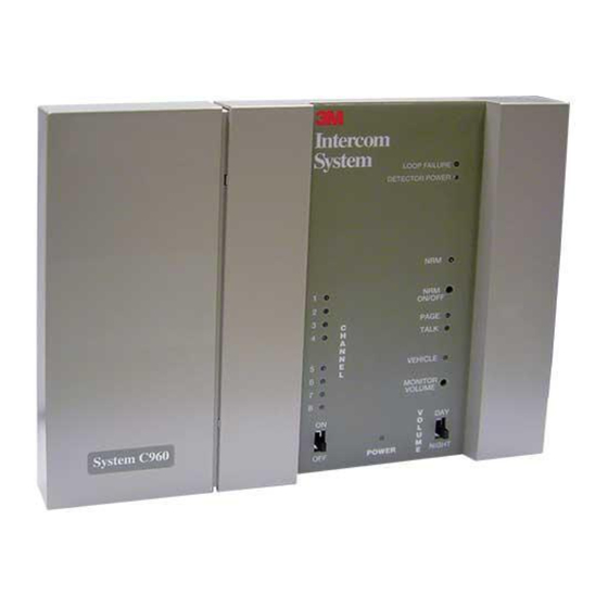
3M C860 Service Information
Wireless intercom system
Hide thumbs
Also See for C860:
- Operating instructions manual (32 pages) ,
- Installation instructions manual (29 pages) ,
- Manual (90 pages)
Summary of Contents for 3M C860
- Page 1 WIRELESS INTERCOM SYSTEM Service Information C960 C1060 Headset Food Services Trade Department Printed in U.S.A 3M 2003 March 3M Center St. Paul, MN 55144-1000 70-0710-3745-4...
-
Page 3: Table Of Contents
Menu Mic Input..........................Base Station Configuration Jumpers and Switches................Base Station and External Components Diagram ................... Interconnect Module ............................1-11 On/Off DC............................1-11 Menu Microphone Signal Control...................... 1-11 Menu Speaker Audio Control ......................1-11 Monitor Speaker Audio Control......................1-11 3M 2003 March... - Page 4 C1060 Installation Instructions Section 3. Replacement Parts and Service Technical Service Base Station Assembly and Interconnect Module C860/C960 - 3-Slot Battery Charger Assembly C860/C960 - 6-Slot Battery Charger Assembly C860 Replacement Parts and Service......................C960 Replacement Parts and Service Headset Assembly ..........................
-
Page 5: Introduction
Introduction eight-ohm cone speaker plus a special weather-resistant dynamic microphone. It also The 3M Wireless Intercom System is designed for includes a mounting bracket for easy mounting in high reliability, compactness, and ease of service. It menu signs, speaker posts and other applications. -
Page 6: Single-Lane Duplex Communication System
Operating Theory headset modulator turns ON only when a talk or page switch is pressed. The 3M Wireless Intercom System has two basic functions. First, it processes vehicle alert signals that The transmitter in the base station is always are supplied by a hard-wired vehicle detection system. -
Page 7: Talk/Listen Communication
Any signal, it re-transmits it to all headset receivers. The audio detected by the headset microphone is same microphone audio signal is also routed to the monitor speaker amplifier if that option has been selected. E 3M 2003 March... -
Page 8: Page Monitor Mode
A one-watt, single-ended monitor amplifier in the base station powers [an optional] speaker which is capable of reproducing the following signals: Talk audio (communications to the menu speaker) Listen audio (communication from the menu speaker) Page audio (internal store communications) E 3M 2003 March... -
Page 9: Base Station
Vehicle Alert System To the monitor speaker amplifier via the MON and Vehicle Detector Input in this section. TALK volume control, through the amplifier and the Master Monitor Volume control to the monitor speaker E 3M 2003 March... -
Page 10: Menu Mic Input
Refer to the must be set for lane 2 frequency communications. Installation Instructions for more information. Jumper J3 pins 1 and 2 (forcing the related logic input high) for lane 1 configuration. Jumper J3 pins 2 and 3 E 3M 2003 March... - Page 11 After a new channel is selected, you must reprogram all system headsets to the new channel. For more information on channel selection and reprogrammning, refer to the Installation Instructions. E 3M 2003 March...
- Page 12 Wireless Intercom System Theory of Operation and Diagrams (Blank Page) E 3M 2003 March...
-
Page 13: Base Station And External Components Diagram
Wireless Intercom System Theory of Operation and Diagrams Base Station and External Components Diagram © 3M 2003 March 1–9... - Page 14 Theory of Operation and Diagrams Wireless Intercom System (Blank Page) © 3M 2003 1–10 March...
-
Page 15: Interconnect Module
With relay detector signal DC will be +12VDC. K301 energized, the menu mic is connected to the base station inputs. With Relay K301 de-energized, the menu mic is connected to the auxiliary intercom. 1- -11 E 3M 2003 March... - Page 16 Theory of Operation and Diagrams Wireless Intercom System (Blank Page) 1- -12 E 3M 2003 March...
- Page 17 Wireless Intercom System Theory of Operation and Diagrams ©3M 2003 March 1-13...
- Page 18 Theory of Operation and Diagrams Wireless Intercom System (Blank Page) 1- -14 E 3M 2003 March...


