Table of Contents
Advertisement
Advertisement
Table of Contents

Related Manuals for Singer 2802


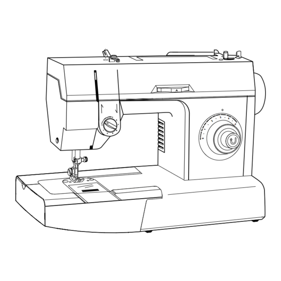
Summary of Contents for Singer 2802
- Page 1 Service Manual Household Sewing Machine 2802/2852 2808/2858 2802/2852 2808/2858 2809/2859 2818/2868 2809/2859 2818/2868 THE SINGER COMPANY 2005 SINGER BRASIL SEWING MACHINE CO., LTD. ALL RIGHTS RESERVED Registered Trademark “THE SINGER COMPANY LTD.” Printed In Brazil 358487-001 Mar./2005...
- Page 2 Service Manual Revisions Records Approval Description Revision and date Rev. n . 358487-001 Mar./2005...
- Page 3 Service Manual This manual is designed for use by trained and qualified service persons. The SINGER COMPANY will not be responsible for any parts requiring replacement due to natural wear or to the abuse or negligence of its use or in the event the machine is serviced by other than a trained and qualified service person or even if replaced parts do not meet applicable specifications.
-
Page 4: General Information
Scope This service manual describes all of the servicing procedures,including all adjustments and parts removal and replacement for the 2802/2852, 2808/2858, 2809/2859 and 2818/2868 models machine. Additional information covering any production changes, improvements or changes to parts will be made by issuing Singer service/parts bulletins. -
Page 5: Table Of Contents
Service Manual Table of Contents Section 1 PAGE Parts removals and replacements............Face plate..................07-08 Light bulb replacement..............07-08 Arm top cover................09-10 Bed bottom cover and end cover............11-12 Needle bar..................13-14 Head end assembly................15-16 Take-up lever assembly and needle bar connecting link......17-18 Handwheel and shaft driver assembly............ - Page 6 Service Manual Table of Contents Section 2 PAGE Sequential order of adjustment procedures ..........Vertical shaft end play ................. 52-53 Bevel gear mesh and arm shaft end play ..........54-55 Disc and disc follower clearance ............56-57 Cam stack radial play ..............56-57 Take-up lever and needle bar connecting link lost motion ......
-
Page 7: Parts Removals And Replacements
Service Manual Section 1 Parts Removal and Replacement Rev. n . 358487-001 Mar./2005... -
Page 8: Face Plate
Service Manual Face Plate Cover Light Bulb Replacement Rev. n . 358487-001 Mar./2005... - Page 9 Service Manual Face Plate Cover Removal: 1. Raise presser foot. 2. Remove face plate cover screw (A). 3. Remove face plate cover (B) by pulling it down and laterally and then out of the machine. Replacement: 1. Replacement of the face plate cover is the same as described above, but in a reverse order.
-
Page 10: Arm Top Cover
Service Manual Arm Top Cover Rev. n . 358487-001 Mar./2005... - Page 11 Service Manual Arm Top Cover Removal: 1. Place bobbin winder in the “OFF” position. 2. Remove two arm top cover screws (A) and (B). 3. Remove the arm top cover by pulling it straight upwards. Replacement: 1. Replacement is the same as removal in reverse order. Rev.
-
Page 12: Bed Bottom Cover And End Cover
Service Manual Bed Bottom Cover (Free Arm) and End Cover Bed Bottom Cover (Flat Bed) Rev. n . 358487-001 Mar./2005... - Page 13 Service Manual End Cover Removal: 1. Remove arm top cover. 2. Remove screw (A). 3. Hold the bottom side of cover (B) and pull it out and up from machine. Replacement: 1. Replacement of this cover is the same as described above, but in a reverse order. Bed Bottom Cover (Free Arm) Removal: 1.
-
Page 14: Needle Bar
Service Manual Needle Bar Rev. n . 358487-001 Mar./2005... - Page 15 Service Manual Needle Bar Removal: 1. Remove the face plate and arm top cover. 2. Remove needle by loosing the screw (B). Turn handwheel to bring the needle bar to its position. Loose screw (A) together with the thread guide and then, remove the entire needle clamp body.
-
Page 16: Head End Assembly
Service Manual Head End Assembly Rev. n . 358487-001 Mar./2005... - Page 17 Service Manual Head End Assembly Removal: 1- Remove face plate, arm top cover and needle. 2- Loosen needle bar driving screw (A). 3- Remove presser foot (D) and presser foot screw (E). 4- Remove light socket mounting screw (H), light socket (G) and light shield (I). 5- Remove three head end mounting screws and washers (C), (F) and (J) .
-
Page 18: Take-Up Lever Assembly And Needle Bar Connecting Link
Service Manual Take-up Lever Assembly and Needle Bar Connecting Link Rev. n . 358487-001 Mar./2005... - Page 19 Service Manual Take-up Lever Assembly and Needle Bar Connecting Link Removal: 1- Remove the face plate cover and arm top cover. 2- Turn hand wheel sufficiently to appear the screw (A). Loosen it. Turn again to appear the screw (B). Loosen it also. 3- Slide take-up lever assembly (C), take-up stud (D) and needle bar connecting link (E).
-
Page 20: Handwheel And Shaft Driver Assembly
Service Manual Handwheel and Shaft Driver Assembly Rev. n . 358487-001 Mar./2005... - Page 21 Service Manual Hand Wheel and Shaft Driver Assembly Removal: 1. Remove arm top cover and right side cover. 2. Remove the hand wheel (A) by pulling it out from machine. 3. Remove the shaft pin (B). 4. Remove retaining ring (C) and washer (D) from shaft. 5.
-
Page 22: Cam Stack
Service Manual Cam Stack 2809/2859 2818/2868 Only 2808/2858 Only 2802/2852 Rev. n . 358487-001 Mar./2005... - Page 23 3. Check left-to-right needle location and bight stops (see pages 68-69 and 72-75), adjust if necessary. 4. Check needle follower clearance (see pages 58-59) Only 2802/2852 Removal: 1. Remove face plate, arm top cover and end cover. 2. Remove handwheel. (See pages 19-20) 3.
-
Page 24: Disc Follower Quick Out Lever
Service Manual Disc Follower Quick Out Lever Except 2802/2852 Disc Follower Except 2802/2852 Rev. n . 358487-001 Mar./2005... - Page 25 Service Manual Disc Follower Quick Out Lever Except 2802/2852 Removal: 1. Remove arm top cover and the stitch width bracket assembly. 2. Remove screw (A) and eccentric bushing (B). 3. Remove lever (D) and spring (C). Replacement: 1. Replace these parts the same way as described above, but in a reverse order.
-
Page 26: Arm Shaft And Horizontal Bevel Gear
Service Manual Arm Shaft and Horizontal Bevel Gear For 2818/2868 Rev. n . 358487-001 Mar./2005... - Page 27 Service Manual Arm Shaft and Horizontal Bevel Gear Removal: 1. Remove face plate, arm top cover and end cover. 2. Remove handwheel. (See pages 19 and 20) 3. Remove head end assembly (See pages 15 and 16) 4. Remove take-up lever assembly and needle bar connecting link. (See pages 17 and 18) 5.
-
Page 28: Pattern Selector Assembly
Service Manual Pattern Selector Assembly Except 2802/2852 Rev. n . 358487-001 Mar./2005... - Page 29 Service Manual Pattern Selector Assembly Except 2802/2852 Removal: 1. Remove the free-arm extension table, all the covers, disc stack shaft gear bracket, disc follower quick out lever and disc follower. 2. Turn the pattern selector dial bringing to sight the screw (A) an then remove this screw.
-
Page 30: Thread Tension Assembly
Service Manual Thread Tension Assembly Rev. n . 358487-001 Mar./2005... - Page 31 Service Manual Thread Tension Assembly Removal: 1. Remove the face plate and arm top cover. 2. Remove the tension mechanism shrouder (A), pulling it forward. Loose de screw (B) and pull out the tension mechanism assembly. 3. Remove the tension dial (N). 4.
-
Page 32: Motor And Motor Belt
Service Manual Motor and Motor Belt Rev. n . 358487-001 Mar./2005... - Page 33 Service Manual Motor and Motor Belt Attention: Make sure the machine is turned off and remove plug from outlet socket before disassemblying Removal: 1. Remove the free arm extension table, bed bottom cover, extension table bottom cover, arm top cover and right side cover. 2.
-
Page 34: Hook
Service Manual Hook Rev. n . 358487-001 Mar./2005... - Page 35 Service Manual Hook Removal: 1. Remove the free-arm extension table (only 2802, 2808, 2809 and 2818 models), all the covers, needle plate and the bobbin case. For other models (Flat Bed) remove slide plate too. 2. Remove feed dog screws (F) and feed dog (E).
-
Page 36: Feed Lifting Lever Assembly
Service Manual Feed Lifting Lever Assembly Rev. n . 358487-001 Mar./2005... - Page 37 2. Turn handwheel toward the front of the machine to bring the feed dog to its furthest rear position. 3. Remove the free-arm extension (only 2802, 2808, 2809 and 2818 models) plate and all the covers. 4. Remove screws (E) to clear the eccentric pin (D) from clamp (F).
-
Page 38: Feed Rock Shaft Assembly
Service Manual Feed Rock Shaft Assembly Rev. n . 358487-001 Mar./2005... - Page 39 Service Manual Feed Rock Shaft Assembly Removal: 1. Remove the free-arm extension table, the thread tension assembly dial, the covers, the needle plate, the feed dog, the feed lifting lever assembly (N), the hook pulley (K) and the belt (M). 2.
-
Page 40: Feed Forked Connection
Service Manual Feed Forked Connection Only 2802/2852 2808/2858 2809/2859 Only 2818/2868 Rev. n . 358487-001 Mar./2005... - Page 41 Service Manual Feed Forked Connection Removal: 1. Remove the free arm extension table, bed bottom cover, extension table bottom cover, arm top cover, right side cover and the hand wheel (see pages 19-20). 2. Remove screw nut ( I ) and the eccentric screw (H). 3.
-
Page 42: Vertical Shaft Bevel Gear
Service Manual Vertical Shaft Bevel Gear ILLUSTRATION “M” Rev. n . 358487-001 Mar./2005... - Page 43 Service Manual Vertical Shaft Bevel Gear Removal: Remove the free arm extension table, all covers, the front head end assembly, the buttonhole assembly, the take-up lever assembly, cam stack and hand wheel. Loosen set screw (E) sufficently to clear vertical shaft bevel gear (A).
-
Page 44: Vertical Shaft
Service Manual Vertical Shaft Rev. n . 358487-001 Mar./2005... - Page 45 Service Manual Vertical Shaft Removal: 1. Remove the free arm extension table, all covers, the head end assembly, the buttonhole assembly, the take-up lever assembly, camstack, hand wheel, horizontal shaft and vertical shaft bevel gear. 2. Loosen the screws (A) of the belt drive pulley (B) sufficiently to remove it. 3.
-
Page 46: Stitch Lenght Control Assembly
Service Manual Stitch Length Control Assembly Except 2818/2868 Stitch Length Control Assembly For 2818/2868 Rev. n . 358487-001 Mar./2005... - Page 47 Service Manual Stitch Length Control Assembly Except 2818/2868 Removal: 1. Remove the free-arm extension table and all the covers. 2. Set feed regulator dial (A) to “5” and remove reverse button (B) and dial (A) pulling them out. 3. Remove two screws (C) and take out stitch lenght control (D). Adjustment: - Set feed regulator dial (A) for maximum stitch length and push on reverse button (B) and release to check if it returns freely.
-
Page 48: Pattern Selector Mechanism
Service Manual Pattern selector mechanism Except 2802/2852 Rev. n . 358487-001 Mar./2005... - Page 49 Service Manual Pattern selector mechanism Except 2802/2852 Removal: 1. Remove arm top cover. 2. Place the handle (B) in the vertical position and pull it up out of the camstack (T). 3. Remove the screws (G) and the camstack gear assembly..
-
Page 50: Needle Position Selector Lever
Service Manual Needle position selector lever For 2818/2868 Rev. n . 358487-001 Mar./2005... - Page 51 Service Manual Needle position selector lever For 2818/2868 Removal: 1. Remove arm top cover. 2. Remove retaining ring (S), the cam controlled feed follower (O) and the retaining ring located under it. 3. Remove link screw (P) through the pattern selector dial hole. 4.
-
Page 52: Sequential Order Of Adjustment Procedures
Service Manual Section 2 Sequential Order of Adjustment Procedures Rev. n . 358487-001 Mar./2005... -
Page 53: Vertical Shaft End Play
Service Manual Vertical Shaft End Play 0,000mm - 0,025mm .000” - .001” Rev. n . 358487-001 Mar./2005... - Page 54 Service Manual Vertical Shaft End Play The vertical shaft must be set to have 0.000 mm - 0.025 mm (.000” - .001”) end play before setting the arm shaft bevel gear and vertical shaft gear mesh. If incorrectly set, noise may be generated.
-
Page 55: Bevel Gear Mesh And Arm Shaft End Play
Service Manual Bevel Gear Mesh and Arm Shaft End Play Rev. n . 358487-001 Mar./2005... - Page 56 Service Manual Bevel Gear Mesh and Arm Shaft End Play The arm shaft should not have any perceptible shake or end play when assembled in the machine and should rotate freely without binds. Check: 1. Remove bed bottom cover, extension table bottom cover, arm top cover and right side cover.
-
Page 57: Disc And Disc Follower Clearance
Service Manual Disc and Disc Follower Clearance Except 2802/2852 0,2mm - 0,3mm .007” - .011” Cam Stack Radial Play Except 2802/2852 Rev. n . 358487-001 Mar./2005... - Page 58 Service Manual Disc and Disc Follower Clearance Except 2802/2852 The disc follower should be adjusted so that 0,2 - 0,3 mm (.007" - .0 ") play is obtained between its contact point and the top of the disc tooth. Check: 1.
-
Page 59: Take-Up Lever And Needle Bar Connecting Link Lost Motion
Service Manual Take-up Lever and Needle Bar Connecting Link Lost Motion Rev. n . 358487-001 Mar./2005... - Page 60 Service Manual Take-up Lever and Needle Bar Connecting Link Lost Motion Looseness in either or the take-up lever and needle bar connecting link will cause the machine to run noisy and may cause irregular stitching. Check: 1. Remove needle and presser foot. 2.
-
Page 61: Needle Bar Bearings
Service Manual Needle Bar Bearings Rev. n . 358487-001 Mar./2005... - Page 62 Service Manual Needle Bar Bearings Looseness of the needle bar bearings will cause irregular stitching and may cause needle breakage. Check: 1. Turn hand wheel toward front of the machine to bring needle bar to its lowest position. 2. Grasp needle clamp (C) and check for excessive front-to-back play. 3.
-
Page 63: Needle Bar Height
Service Manual Needle Bar Height 0,40mm - 0,80mm Rev. n . 358487-001 Mar./2005... - Page 64 Service Manual Needle Bar Height Three rings are cut into the upper end of the needle bar. The distance between the center and lower ring represents the rise required to form a thread loop at the eye of the needle required for hook point seizure.
-
Page 65: Needle Bar Pendulum Timing
Service Manual Needle Bar Pendulum Timing Except 2802/2852 5,5 mm - 7,5 mm .220” - .300” Rev. n . 358487-001 Mar./2005... - Page 66 Service Manual Needle Bar Pendulum Timing Except 2802/2852 Check: 1. Set the machine for zig-zag, maximum width. 2. Remove the presser foot. 3. With the presser bar in a raised position, hold a piece of paper in place over the needle plate, so needle penetration may be observed.
-
Page 67: Zigzag Centralizing Procedure
Service Manual Zigzag Centralizing Procedure ILLUSTRATION F For 2802/2852 Rev. n . 358487-001 Mar./2005... - Page 68 5. Move needle bar (B) to right or left reducing or increasing the lateral clearance as necessary, see illustration "F". 6. Without disturbing the position of the needle bar (B), tighten screw (A). 7. Recheck and readjust if necessary. For 2802/2852 Check: 1. Set the machine for zig-zag, maximum width. 2. Remove the presser foot.
-
Page 69: Needle Location In The Needle Plate Slot
Service Manual Needle Location in the Needle Plate Slot NEEDLE SIZE 14 ILLUSTRATION “A” Only 2802/2852 NEEDLE SIZE 14 ILLUSTRATION “B” Rev. n . 358487-001 Mar./2005... - Page 70 (.007") clearance between the needle and the needle plate slot edge, as shown in the illustration "A". 5. Tighten screw (A). Only 2802/2852 When a needle size 14 penetrates the needle plate slot it must remain approximately in the center of that opening.
-
Page 71: Needle To Hook Relationship
Service Manual Needle to Hook Relationship 0,00 mm INTERFERENCE 0,10 mm CLEARANCE .000” INTERFERENCE .004” CLEARANCE ILLUSTRATION “A" Rev. n . 358487-001 Mar./2005... - Page 72 Service Manual Needle to Hook Relationship Proper needle to hook relationship is required to prevent skipping of stitches on various fabrics and to prevent hook and needle damage. If the needle is too far from the hook, the hook point will be unable to pick up the needle thread loop and skipping of stitches will occur.
- Page 73 Service Manual Maximum Width Zigzag Lever Bight Stop Except 2808/2858 Only 2802/2852 Rev. n . 358487-001 Mar./2005...
- Page 74 Service Manual Maximum Width Zigzag Lever Bight Stop Except 2808/2858 Check: 1. Set the machine for zigzag. 2. Rotate handwheel to make needle penetrate on both left and right sides of a paper; than measure the distance between the holes are to be 5,6 to 6,0 mm. 3.
-
Page 75: Needle Bar Safety Bight Stop (Left Side)
Service Manual Needle Bar Safety Bight Stop (Left Side) Rev. n . 358487-001 Mar./2005... - Page 76 Service Manual Needle Bar Safety Bight Stop (Left Side) When sewing width zigzag, the needle bar must not contact the needle bar safety stop screw. The point of a size 18 needle must not strike the throat plate when the needle bar is in its extreme left position but should deflect slightly into the throat plate hole when in the extreme left needle position.
-
Page 77: Presser Bar Height And Alignment
Service Manual Presser Bar Height and Alignment Rev. n . 358487-001 Mar./2005... - Page 78 Service Manual Presser Bar Height and Alignment Presser bar height and alignment must be correct to insure proper operation of attachments and provide straight controlled feeding qualities. Check. 1. Remove needle. 2. Raise presser foot to its heighest position. 3. Presser bar height is correct when the distance between the underside of the presser foot and the needle plate is 7,35 mm - 7,60 mm (.290"...
-
Page 79: Hook Drive Belt Tension
Service Manual Hook Drive Belt Tension 8,60 - 10,20 mm (.338” - .400”) 140 - 144 g (5.0 - 5.14 oz) Rev. n . 358487-001 Mar./2005... - Page 80 Service Manual Hook Drive Belt Tension Check: 1. The hook drive belt tension should be such that a weight of 140 g (5 oz.) centrally located between the pulleys, deflects the belt 8,6 mm - 10,2 mm (.338” - .400”). Adjustment: 1.
-
Page 81: Hook Timing (Hook And Needle Synchronism)
Service Manual Hook Timing (Hook and Needle Synchronism) Rev. n . 358487-001 Mar./2005... - Page 82 Service Manual Hook Timing (Hook and Needle Synchronism) Before hook timing is attempted, needle location (page 70-71), needle to hook relationship (page 72-73) and hook drive belt tension (page 80-81) must be correct. Check: 1. Remove face plate, presser foot, needle, needle plate and bobbin case. 2.
- Page 83 Service Manual Bobbin Case Position Finger and Bobbin Case Position Plate 0,25mm 0,36mm Rev. n . 358487-001 Mar./2005...
-
Page 84: Bobbin Case Position Finger
Service Manual Bobbin Case Position Finger Check: 1. Position finger (A) must not extend above the left fork of the bobbin case but must be flush with the surface. Adjustment: 1. Adjust the finger position as necessary to obtain the correct location or replace the position bracket (C), if necessary. -
Page 85: Bobbin Case Clearance
Service Manual Bobbin Case Clearance RETAINING PLATE (A) 0,25 - 0,36 mm BOBBIN CASE POSITION PLATE (C) 0,25 - 0,36 mm BOBBIN CASE Rev. n . 358487-001 Mar./2005... - Page 86 Service Manual Bobbin Case Clearance Check: Remove needle plate. 2. Turn handwheel toward the front of the machine to bring hook point to position (D). 3. Place the rear of the bobbin case against the bobbin case position plate (C). 4.
-
Page 87: Needle Thread Tension
Service Manual Needle Thread Tension Rev. n . 358487-001 Mar./2005... -
Page 88: Machine Setting
Service Manual Needle Thread Tension Machine setting: 1. Straight stitch, 2 mm stitch length (12 stitches per inch). 2. Center needle position. 3. Machine threaded for sewing. Check: 1. The thread take-up spring (C) must be set to come to rest against take-up spring stop (B) between the time of the needle point penetration and needle eye entrance into 1-ply of light weight fabric (illustration 1) . -
Page 89: Bobbin Winder
Service Manual Bobbin Winder 1,5 mm (1/16”) ILLUSTRATION "K" ILLUSTRATION "L" ILLUSTRATION "M" Rev. n . 358487-001 Mar./2005... - Page 90 Service Manual Bobbin Winder Check: 1. Run machine and push bobbin winder spindle (A) to the left (OFF position). 2. Place empty bobbin on bobbin winder spindle (A). 3. Push bobbin winder from side to side in side opening (D). At no time should any part of the bobbin winder or the bobbin touch either the opening or the bobbin winder stop (C).
-
Page 91: Feed Rock Shaft End Play
Service Manual Feed Rock Shaft End Play Rev. n . 358487-001 Mar./2005... - Page 92 Service Manual Feed Rock Shaft End Play There must be no end play or binds in feed rock shaft (C). Check: 1. Remove the free arm extension table, bed bottom cover and extension table bottom cover. 2. Move feed rock shaft (C) left to right to check for end play. Adjustment: 1.
- Page 93 Service Manual Feed Dog Centralization and Feed Dog Height 1,00mm 1,20mm .040’’ .047’’ Rev. n . 358487-001 Mar./2005...
-
Page 94: Feed Dog Centralization
Service Manual Feed Dog Centralization Check: 1. Set the machine to straight stitch, maximum stitch length. 2. Turn the handwheel toward the front of the machine to bring feed dog (A) to its highest point. Check and confirm that the drop-in feed selector lever is displaced to the right (feed dog at higest position). -
Page 95: Feed Dog Throw
Service Manual Feed Dog Throw 0,38mm 0,50mm .015” .020” Rev. n . 358487-001 Mar./2005... - Page 96 Service Manual Feed Dog Throw Check: 1. Set the machine to maximum stitch length. 2. Turn handwheel toward the front of the machine until feed dog (A) is in its most forward position. 3. There should be a clearance of 0,38 mm - 0,50 mm between the center bar of feed dog (A) and the edge of the center slot of the needle plate.
-
Page 97: Stitch Length Regulator Spring Tension
Service Manual Stitch length regulator spring tension For 2818/2868 Rev. n . 358487-001 Mar./2005... - Page 98 Service Manual Stitch length regulator spring tension For 2818/2868 The reverse button must operate smoothly with the stitch length set at maximum stitch. Adjustment; 1. Remove arm top cover, right side cover, motor belt and hand wheel. 2. Loosen screw (A) in feed regulator assembly. 3.
-
Page 99: Motor Belt Tension
Service Manual Motor Belt Tension Rev. n . 358487-001 Mar./2005... - Page 100 Service Manual Motor Belt Tension Too tight a motor belt tension can cause the machine to run slow and will overload the motor. Too loose a motor belt tension will create belt noise and may cause jumping of the belt teeth on cogged motor pulley. Adjustment: 1- Remove arm top cover and right side cover.
-
Page 101: Zero Feed
Service Manual Zero Feed Except 2818/2868 Rev. n . 358487-001 Mar./2005... - Page 102 Service Manual Zero Feed Except 2818/2868 Check: 1. Remove needle. 2. Place a 2-plies of light-weight fabric over the needle plate. 3. Set stitch length control dial (B) to "0" (zero). 4. Set reverse button mark (C) in line with reference mark (A) on the front cover. 5.
- Page 103 Service Manual Zero Feed For 2818/2868 Rev. n . 358487-001 Mar./2005...
- Page 104 Service Manual Zero Feed For 2818/2868 Check: 1. Remove needle. 2. Place a 2-plies of light-weight fabric over the needle plate. 3. Set stitch length control dial (B) to "O" (zero). 4. Set reverse button with indicator mark (C) in line with reference mark (A) on the cover. 5.
-
Page 105: Lubrication
Service Manual Lubrication Rev. n . 358487-001 Mar./2005... - Page 106 Service Manual Lubrication Only 2802/2852 Rev. n . 358487-001 Mar./2005...
- Page 107 Service Manual Lubrication Rev. n . 358487-001 Mar./2005...
- Page 108 Service Manual Lubrication Rev. n . 358487-001 Mar./2005...
- Page 109 In order to meet the customer minimum lubrication requirement, the machine must be lubricated as indicated on pages 104/105/106/107. Only Singer oil and Singer grease must be used. Use of parafin based oil, or non-silicon type grease, will create a build up of residue on the bearing surfaces.
-
Page 110: Flexi Stitch Zeroing
Service Manual Flexi stitch zeroing Only 2818/2868 Rev. n . 358487-001 Mar./2005... -
Page 111: Machine Settings
Service Manual Flexi stitch zeroing Only 2818/2868 Machine settings: 1. Stitch selection: straight stretch stitch. 2. Stitch width: straight stitch. 3. Stitch length:Turn dial to left until the indicator mark printed on it ( ) is aligned with the dot in the front cover ( 4. -
Page 112: Buttonhole Cutting Space
Service Manual Buttonhole cutting space Only 2818/2868 0,50mm - 1,00mm (.020” - .040”) 0,50mm - 1,00mm (.020” - .040”) ILLUSTRATION “D” Rev. n . 358487-001 Mar./2005... - Page 113 Service Manual Buttonhole cutting space Only 2818/2868 To allow sufficient space for cutting without damaging the thread, the buttonhole cutting space must be approximately 0,50 mm - ,00 mm ( .020" - .040") . Check: Remove presser foot. 2. Insert a number 9 needle to provide better visibility and accuracy when checking buttonhole cutting space.