Table of Contents
Advertisement
Quick Links
Advertisement
Chapters
Table of Contents
Troubleshooting

Related Manuals for Suzuki VL125


Summary of Contents for Suzuki VL125
- Page 1 VL125 loc83 9 9 5 0 0 - 3 1 1 5 0 - 0 1 E...
-
Page 2: General Information
FOREWORD GROUP INDEX This manual contains an introductory description on the SUZUKI VL125 and procedures for its inspec- tion/service and overhaul of its main components. GENERAL INFORMATION Other information considered as generally known is not included. Read the GENERAL INFORMATION section to fa-... -
Page 3: How To Use This Manual
HOW TO USE THIS MANUAL TO LOCATE WHAT YOU ARE LOOKING FOR: 1.The text of this manual is divided into sections. 2.The section titles are listed in the GROUP INDEX. 3.Holding the manual as shown at the right will allow you to find the first page of the section easily. - Page 4 “1303”. Indication of service data. 99000-32030 Apply THREAD LOCK “1342”. 99000-32050 * How to make Molybdenum oil : Pour an engine oil and SUZUKI MOLY PASTE in a ratio of 1:1 by volume into such as oiler, and stir well.
-
Page 5: Table Of Contents
GENERAL INFORMATION 1-1 GENERAL INFORMATION CONTENTS WARNING/CAUTION/NOTE ............... 1- 2 GENERAL PRECAUTIONS ..............1- 2 SUZUKI VL125Y (2000-MODEL) ............1- 4 SERIAL NUMBER LOCATION ............1- 4 FUEL AND OIL RECOMMENDATION ..........1- 5 FUEL....................1- 5 ENGINE OIL ..................1- 5 BRAKE FLUID ................. -
Page 6: Warning/Caution/Note
1-2 GENERAL INFORMA 1-2 GENERAL INFORMA TION TION 1-2 GENERAL INFORMA 1-2 GENERAL INFORMA 1-2 GENERAL INFORMATION TION TION WARNING/CAUTION/NOTE Please read this manual and follow its instructions carefully. To emphasize special information, the symbol and the words WARNING, CAUTION and NOTE have special meanings. Pay special attention to the mes- sages highlighted by these signal words. - Page 7 GENERAL INFORMATION 1-3 GENERAL INFORMATION 1-3 * If parts replacement is necessary, replace the parts with Suzuki Genuine Parts or their equiva- lent. * When removing parts that are to be reused, keep them arranged in an orderly manner so that they may be reinstalled in the proper order and orientation.
-
Page 8: Suzuki Vl125Y (2000-Model)
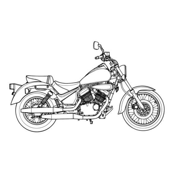
1-4 GENERAL INFORMA 1-4 GENERAL INFORMA 1-4 GENERAL INFORMATION TION TION SUZUKI VL125Y (2000-MODEL) LEFT SIDE RIGHT SIDE *Difference between photograph and actual motorcycle depends on the markets. SERIAL NUMBER LOCATION The frame serial number or V.I.N. (Vehicle Identification Number) 1 is stamped on the right side of the frame tube. -
Page 9: Fuel And Oil Recommendation
GENERAL INFORMATION 1-5 GENERAL INFORMATION 1-5 GENERAL INFORMATION 1-5 GENERAL INFORMATION 1-5 GENERAL INFORMATION 1-5 FUEL AND OIL RECOMMENDATION FUEL Gasoline used should be graded 91 octane (Research Method) or higher. Unleaded gasoline is recom- mended. ENGINE OIL Use a premium quality 4-stroke motor oil to ensure longer ser- vice life of your motorcycle. -
Page 10: Cylinder Identification
1-6 GENERAL INFORMA 1-6 GENERAL INFORMA TION TION 1-6 GENERAL INFORMA 1-6 GENERAL INFORMA 1-6 GENERAL INFORMATION TION TION CYLINDER IDENTIFICATION No. 1 No. 1 No. 2 No. 2 The two cylinders of this engine are identified as No. 1 and No. 2 cylinder, as counted from rear to front (as viewed by the rider on the seat). -
Page 11: Specifications
GENERAL INFORMATION 1-7 GENERAL INFORMATION 1-7 GENERAL INFORMATION 1-7 GENERAL INFORMATION 1-7 GENERAL INFORMATION 1-7 SPECIFICATIONS DIMENSIONS AND DRY MASS Overall length ............2 240 mm Overall width ............880 mm Overall height ............1 110 mm Wheelbase ............1 520 mm Ground clearance .......... - Page 12 1-8 GENERAL INFORMA 1-8 GENERAL INFORMA TION TION 1-8 GENERAL INFORMA 1-8 GENERAL INFORMA 1-8 GENERAL INFORMATION TION TION ELECTRICAL Ignition type ............Electronic ignition (Transistorized) Ignition timing ............10° B.T.D.C. at 1 400 r/min Spark plug ............NGK CR8E or DENSO U24ESR-N Battery ..............
-
Page 13: Country And Area Codes
GENERAL INFORMATION 1-9 GENERAL INFORMATION 1-9 GENERAL INFORMATION 1-9 GENERAL INFORMATION 1-9 GENERAL INFORMATION 1-9 COUNTRY AND AREA CODES The following codes stand for the applicable country(-ies) and area(-s). CODE COUNTRY or AREA E-02 U.K. E-04 France E-17 Sweden, Finland (E-15), Norway (E-16), Denmark (E-26) E-22 Germany E-34... -
Page 14: Periodic Maintenance
PERIODIC MAINTENANCE 2-1 PERIODIC MAINTENANCE CONTENTS PERIODIC MAINTENANCE SCHEDULE ..........2- 2 PERIODIC MAINTENANCE CHART ..........2- 2 LUBRICATION POINTS ..............2- 3 MAINTENANCE AND TUNE-UP PROCEDURES ......... 2- 4 VALVE CLEARANCE ..............2- 4 SPARK PLUG ................. 2- 6 EXHAUST PIPE BOLTS AND MUFFLER BOLTS ...... -
Page 15: Periodic Maintenance Schedule
2-2 PERIODIC MAINTENANCE PERIODIC MAINTENANCE SCHEDULE The chart below lists the recommended intervals for all the required periodic service work necessary to keep the motorcycle operating at peak performance and economy. Maintenance intervals are expressed in terms of kilometers and months, and are dependant on whichever comes first. NOTE: More frequent servicing may be performed on motorcycles that are used under severe conditions. -
Page 16: Lubrication Points
PERIODIC MAINTENANCE 2-3 LUBRICATION POINTS Proper lubrication is important for smooth operation and long life of each working part of the motorcycle. Major lubrication points are indicated below. Clutch lever holder Side-stand pivot and spring hook Drive chain Throttle cable Brake lever holder end and pully Brake pedal pivot... -
Page 17: Maintenance And Tune-Up Procedures
2-4 PERIODIC MAINTENANCE MAINTENANCE AND TUNE-UP PROCEDURES This section describes the servicing procedures for each item of the Periodic Maintenance requirements. VALVE CLEARANCE Inspect initially at 1 000 km (5 months) and every 4 000 km (20 months). INSPECTION NOTE: The clearance specification is for COLD state. - Page 18 PERIODIC MAINTENANCE 2-5 • Remove the generator cover plug 1 and the timing inspection plug 2. " Generator cover plug: 15 N . m (1.5 kgf . m) Timing inspection plug: 21 N . m (2.1 kgf . m) NOTE: To turn the crankshaft for clearance checking, and rotate in the normal running direction.
-
Page 19: Spark Plug
2-6 PERIODIC MAINTENANCE SPARK PLUG Clean every 4 000 km (20 months) and replace every 8 000 km (40 months). REMOVAL • Disconnect the spark plug caps. • Remove the spark plugs. % 09930-10121: Spark plug socket wrench set Standard Cold type Hot type CR8E... -
Page 20: Exhaust Pipe Bolt And Muffler Bolt
PERIODIC MAINTENANCE 2-7 EXHAUST PIPE BOLT AND MUFFLER BOLT Tighten initially at 1 000 km (5 months) and every 4 000 km (20 months) thereafter. • Tighten the exhaust pipe bolts 1, muffler connecting bolts 2 and muffler mounting bolts 3 to the specified torque with a torque wrench. - Page 21 2-8 PERIODIC MAINTENANCE • Remove the left air cleaner element 3. CLEANING • Fill a washing pan of a proper size with a non-flammable clean- ing solvent. Immerse the element in the cleaning solvent and wash it. • Gently squeeze the element to remove the excess solvent: do not twist or wring the element or it will develop tears.
-
Page 22: Carburetor
PERIODIC MAINTENANCE 2-9 CARBURETOR IDLE RPM (Idling adjustment) Inspect initially at 1 000 km (5 month) and every 4 000 km (20 months) thereafter. NOTE: Make this adjustment when the engine is hot. • Connect an electric tachometer to the high-tension cord. •... -
Page 23: Fuel Hose
2-10 PERIODIC MAINTENANCE • Loosen the lock nuts 4 of the throttle pulling cable 5. • Turn the pulling cable adjuster 6 in or out until the throttle cable play should be 2.0 – 4.0 mm at the throttle grip. •... -
Page 24: Engine Oil And Oil Filter
PERIODIC MAINTENANCE 2-11 ENGINE OIL AND OIL FILTER (ENGINE OIL) Replace initially at 1 000 km (5 months) and every 4 000 km (20 months) thereafter. (OIL FILTER) Replace initially at 1 000 km (5 months) and every 8 000 km (40 months) thereafter. - Page 25 Use SUZUKI MOTORCYCLE GENUINE OIL FILTER only, since the other make’s genuine filters and after-market parts may differ filtering performance and durability, which could cause engine damage or oil leaks. Suzuki automobile genuine oil filter is also not usable for the motorcycles.
-
Page 26: Drive Chain
PERIODIC MAINTENANCE 2-13 DRIVE CHAIN Inspect initially at 1 000 km (5 months) and every 4 000 km (20 months) thereafter. Clean and lubricate every 1 000 km. Visually check the drive chain for the possible defects listed be- low. (Support the motorcycle by a jack and a wooden block, turn the rear wheel slowly by hand with the transmission shifted to Neutral.) * Loose pins... -
Page 27: Adjusting
* Do not use any oil sold commercially as “drive chain oil”. Such oil can damage the “O”-rings (or seals). * The standard drive chain is a RK428 H0 Suzuki recom- mends that this standard drive chain should be used... -
Page 28: Brake System
PERIODIC MAINTENANCE 2-15 BRAKE SYSTEM (BRAKE) Inspect initially at 1 000 km (5 months) and every 4 000 km (20 months) thereafter. (BRAKE HOSE AND BRAKE FLUID) Inspect initially at 1 000 km (5 months) and every 4 000 km (20 months). Replace hoses every 4 years. Replace fluid every 2 years. - Page 29 2-16 PERIODIC MAINTENANCE FRONT BRAKE PAD REPLACEMENT • Remove the brake caliper and brake pad pin 1. • Remove the brake pads. • To reassemble, reverse the above sequence. " Brake caliper mounting bolt: 39 N . m (3.9 kgf . m) Brake pad pin: 18 N .
- Page 30 PERIODIC MAINTENANCE 2-17 AIR BLEEDING THE BRAKE FLUID CIRCUIT Air trapped in the brake fluid circuit acts like a cushion to absorb a large proportion of the pressure developed by the master cylin- der and thus interferes with the full braking performance of the brake caliper.
- Page 31 2-18 PERIODIC MAINTENANCE REAR BRAKE PEDAL HEIGHT • Loosen the lock nut 1. • Adjust the brake pedal height A by turning the adjuster 2. # Rear brake pedal height A: 50 – 60 mm REAR BRAKE ADJUSTING • Adjust the free travel B to 20 – 30 mm by turning the adjusting nut 3.
-
Page 32: Steering
PERIODIC MAINTENANCE 2-19 STEERING Inspect initially at 1 000 km (5 months) and every 8 000 km (40 months) thereafter. Steering should be adjusted properly for smooth turning of handlebars and safe running. Overtight steering prevents smooth turning of the handlebars and too loose steering will cause poor stability. -
Page 33: Tire
The standard tire fitted on this motorcycle is 90/90–18 51P for front and 130/90–15M/C 66P for rear. The use of tires other than those specified may cause instability. It is highly recommended to use a SUZUKI Genuine Tire. TIRE TYPE Front: IRC GS-21F... -
Page 34: Compression Pressure Check
PERIODIC MAINTENANCE 2-21 COMPRESSION PRESSURE CHECK The compression of a cylinder is a good indicator of its internal condition. The decision to overhaul the cylinder is often based on the re- sults of a compression test. Periodic maintenance records kept at your dealership should include compression readings for each maintenance service. -
Page 35: Oil Pressure Check
2-22 PERIODIC MAINTENANCE OIL PRESSURE CHECK Check the oil pressure periodically. This will give a good indication of the condition of the moving parts. OIL PRESSURE SPECIFICATION 35 – 60 kPa (0.35 – 0.60 kgf/cm ) at 3 000 r/min., Oil temp. at 60°C (140°F) If the oil pressure is lower or higher than the specification, the following causes may be considered. - Page 36 ENGINE 3-1 ENGINE CONTENTS ENGINE COMPONENTS REMOVABLE WITH ENGINE IN PLACE ..3- 2 ENGINE REMOVAL AND REINSTALLATION ......... 3- 3 ENGINE REMOVAL ..............3- 3 ENGINE REINSTALLATION ............3- 8 ENGINE DISASSEMBLY..............3-11 ENGINE COMPONENT INSPECTION AND SERVICE ....3-20 CYLINDER HEAD COVER ............
-
Page 37: Engine Components Removable With Engine In Place
3-2 ENGINE ENGINE COMPONENTS REMOVABLE WITH ENGINE IN PLACE The parts listed below can be removed and reinstalled without removing the engine from the frame. Refer to page listed in each section for removal and reinstallation instructions. ENGINE CENTER ITEM REMOVAL INSPECTION REINST ALLA TION Air cleaner box... -
Page 38: Engine Removal And Reinstallation
ENGINE 3-3 ENGINE REMOVAL AND REINSTALLATION ENGINE REMOVAL NOTE: If the engine is dirtied, wash the machine with a steam cleaner before removing the engine. • Remove the front seat. (95-2) • Remove the luggage box. (95-2) • Remove the fuel tank. (94-3) •... - Page 39 3-4 ENGINE • Loosen the clamp screw. • With the bolts removed, take out the center air cleaner box. CARBURETOR • Remove the carburetor. (94-12) • Disconnect the vacuum hoses 1 and 2 from the intake pipe. CLUTCH CABLE • Disconnect the clutch cable end out of clutch lever. •...
- Page 40 ENGINE 3-5 EXHAUST PIPE AND MUFFLER • With the exhaust pipe bolts and muffler bolts removed, re- move the exhaust pipes and mufflers. ELECTRIC PARTS • Remove the spark plug caps. • Remove the starter motor lead wire. • Remove the engine ground lead wire 1. •...
- Page 41 3-6 ENGINE • Disconnect the signal generator coupler 3, generator cou- pler 4 and gear position switch coupler 5. ENGINE SPROCKET • Remove the engine sprocket cover. • Remove the breather hose. • With the bolt removed, disconnect the gearshift arm. •...
- Page 42 ENGINE 3-7 • Remove the engine sprocket. NOTE: If it is difficult to remove the engine sprocket, loosen the rear axle nut, rear torque link nuts and chain adjusters to provide additional chain slack. ( 9 2-13) • Support the engine using an engine jack. •...
-
Page 43: Engine Reinstallation
3-8 ENGINE ENGINE REINSTALLATION Reinstall the engine in the reverse order of engine removal. • Install the engine mounting bolts and nuts as shown in the following illustration. • Tighten the engine mounting bolts and nuts to the specified torque. NOTE: The engine mounting nuts are self-locking. - Page 44 ENGINE 3-9 ENGINE SPOCKET • Loosen the rear axle nut, rear torque link nuts and chain ad- justers. • Install the engine sprocket. • Tighten the engine sprocket nut 1 to the specified torque. " Engine sprocket nut: 90 N . m (9.0 kgf . m) NOTE: When tightening the engine sprocket nut, depress the rear brake pedal.
- Page 45 3-10 ENGINE • Install the exhaust pipes and mufflers as shown in the following illustration. Apply PERMATEX 1372 to the inside and outside. " kgf . m N . m ITEM • Install the carburetor and air cleaner. (94-6) • After remounting the engine, the following adjustments are necessary.
-
Page 46: Engine Disassembly
ENGINE 3-11 ENGINE DISASSEMBLY STARTER MOTOR • Remove the starter motor. GEAR POSITION SWITCH • Remove the gear position switch. • Remove the contacts 1, 2 and springs 3, 4. SPEED SENSOR • Remove the speed sensor. CYLINDER HEAD COVER •... - Page 47 3-12 ENGINE • Remove the valve inspection caps. • Remove the front cylinder head cover. NOTE: When removing the cylinder head covers, the piston must be at top dead center on the compression stroke. ( 9 2-4) No. 2 (FRONT) •...
- Page 48 ENGINE 3-13 INTAKE PIPE • Remove the intake pipe 1. CYLINDER HEAD AND CYLINDER • With the cylinder head nuts removed, remove the No. 1 (Rear) cylinder. • Remove the gasket 1, cam chain guide 2 and cylinder. • Remove the No. 2 (Front) cylinder head and cylinder in same manner of No.
- Page 49 3-14 ENGINE PISTON • Place a clean rag over the cylinder base to prevent piston pin circlips from dropping into the crankcase. Remove the piston pin circlips with long-nose pliers. • Drive out the piston pins by using proper drift. NOTE: Scribe the cylinder position on the head of the respective pis- tons.
- Page 50 ENGINE 3-15 • Remove the key 1. • Remove the starter driven gear 2. • Remove the cam chain tensioner 3 and cam chain 4. CLUTCH COVER • Remove the clutch release arm 1. • Remove the clutch cover bolts. •...
- Page 51 3-16 ENGINE • Remove the clutch drive and driven plates. • Flatten the lock washer 2. • With the clutch sleeve hub held immovable using special tool, remove the clutch sleeve hub nut. % 09920-53740: Clutch sleeve hub holder • Remove the clutch sleeve hub 3 and primary driven gear as- sembly 4.
- Page 52 ENGINE 3-17 PRIMARY DRIVE GEAR • With the generator rotor held immovable using special tool, re- Loosening Loosening move the primary drive gear nut. direction direction ! 09930-44530: Rotor holder " This bolt has left-hand thread. Turning it counterclock- wise, it may cause damage. •...
- Page 53 3-18 ENGINE GEARSHIFT SHAFT • With the circlip 1 removed, draw out the gearshift shaft. • Remove the gearshift cam stopper plate 2. • Remove the gearshift cam stopper 3 with spring. • Remove the gearshift arm stopper 4. • Remove the oil seal retainer and drive shaft spacer 5. •...
- Page 54 ENGINE 3-19 • Separate the crankcase into 2 parts, right and left, with a crank- case separating tool. ! 09920-13120: Crankcase separator NOTE: Fit the crankcase separating tool, so that the tool arms parallel the side of the crankcase. The crankshaft and transmission com- ponents must remain in the left crankcase half.
-
Page 55: Engine Component Inspection And Service
3-20 ENGINE ENGINE COMPONENT INSPECTION AND SERVICE " Be sure to identify each removed part as to its location, and lay the parts out in groups designated as “No. 1 cyl- inder”, “No. 2 cylinder”, “Exhaust”, “Intake”, so that each will be restored to the original location during assembly. - Page 56 ENGINE 3-21 INSPECTION CYLINDER HEAD COVER DISTORTION After removing sealant from the fitting surface of the cylinder head cover, place the cylinder head cover on a surface plate and check for distortion with a thickness gauge. # Cylinder head cover distortion: Service Limit: 0.05 mm ! 09900-20803: Thickness gauge If the distortion exceeds the limit, replace the cylinder head cover.
-
Page 57: Camshaft
3-22 ENGINE CAMSHAFT CAM WEAR INSPECTION Check for abnormal surface damage or wear on the cam face. Measure the cam height H with a micrometer. Replace the camshaft if found worn down to the service limit. # Cam height H: Service Limit: (IN) 32.57 mm (EX) Front: 32.60 mm Rear : 32.33 mm CAMSHAFT JOURNAL WEAR INSPECTION... -
Page 58: Cam Chain Tension Adjuster
ENGINE 3-23 CAMSHAFT RUNOUT With the camshaft held on the V-blocks, measure the runout with a dial gauge. If the runout exceeds the service limit, replace the camshaft. # Camshaft runout: Service Limit: 0.10 mm ! 09900-20606: Dial gauge (1/100 mm) 09900-20701: Magnetic stand 09900-21304: V-block set (100 mm) CAM CHAIN TENSION ADJUSTER... -
Page 59: Cylinder Head
3-24 ENGINE CYLINDER HEAD DISASSEMBLY • Remove the exhaust pipe and gasket. • Compress the valve spring using the special tool. ! 09916-14510: Valve lifter 09916-14910: Attachment 09916-84511: Tweezers • Remove the valve cotter halves 1. • Remove the valve spring retainer 2. •... - Page 60 ENGINE 3-25 INSPECTION CYLINDER HEAD DISTORTION Check for distortion of the mating surface diagonally with a straight- edge and thickness gauge as shown. If distortion exceeds the service limit, repair or replace the cylin- der head. # Cylinder head distortion: Service Limit: 0.05 mm ! 09900-20803: Thickness gauge VALVE STEM RUNOUT Check the valve stem for abnormal wear or bend.
- Page 61 3-26 ENGINE VALVE STEM DEFLECTION With the valve inserted into the valve guide, lift the valve head 10 mm from the valve seat and measure the deflection in X and Y directions. # Valve stem deflection (IN & EX): Service Limit: 0.35 mm ! 09900-20606: Dial gauge (1/100 mm) 09900-20701: Magnetic stand VALVE STEM DIAMETER...
- Page 62 ENGINE 3-27 VALVE GUIDE SERVICING • Using the valve guide remover 1, drive the valve guide out toward the intake or exhaust camshaft side. ! 09916-43210: Valve guide remover/installer NOTE: * Discard the remove valve guide subassemblies. * Only oversized valve guides are available as replacement parts. (Part No.
- Page 63 3-28 ENGINE VALVE SEAT WIDTH INSPECTION Visually check for valve seat width on each valve face. If the valve face has worn abnomally, replace the valve. Coat the valve seat with Prussian Blue and set the valve in place. Rotate the valve with light pressure. Check that the transferred blue on the valve face is uniform all around and in center of the valve face.
- Page 64 ENGINE 3-29 • When installing the solid pilot 1, rotate it slightly. • Seat the pilot snugly. Install the 45° cutter 2 and T-handle 3. INITIAL SEAT CUT • Using the 45° cutter, descale and clean up the seat. Rotate the cutter one or two turns.
- Page 65 3-30 ENGINE TOP NARROWING CUT Contact area too high and too wide on face of valve • If the contact area is too high on the valve, or if it is too wide, use the 15° or 32° cutter to lower and narrow the contact area. (Use the 32°...
- Page 66 ENGINE 3-31 VALVE SPRING INSPECTION The force of the coil spring keeps the valve seat tight. A weak- ened spring results in reduced engine power output and often accounts for the chattering noise coming from the valve mecha- nism. Check the valve springs for proper strength by measuring their free length and also by the force required to compress them.
- Page 67 3-32 ENGINE REASSEMBLY • Apply molybdenum oil on the stem seal 1 and install it onto the valve guide by hand. " Replace the stem seal with new one. ' MOLYBDENUM OIL • With the entire surface of the valve stem coated with molybde- num oil, insert the valve 2 into the valve guide.
-
Page 68: Cylinder
ENGINE 3-33 EXAUST PIPE • Fit the new exhaust pipe gasket A. • When installing the exhaust pipe, apply the THREAD LOCK to the exhaust pipe bolts and tighten them. ! 99000-32050: THREAD LOCK “1342” " Exhaust pipe bolt: 23 N . m (2.3 kgf . m) CYLINDER CYLINDER DISTORTION Measure the distortion in diagonal directions on the cylinder... -
Page 69: Piston
3-34 ENGINE PISTON PISTON DIAMETER INSPECTION Measure the piston outside diameter in the direction perpen- dicular to the piston pin axis at the height from the skirt as shown in the illustration using a micrometer. If the measurement is found less than the service limit, replace the piston. -
Page 70: Piston Ring End Gap
ENGINE 3-35 PISTON RING PISTON RING FREE END GAP INSPECTION Before installing piston rings, measure the free end gap of each ring using vernier calipers. If the gap is less than the service limit, replace the ring. # Piston ring free end gap: Standard: (1st) Approx. - Page 71 3-36 ENGINE OVERSIZE RINGS • Oversize piston ring The following two types of oversize piston ring are used. 0.5 mm O.S. They bear the following identification numbers. Piston ring 1st and 2nd 0.5 mm: 50 1.0 mm: 100 • Oversize oil ring 1.0 mm O.S.
-
Page 72: Conrod And Crankshaft
ENGINE 3-37 CONROD AND CRANKSHAFT CONROD SMALL END INSIDE DIAMETER INSPECTION Using a small bore dial gauge, measure the conrod small end inside diameter both in vertical and horizontal directions. If any of the measurements exceeds the service limit, replace the conrod. -
Page 73: Generator Cover
3-38 ENGINE CRANKSHAFT REASSEBLY • Decide the width between the webs referring to the figure be- low when rebuilding the crankshaft. # STD width between webs: 66.9 – 67.1 mm 66.9 – 67.1 mm Conrod No.1 Conrod No.2 Washer Crank pin Bearing 66.9 –... -
Page 74: Starter Clutch
ENGINE 3-39 STARTER CLUTCH Install the starter driven gear onto the starter clutch and turn the starter driven gear by hand (the gear turns in only one direc- tion). The starter driven gear should turn smoothly. If excessive resistance is felt while turning the starter driven gear, inspect the starter clutch. -
Page 75: Starter Driven Gear
3-40 ENGINE STARTER DRIVEN GEAR STARTER DRIVEN GEAR BEARING Install the starter driven gear bearing 1 and gear 2 onto the crankshaft and turn the starter driven gear by hand. Inspect the starter driven gear bearing for smooth rotation and any abnor- mal noise. -
Page 76: Clutch Cover
REASSEMBLY • With the grease to the clutch release camshaft and bearing applied, install them. / 99000-25010: SUZUKI SUPER GREASE “A” • Drive in the oil seal using the special tool. % 09913-70210: Bearing installer set • Install the circlip. -
Page 77: Clutch
3-42 ENGINE CLUTCH CLUTCH DRIVE PLATES Measure the thickness and claw width of the clutch drive plates using vernier calipers. If a clutch drive plate is not within the service limit, replace the clutch plates as a set. % 09900-20101: Vernier calipers # Thickness: Service Limit: No. -
Page 78: Primary Driven Gear
ENGINE 3-43 PRIMARY DRIVEN GEAR DISASSEMBLY • Remove the ring 1 and oil pump drive gear 2. INSPECTION Inspect the primary driven gear bearing for any damage. If any abnormal condition are found, replace the primary driven gear. REASSEMBLY • Install the oil pump drive gear with its flanged side A facing inside. -
Page 79: Transmission
3-44 ENGINE TRANSMISSION DISASSEMBLY • Disassemble the transmission gears as shown in right pictures. 1 Drive shaft 2 2nd driven gear 3 4th driven gear 4 3rd driven gear 5 5th driven gear 6 1st driven gear 7 Countershaft 8 5th drive gear 9 3rd drive gear 0 4th drive gear A 2nd drive gear... - Page 80 ENGINE 3-45 REASSEMBLY Assemble the countershaft and driveshaft in the reverse order of disassembly. Pay attention to following points: NOTE: Always use new circlips. NOTE: Before installing the gears, coat lightly engine oil to the driveshaft and countershaft. * Never reuse a circlip. After a circlip has been removed from a shaft, it should be discarded and a new circlip must be installed.
-
Page 81: Crankcase
3-46 ENGINE CRANKCASE BEARING INSPECTION Rotate the bearing inner race by finger to inspect for abnormal play, noise and smooth rotation while the bearings are in the crankcase. Replace the bearing in the following procedure if there is any- thing unusual. DISASSEMBLY •... - Page 82 ENGINE 3-47 LEFT CRANKCASE BEARING • Remove the oil seals 1 and 2. % 09913-50121: Oil seal remover • Remove the bearing retainer. • Remove the bearings 3, 4 and 5. % 09921-20220: Bearing remover set (3: φ 20, 4: φ 17, 5: φ 35) REASSEMBLY Assemble the crankcase in the reverse order of disassembly.
- Page 83 3-48 ENGINE • Install the oil seals 1 and 2. • Apply grease on the lip of oil seal. / 99000-25010: SUZUKI SUPER GREASE “A” • Apply the engine oil to the O-ring. • Install the oil nozzle. NOTE: Before installing the oil nozzle, check or clean its oil passage.
-
Page 84: Engine Reassembly
ENGINE 3-49 ENGINE REASSEMBLY The engine reassembly can be performed in the reverse order of disassembly procedures. However, the following points must be observed in the reassembly operation. * Make sure to coat the rotating and sliding sections with engine oil. * Care must be taken so that the drive belt, drive face and driven face are completely free from oil and grease. - Page 85 3-50 ENGINE...
- Page 86 ENGINE 3-51...
- Page 87 3-52 ENGINE CRANKSHAFT • Using the special tool, press in the crankshaft into the left crankcase. NOTE: Fit steel plates between the crankcase and the special tool when installing the crankshaft with the special tool. % 09910-32812: Crankshaft installer 09910-11310: Crankshaft installer attachment 09910-20116: Conrod holder * Do not hit the crankshaft with a plastic hammer or the like to install it into the crankcase.
- Page 88 • Before assembling the crankcase, apply the engine oil to each gears and bearings. • Apply sealant to the right crankcase. 4 99000-31110: SUZUKI BOND “1215” * Coat the sealant evenly without break. * Application of sealant must be performed within a short period of time.
- Page 89 * If these shafts do not rotate smoothly, try to free it by tapping with a plastic hammer. • Apply the grease to the driveshaft O-ring and oil seal lip. • Install the driveshaft spacer. / 99000-25010: SUZUKI SUPER GREASE “A” • Install the oil seal retainer.
- Page 90 ENGINE 3-55 GEARSHIFT SHAFT • Install the gearshift arm stopper 1. " Gearshift arm stopper: 19 N . m (1.9 kgf . m) • Install the washer 2 and gearshift cam stopper 3, and tighten the gearshift cam stopper bolt 4. "...
- Page 91 3-56 ENGINE SPEED SENSOR ROTOR • Install the speed sensor rotor 1 and circlip 2. OIL PUMP • Install the oil pump. • Install the washer 1 and pin 2. • Install the oil pump driven gear 3 and circlip 4. CAM CHAIN TENSIONER •...
-
Page 92: Primary Drive Gear
ENGINE 3-57 PRIMARY DRIVE GEAR • Install the primary drive gear 1, washer 2 and primary drive gear nut. NOTE: * The convex side of the washer 2 faces outside. * The primary drive gear nut has left hand threads. * When tightening the primary drive gear nut, install the key and generator rotor temporarily. - Page 93 3-58 ENGINE • Install the clutch sleeve hub nut, and tighten it to the specified torque using the special tool. % 09920-53740: Clutch sleeve hub holder " Clutch sleeve hub nut: 50 N . m (5.0 kgf . m) • Bend the lock washer securely. •...
- Page 94 ENGINE 3-59 CLUTCH COVER • Install the two dowel pins and new gasket 1. • Apply engine oil to each gears, bearings and clutch plates. • Face the rack teeth A backward and align the clutch release rack with the pinion gear. •...
- Page 95 3-60 ENGINE • Install the washer 1, cam chain tensioner 2 and cam chain tensioner bolt. • Tighten the cam chain tensioner bolt to the specified torque. " Cam chain tensioner bolt: 10 N . m (1.0 kgf . m) •...
-
Page 96: Starter Idle Gear
ENGINE 3-61 STARTER IDLE GEAR • Install the starter idle gear 1 and its shaft 2. OIL SUMP FILTER • Before installing the oil sump filter, clean it. NOTE: * The thinner side of the oil sump filter should be positioned inside. -
Page 97: Piston Ring
3-62 ENGINE PISTON RING • Install the piston rings in the order of oil ring, 2nd ring and top ring. • To install the oil ring, fit the spacer 1 first and then the side rails 2. * When inserting the spacer, take care not to have the ends overlapped. -
Page 98: Cam Chain Guide
ENGINE 3-63 CYLINDER • Apply sealant to parting line of crankcase. 4 99000-31110: SUZUKI BOND “1215” • Place the dowel pins 1 and a new gasket 2 on the crank- case. Make sure to replace the gasket with a new one. - Page 99 3-64 ENGINE • Apply the engine oil to the copper washers. • Install the copper washer and cylinder head nuts. • Tighten the cylinder head nuts diagonally and evenly. • The nuts tightening must be performed in two stages; initial and final tightening.
- Page 100 ENGINE 3-65 CAMSHAFT • Turn the crankshaft counterclockwise with the box wrench and align “ R” line on the generator rotor with the index mark on the generator cover keeping the camshaft drive chain pulled upward. If crankshaft is turned without drawing the camshaft drive chain upward, the chain will be caught between crankcase and cam chain drive sprocket.
- Page 101 3-66 ENGINE • Apply THREAD LOCK SUPER “1303” to the bolts and tighten them to the specified torque. " Cam chain sprocket bolt: 15 N . m (1.5 kgf . m) . 99000-32030: THREAD LOCK SUPER “1303” CAM CHAIN TENSION ADJUSTER •...
- Page 102 • Install the dowel pins 1 and caps 2. • Thoroughly wipe off oil from the mating surfaces of cylinder head and cover. • Uniformly apply SUZUKI BOND to the cylinder head surfaces. 5 99000-31160: SUZUKI BOND “1216” Do not apply SUZUKI BOND to the camshaft journals.
- Page 103 • Apply grease to the new O-ring and install the valve inspec- tion caps. / 99000-25010: SUZUKI SUPER GREASE “A” " Valve inspection cap (EX side): 18 N . m (1.8 kgf . m) Valve inspection cap bolt and nut: 10 N . m (1.0 kgf . m) •...
-
Page 104: Speed Sensor
Front (No.2) SPEED SENSOR • Apply the grease to the O-ring and install the speed sensor. / 99000-25010: SUZUKI SUPER GREASE “A” • Apply the THREAD LOCK to the speed sensor bolt and tighten - 99000-32050: THREAD LOCK “1342” SPARK PLUG... -
Page 105: Starter Motor
• Install the springs 1 and contacts 2. • Apply the grease to the O-ring and install the gear position switch. / 99000-25010: SUZUKI SUPER GREASE “A” • Pass through the gear position switch wire harness into the guide A. - Page 106 ENGINE 3-71...
- Page 107 FUEL AND LUBRICATION SYSTEM 4-1 FUEL AND LUBRICATION SYSTEM CONTENTS FUEL SYSTEM ................. 4- 2 FUEL PUMP .................. 4- 2 FUEL TANK/FUEL COCK ..............4- 3 REMOVAL ..................4- 3 INSPECTION ................. 4- 4 REASSEMBLY ................4- 4 FUEL PUMP ..................4- 5 REMOVAL, INSPECTION AND REASSEMBLY......
-
Page 108: Fuel System
4-2 FUEL AND LUBRICATION SYSTEM FUEL SYSTEM The fuel pump is operated by a vacuum force which is supplied from the carburetor intake pipe. The fuel sent under pressure by the fuel pump flows into the float chamber when the float of the carburetor has dropped and the needle valve is open. -
Page 109: Fuel Tank/Fuel Cock
FUEL AND LUBRICATION SYSTEM 4-3 FUEL TANK/FUEL COCK REMOVAL Gasoline is very explosive. Extreme care must be taken. • Remove the front seat. (95-2) • Remove the frame head cover. (95-3) • Disconnect the speedometer couplers. • Remove the fuel tank mounting nut and bolt. •... -
Page 110: Inspection
4-4 FUEL AND LUBRICATION SYSTEM • Remove the fuel cock. INSPECTION FUEL COCK If the fuel filter is dirty with sediment or rust, fuel will not flow smoothly and loss in engine power may result. Clean the fuel filter with compressed air. Also check the fuel cock for cracks. REMOUNTING •... -
Page 111: Reassembly
FUEL AND LUBRICATION SYSTEM 4-5 FUEL PUMP REMOVAL • Remove the left frame cover. (9 5-3) • Turn the fuel cock to “ON” • Disconnect the fuel hoses 1, 2 and vacuum hose 3. • Remove the fuel pump mounting bolts. INSPECTION Gasoline is very explosive. -
Page 112: Carburetor
4-6 FUEL AND LUBRICATION SYSTEM CARBURETOR SPECIFICATIONS SPECIFICATIONS ITEM E-02, 04, 34 E-17, 22 E-22 (U-type) E-18 ← ← ← Carburetor type MIKUNI BDS26 ← ← ← Bore size 26 mm ← I.D. No. 26F0 26F1 26F2 1 400 ± 100 r/min. ←... -
Page 113: Air Controle Valve
FUEL AND LUBRICATION SYSTEM 4-7 AIR CONTROLE VALVE • The air control valve changes the valve opening area to adjust the air volume for slow system in accor- dance with temperature variation, thereby supplying the optimum air/fuel mixture for idling operation. In this system, air is taken in from the clean side of air cleaner and guided into the slow system through the air control valve. -
Page 114: Slow System
4-8 FUEL AND LUBRICATION SYSTEM SLOW SYSTEM This system supplies fuel during engine operation when the throttle valve 1 is closed or slightly opened. The fuel from the float chamber 2 is metered by the pilot jet 3 where it mixes with air coming in through the pilot air jet 4. -
Page 115: Main System
FUEL AND LUBRICATION SYSTEM 4-9 MAIN SYSTEM As the throttle valve 1 is opened, engine speed rises and negative pressure in the venturi A increases. This causes the piston valve 2 to move upward. The fuel in the float chamber 3 is metered by the main jet 4. The metered fuel enters the needle jet 5, mixes with the air admitted through the main air jet 6 and forms an emulsion. -
Page 116: Accelerator Pump System
4-10 FUEL AND LUBRICATION SYSTEM ACCELERATOR PUMP SYSTEM This system works only when the rider opens throttle grip quickly as pump send the necessary amount of fuel to the carburetor bore for correcting fuel/air mixture ratio. When the rider open the throttle grip quickly, the intaken air volume becomes large and air velocity at the bottom of the throttle valve (piston valve) is slow and sucking volume of fuel is less. -
Page 117: Removal
FUEL AND LUBRICATION SYSTEM 4-11 REMOVAL • Remove the fuel tank. (94-3) • Remove the air cleaner box. (93-3) • Remove the fuel hose 1. • Disconnect the throttle position sensor coupler 2. • Remove the throttle cables 3 and starter plunger 4. •... - Page 118 4-12 FUEL AND LUBRICATION SYSTEM • Remove the float chamber body 1. • Remove the accelerator pump plunger 2. • Remove the float assembly 3 along with the needle valve 4 by removing the pin. Do not use a wire to clean the valve seat. •...
- Page 119 FUEL AND LUBRICATION SYSTEM 4-13 • Remove the pilot screw 1. (Except for E-18.) NOTE: Before removing the pilot screw, determine the setting by slowly turning it clockwise and count the number of turns required to lightly seat the screw. This counted number is important when reassembling pilot screw to original position.
-
Page 120: Inspection
4-14 FUEL AND LUBRICATION SYSTEM INSPECTION Check for stopped wear Check the following parts for damage and clogging. * Pilot jet * Piston valve * Main jet * Starter jet * Main air jet * Gaskets and O-rings Foreign * Pilot air jet * Pilot outlet and bypass substance * Needle jet holder... -
Page 121: Inspection
FUEL AND LUBRICATION SYSTEM 4-15 CARBURETOR HEATER (Only for E-02) • Disconnect the carburetor heater terminal lead wires. • Connect the positive + terminal of a 12V battery to the termi- nal of the carburetor heater and the battery negative - termi- nal to the terminal. -
Page 122: Fuel Level Adjustment
4-16 FUEL AND LUBRICATION SYSTEM FUEL LEVEL This inspection must be performed in an area well ven- tilated, away from fire or sparks since gasoline, an ex- plosive fluid, is used in this operation. • Remove the carburetor. • Install the special tool to the carburetor drain outlet. •... -
Page 123: Float Height Adjustment
FUEL AND LUBRICATION SYSTEM 4-17 FLOAT HEIGHT ADJUSTMENT To check the float height, turn the carburetor upside down. Mea- sure the float height A while the float arm is just contacting the needle valve using vernier calipers. % 09900-20102: Vernier calipers # Float height A : 9.9 ±... -
Page 124: Reassembly And Reinstallation
Replace the O-ring A with a new one. • Apply grease to the O-ring and install the accelerating plunger. / 99000-25010: SUZUKI SUPER GREASE “A” • Fit the seal rings securely to the float chamber and install the float chamber to the throttle body. - Page 125 FUEL AND LUBRICATION SYSTEM 4-19 • Align the hole D of the diaphragm with the passage way on the carburetor body. • Install the clamp to the screw E and tighten the screws. • Apply thermo-grease to the threads and tighten the carbure- tor heater.
- Page 126 4-20 FUEL AND LUBRICATION SYSTEM THROTTLE POSITION SENSOR POSITIONING • Install the throttle position sensor with the flats on the throttle shaft end securely engaged with the slot on the throttle posi- tion sensor. Ω Ω 1 Ω • Measure the resistance between the throttle position sensor terminals as shown in the illustration.
-
Page 127: Lubrication System
FUEL AND LUBRICATION SYSTEM 4-21 LUBRICATION SYSTEM FRONT (No. 2) CYLINDER REAR (No. 1) CYLINDER... - Page 128 CHASSIS 5-1 CHASSIS CONTENTS EXTERIOR PARTS REMOVAL AND REMOUNTING ......5- 2 FRONT FENDER ................5- 2 FRONT SEAT .................. 5- 2 REAR SEAT ..................5- 2 LUGGAGE BOX ................5- 2 FRAME COVER ................5- 3 REAR FENDER ................5- 5 FRONT WHEEL ..................
-
Page 129: Exterior Parts Removal And Remounting
5-2 CHASSIS EXTERIOR PARTS REMOVAL AND REMOUNTING FRONT FENDER • With the bolts removed, remove the front fender. FRONT SEAT • Remove the front seat with the ignition key. REAR SEAT • Remove the front seat. • With the bolts removed, remove the rear seat. LUGGAGE BOX •... -
Page 130: Frame Cover
CHASSIS 5-3 FRAME COVER Frame head cover Rear frame cover R & L Upper frame cover R &L Left side only Frame cover R & L RIGHT FRAME COVER • Remove the bolt. • With the hooks A removed, remove the right frame cover. RIGHT REAR FRAME COVER •... - Page 131 5-4 CHASSIS LEFT FRAME COVER • Remove the screw and bolts. • Remove the hook A. • With the seat lock cable disconnected, remove the left frame cover. LEFT REAR FRAME COVER • Remove the left frame cover • With the screw and bolts removed, remove the left rear frame cover.
-
Page 132: Rear Fender
CHASSIS 5-5 REAR FENDER Rear fender front Rear fender mud guard Ignitor bracket Rear frame brace 23 N . m (2.3 kgf . m) • Remove the front and rear seats. • Remove the frame covers and luggage box. • Remove the ignitor unit 1 and turn signal relay assembly 2. •... - Page 133 5-6 CHASSIS • With the bolt removed, remove the rear fender.
-
Page 134: Front Wheel
CHASSIS 5-7 FRONT WHEEL Left Right " N . m kgf . m ITEM A Front axle B Axle pinch bolt C Brake disc bolt REMOVAL • Loosen the axle pinch bolt 1. • Loosen the front axle 2. • Raise the front wheel off the ground with a jack. •... -
Page 135: Inspection And Disassembly
5-8 CHASSIS INSPECTION AND DISASSEMBLY TIRE For inspection of the tire: 92-16 FRONT AXLE Measure the front axle runout using the dial gauge. If the runout exceeds the limit, replace the front axle. % 09900-20606: Dial gauge (1/100 mm) 09900-20701: Magnetic stand 09900-21304: V-block set (100 mm) # Front axle shaft runnout: Service Limit: 0.25 mm... - Page 136 CHASSIS 5-9 WHEEL BEARINGS Inspect the play of the wheel bearings by finger while they are in the wheel. Rotate the inner race by finger to inspect for abnor- mal noise and smooth rotation. Replace the bearing in the following procedure if there is any- thing unusual.
-
Page 137: Reassembly
5-10 CHASSIS REASSEMBLY Reassemble the front wheel in the reverse order of removal and disassembly. Pay attention to the following points: Left Right " N . m kgf . m ITEM A Front axle B Axle pinch bolt C Brake disc bolt... - Page 138 CHASSIS 5-11 WHEEL BEARING • Apply grease to the wheel bearings. / 99000-25010: SUZUKI SUPER GREASE “A” • Install the wheel bearings as follows by using the special tools. % 09941-34513: Bearing/Steering race installer A A A A A 09913-70210: Bearing installer set ( φ 40 mm) B B B B B First install the right wheel bearing, then install the left wheel bearing.
-
Page 139: Remounting
5-12 CHASSIS REMOUNTING Remount the front wheel in the reverse order of removal. Pay attention to the following points: • Set the wheel spacer and install the front wheel with the front axle. Spacer A: Right side Spacer B: Left side •... -
Page 140: Front Brake
CHASSIS 5-13 FRONT BRAKE * Do not mix with brake fluid of different brand. * Do not use a brake fluid kept in a open container or stored for long period of time. * To store brake fluid, make sure to seal the container and keep it in a safe place to be out of reach of children. -
Page 141: Caliper Inspection
5-14 CHASSIS • Using an air blow gun, pressurize the caliper fluid chamber to push out the piston. * Place a rag over the piston to prevent it from pop- ping out and flying and keep hand off the piston. * Be careful of brake fluid which can possibly splash. -
Page 142: Caliper Remounting
CHASSIS 5-15 • Install the brake pad spring. • Apply grease to the brake caliper holder. 0 99000-25100: SUZUKI SILICONE GREASE • Install the brake pads. (92-14) CALIPER REMOUNTING • Tighten the caliper mounting bolts 1. • With the hose end seted to the stopper, tighten the union bolt "... -
Page 143: Brake Disc Inspection
5-16 CHASSIS BRAKE DISC INSPECTION Check the brake disc for damage or cracks. Measure the thick- ness using the micrometer. Replace the brake disc (95-7) if the thickness is less than the service limit or if damage is found. % 09900-20205: Micrometer (0 – 25 mm) # Brake disc thickness: Service Limit: 4.5 mm Measure the runout using the dial gauge. -
Page 144: Master Cylinder Removal And Disassembly
CHASSIS 5-17 MASTER CYLINDER REMOVAL AND DISASSEMBLY • Drain brake fluid from the front brake side reservoir. (92- • Disconnect the brake light switch lead wire coupler. • Remove the union bolt 1. Place a rag under the union bolt so that brake fluid may not contact the parts. -
Page 145: Master Cylinder Inspection
When installing the circlip, make sure that the sharp edge of the circlip faces outside. • When reinstalling the brake light switch, align the projection on the switch with the hole in the master cylinder. • Apply the grease to the brake lever pivot. / 99000-25010: SUZUKI SUPER GREASE “A”... - Page 146 CHASSIS 5-19 • When remounting the master cylinder onto the handlebars, align the master cylinder holder’s mating surface A with punch mark B on the handlebars and tighten the upper clamp bolt first. " Master cylinder bolt: 10 N . m (1.0 kgf . m) Master cylinder Upper clamp...
-
Page 147: Handlebars
5-20 CHASSIS HANDLEBARS HANDLEBAR RIGHT SIDE PARTS REMOVAL • Remove the right handlebar switches 1. • Disconnect the brake light switch lead wires and remove the master cylinder. (95-17) • Remove the handlebar balancer 2 and grip 3. HANDLEBAR LEFT SIDE PARTS REMOVAL •... -
Page 148: Remounting
• Install the brake master cylinder. (95-18) • Apply the grease to the throttle cables and assemble them to the pulley. / 99000-25010: SUZUKI SUPER GREASE “A” • With the stopper E engaged with the handlebar hole, assemble the handlebar switch. -
Page 149: Front Fork
5-22 CHASSIS FRONT FORK 1 O-ring 2 Spacer 3 Washer 4 Front fork spring 5 Damper rod ring 6 Damper rod 7 Rebound spring 8 Inner tube 9 Dust seal 0 Oil seal stopper ring A Oil seal B Oil seal retainer C Slide metal D Guide bushing "... - Page 150 CHASSIS 5-23 • Remove the turn signal light. • Remove the front fork after loosening the front fork upper and lower clamp bolts (1, 2) NOTE: Slightly loosen the front fork cap bolt 3 to facilitate later disas- sembly. • Remove the front fork cap bolt 3, spacer 4, washer 5 and spring 6.
- Page 151 5-24 CHASSIS • Remove the dust seal 1 and oil seal stopper ring 2. • Separate the inner tube from the outer tube. • Remove the following parts. 3 Oil seal 4 Oil seal retainer 5 Slide metal 6 Guide bushing 7 Oil lock piece The removed oil seal, slide metal and guide bushing should be replaced with new ones.
-
Page 152: Inspection
CHASSIS 5-25 INSPECTION FRONT FORK SPRING Measure the free length of the front fork spring. If the length is found shorter than the service limit, replace the spring. # Front fork spring free length: Limit: 284 mm INNER TUBE AND OUTER TUBE Check the sliding surface of the inner tube, outer tube and damper rod ring for scratch, wear, bending, or other abnormal condition. -
Page 153: Reassembly And Remounting
5-26 CHASSIS REASSEMBLY AND REMOUNTING Perform the reassembly and remounting work in the reverse order of the disassembly and removal proce- dures while observing the following instructions. * Thoroughly wash all the component parts being assembled. Insufficient washing can result in oil leakage or premature wear of the parts. * When reassembling the front fork, use new fork oil. - Page 154 • Apply grease to the lip of the oil seal 3 and install it into the outer tube using the front fork oil seal installer. / 99000-25010: SUZUKI SUPER GREASE “A” % 09940-52861: Front fork oil seal installer set Wash clean the front fork oil seal installer before using.
-
Page 155: Front Fork Oil
• Assemble the washer 2 and spacer 3. • Fit the O-ring to the front fork cap bolt and apply grease. / 99000-25010: SUZUKI SUPER GREASE “A” Use a new O-ring to prevent oil leakage. • Install the front fork to the motorcycle. - Page 156 CHASSIS 5-29 • Tighten the front fork lower clamp bolts 1 and front fork cap bolts 2 to the specified torque. • Tighten the front fork upper clamp bolts 3 to the specified torque. " Front fork upper clamp bolt: 23 N . m (2.3 kgf . m) Front fork lower clamp bolt: 33 N .
-
Page 157: Steering
5-30 CHASSIS STEERING REMOVAL AND DISASSEMBLY • Remove the front wheel. (95-7) • Remove the front fork. (95-22) • Remove the cable guide. • With the nuts removed, remove the headlight housing 1. • Remove the handlebars. (95-20) • Remove the brake hose clamp bolt. •... -
Page 158: Inspection
CHASSIS 5-31 • Remove the handlebar holders by removing the nuts. • To remove the lower inner race, use a chisel like, plain head steel rod. * Unless corrosion, damage or other abnormal condition is found, the bearing race need not be replaced. * Once the lower inner race has been removed, replace it with a new one. -
Page 159: Reassembly And Remounting
• Apply grease to the upper bearing, lower bearing and outer races prior to installing the steering stem. % 99000-25010: SUZUKI SUPER GREASE “A” • Install the upper inner race 2 and dust cover 3. • Install the handlebar holders and tighten their nuts temporarily. - Page 160 CHASSIS 5-33 • Install the steering stem. • Tighten the steering stem nut. " Steering stem nut: 45 N . m (4.5 kgf . m) % 09940-14911: Steering socket wrench • Turn the steering stem lower bracket about five or six times to the left and right.
- Page 161 5-34 CHASSIS • Install the cable guide. • Install the front forks. (95-26) • Install the front wheel. (95-10) NOTE: Hold the front fork legs, move them back and forth and make sure that the steering is not loose. After performing the adjustment and installing the handle- bars, “rock”...
-
Page 162: Rear Wheel
CHASSIS 5-35 REAR WHEEL Left Right " N . m kgf . m ITEM A Rear axle nut B Rear brake cam lever nut C Rear sprocket nut D Rear torque link nut... -
Page 163: Removal
5-36 CHASSIS REMOVAL • Remove the drive chain cover. • Remove the rear brake adjusting nut 1, spring 2 and washer • Remove the cotter pin, torque link nut 4 and bolt. • Remove the rear axle nut 5. • Raise the rear wheel off the ground with a jack or wooden block. •... -
Page 164: Inspection And Disassembly
CHASSIS 5-37 • Remove the rear sprocket 1 from the rear sprocket mounting drum. • Remove the dust seal. % 09913-50121: Oil seal remover INSPECTION AND DISASSEMBLY WHEEL AXLE: 95-8 WHEEL: 95-8 SPOKE NIPPLE: 95-8 WHEEL BEARING: 95-8 REAR SPOROCKET MOUNTING DRUM BEARING: 95-8 BRAKE DRUM: 95-43 REAR SPROCKET DAMPER Inspect the rear sprocket dampers for wear and damage. - Page 165 5-38 CHASSIS WHEEL BEARING REMOVAL • Remove the bearings by using the special tool A or B. % 09921-20220: Bearing remover set A or 09941-50111: Wheel bearing remover B The removed bearings should be replaced with new one. REAR SPROCKET MOUNTING DRUM BEARING •...
-
Page 166: Reassembly And Remounting
CHASSIS 5-39 REASSEMBLY AND REMOUNTING Reassemble and remount the rear wheel and rear brake in the reverse order of removal and disassembly. Pay attention to the following points: Left Right " N . m kgf . m ITEM A Rear axle nut B Rear brake cam lever nut C Rear sprocket nut D Rear torque link nut... - Page 167 5-40 CHASSIS WHEEL BEARING • Apply SUZUKI SUPER GREASE “A” to the bearing before in- stallation. / 99000-25010: SUZUKI SUPER GREASE “A” • Press fit the bearing to the wheel using the special tools. % 09941-34513: Bearing/steering race installer A 09913-70210: Bearing installer set ( φ...
- Page 168 CHASSIS 5-41 REAR SPROCKET • Tighten the rear sprocket nuts to the specified torque. " Rear sprocket nut: 50 N . m (5.0 kgf . m) NOTE: The stamped mark A on the rear sprocket should face to the outside. •...
-
Page 169: Rear Brake
5-42 CHASSIS REAR BRAKE REMOVAL AND DISASSEMBLY • Remove the rear wheel. (95-36) • Remove the rear brake panel. • Remove the brake shoes. • Remove the rear brake cam lever 1 and rear brake cam 2 by removing nut. •... -
Page 170: Inspection
REASSEMBLY AND REMOUNTING BRAKE CAMSHAFT • When installing the brake camshaft, apply SUZUKI SUPER GREASE “A” to the camshaft and cam face. / 99000-25010: SUZUKI SUPER GREASE “A” • Install the brake shoes with spring hooks faced inside. - Page 171 5-44 CHASSIS • Tighten the brake cam lever nut to the specified torque. " Brake cam lever nut: 10 N . m (1.0 kgf . m) • Install the rear wheel. (95-39) • Adjust the rear brake pedal free travel. (92-18)
-
Page 172: Rear Shock Absorber
CHASSIS 5-45 REAR SHOCK ABSORBER REMOVAL • Remove the right and left rear frame covers. (95-3) • Remove the right and left rear shock absorbers by removing their nuts. Left Right 29 N . m (2.9 kgf . m) 29 N . m (2.9 kgf . m) INSPECTION Inspect the rear shock absorber for damage and oil leakage. -
Page 173: Removal
5-46 CHASSIS SWINGARM REMOVAL • Remove the rear wheel. (95-36) • Remove the exhaust pipes and mufflers. (93-5) • Remove the engine sprocket cover. • Remove the rear shock absorber lower bolts and disconnect the rear shock absorber from swingarm. •... -
Page 174: Inspection And Disassembly
CHASSIS 5-47 • Remove the dust covers 1, washers 2 and spacers 3. • Remove the chain buffer 4 from the swingarm. INSPECTION AND DISASSEMBLY SWINGARM Inspect the swingarm for damage. If any defects are found, replace the swingarm with a new one. CHAIN BUFFER Inspect the chain buffer for wear and damage. -
Page 175: Reassembly And Remounting
72 N . m (7.2 kgf . m) • Press the needle bearings into the swingarm pivot using the special tool. % 09941-34513: Bearing/Steering race installer • Apply the grease to the needle bearings and spacers. / 99000-25010: SUZUKI SUPER GREASE “A”... - Page 176 CHASSIS 5-49 • Install the torque link and washer 1, tighten the torque link nut to the specified torque. " Torque link nut (Front): 13 N . m (1.3 kgf . m) • Install the new cotter pin 2. • Install the swingarm and tighten the swingarm pivot nut to the specified torque.
- Page 177 ELECTRICAL SYSTEM 6-1 ELECTRICAL SYSTEM CONTENTS CAUTIONS IN SERVICING ..............6- 2 LOCATION OF ELECTRICAL COMPONENTS ......... 6- 4 CHARGING SYSTEM ................. 6- 6 DESCRIPTION ................6- 6 TROUBLESHOOTING ..............6- 7 INSPECTION ................... 6- 8 STARTER SYSTEM AND SIDE-STAND/IGNITION INTERLOCK SYSTEM ...............
-
Page 178: Cautions In Servicing
6-2 ELECTRICAL SYSTEM CAUTIONS IN SERVICING CONNECTOR • When connecting a connector, be sure to push it in until a click is felt. • Inspect the connector for corrosion, contamination and break- age in its cover. COUPLER • With a lock type coupler, be sure to release the lock before disconnecting it and push it in fully till the lock works when connecting it. - Page 179 • Route the wire harness properly according to “WIRE HAR- NESS ROUTING”. (!7-10) USING MULTI CIRCUIT TESTER • Use the Suzuki multi-circuit tester (09900-25008). • Use well-charged batteries in the tester. • Be sure to set the tester to the correct testing range.
-
Page 180: Location Of Electrical Components
6-4 ELECTRICAL SYSTEM LOCATION OF ELECTRICAL COMPONENTS 3 Front brake light switch 1 Battery 2 Starter relay and fuse 4 Ignition coil (No. 2) 5 Ignition coil (No. 1) 6 Speed sensor 7 Starter motor 8 Rear brake light switch... - Page 181 ELECTRICAL SYSTEM 6-5 2 Ignitor 1 Clutch position switch 3 Turn signal/ side-stand relay 4 Generator 8 Regulator/Rectifier 5 Signal generator 9 Ignition switch 6 Gear position switch 7 Side-stand switch...
-
Page 182: Charging System
6-6 ELECTRICAL SYSTEM CHARGING SYSTEM DESCRIPTION The circuit of the charging system is indicated in the figure, which is composed of the generator, regulator/ rectifier unit and battery. The AC current generated from the generator is rectified by the rectifier and is turned into DC current, then it charges the battery. -
Page 183: Troubleshooting
ELECTRICAL SYSTEM 6-7 TROUBLESHOOTING Battery runs down quickly. Check accessories which use excessive Accessories • Remove accessories. are installed amounts of electricity. No accessories • Short circuit of wire harness Check the battery for current Current leaks leaks. (! 6-8) •... -
Page 184: Inspection
6-8 ELECTRICAL SYSTEM INSPECTION BATTERY CURRENT LEAK INSPECTION • Remove the right frame cover. (!5-3) • Turn the ignition switch to the OFF position. • Disconnect the battery - lead wire. • Connect the multi circuit tester between the - terminal and - lead wire of the battery. - Page 185 ELECTRICAL SYSTEM 6-9 GENERATOR COIL RESISTANCE INSPECTION • Remove the luggage box. (!5-2) • Disconnect the generator coupler. Measure the resistance between the three lead wires. Also check that the stator core is insulated. If the resistance is not specified value, replace the stator with a new one.
-
Page 186: Starter System And Side-Stand/Ignition Interlock System
6-10 ELECTRICAL SYSTEM STARTER SYSTEM AND SIDE-STAND/IGNITION INTERLOCK SYSTEM STARTER SYSTEM DESCRIPTION The starter system consists of the following components: the starter motor, starter relay, clutch lever posi- tion switch, turn signal/side-stand relay, side-stand switch, gear position switch, starter button, engine stop switch, ignition switch and battery. -
Page 187: Troubleshooting
ELECTRICAL SYSTEM 6-11 TROUBLESHOOTING Starter motor will not run. The transmission is in neutral. Grasp the Check if the starter motor runs clutch lever, turn on the ignition switch when its terminal is connected to the battery + terminal (Do with the engine stop switch in the “RUN”... -
Page 188: Starter Motor Removal And Disassembly
6-12 ELECTRICAL SYSTEM STARTER MOTOR REMOVAL AND DISASSEMBLY • Disconnect the starter motor lead wire. (!3-5) • Remove the starter motor. (!3-11) • Disassemble the starter motor. STARTER MOTOR INSPECTION CARBON BRUSH Inspect the brushes for abnormal wear, crack or smoothness in the brush holder. -
Page 189: Starter Motor Reassembly
0 Brush spring (4 pcs) A Armature • Align the mark A on the housing with the line B on the hous- ing end. • Apply grease to the O-ring, and remount the starter motor. - 99000-25010: SUZUKI SUPER GREASE “A”... -
Page 190: Starter Relay Inspection
6-14 ELECTRICAL SYSTEM STARTER RELAY INSPECTION • Remove the right frame cover. (!5-3) • Disconnect the battery - lead wire 1, and starter relay cover. • Disconnect the starter motor lead wire 2, and battery lead wire 3 and starter relay coupler 4 from the starter relay. •... -
Page 191: Side-Stand/Ignition Interlock System Part Inspection
ELECTRICAL SYSTEM 6-15 SIDE-STAND/IGNITION INTERLOCK SYSTEM PART INSPECTION If the interlock system does not operate properly, check each component. If any abnormality is found, replace the component with a new one. SIDE-STAND SWITCH • Remove the luggage box. (!5-2) • Disconnect the side-stand switch coupler and measure the voltage between Green and Black/White lead wires. - Page 192 6-16 ELECTRICAL SYSTEM TURN SIGNAL/SIDE-STAND RELAY REMOVAL The turn signal/side-stand relay is composed of the turn signal relay, and the side-stand relay and diode. • Remove the luggage box. (!5-2) • Remove the turn signal/side-stand relay 1. SIDE-STAND RELAY INSPECTION First check the insulation between D and E terminals with the tester.
-
Page 193: Ignition System
ELECTRICAL SYSTEM 6-17 IGNITION SYSTEM DESCRIPTION The fully transistorized ignition system consists of the following components: a generator, ignitor, throttle position sensor, neutral switch, ignition coil and spark plug. The ignition timing is programmed and stored in the ignitor. The pick-up coil is mounted in the generator. The induced signal in the pick-up coil is sent to the wave-form arrangement circuit and the CPU receives this signal and calculates the best ignition timing, throttle position sensed by throttle position sensor and data stored in the ROM. -
Page 194: Troubleshooting
6-18 ELECTRICAL SYSTEM TROUBLESHOOTING... -
Page 195: Inspection
ELECTRICAL SYSTEM 6-19 INSPECTION IGNITION COIL PRIMARY PEAK VOLTAGE • Remove the fuel tank. (!4-3) • Remove the two spark plug caps. • Connect new two spark plugs to the each spark plug cap and ground them. NOTE: Be sure that all couplers and spark plugs are connected prop- erly and the battery used is in fully-charged condition. - Page 196 6-20 ELECTRICAL SYSTEM Inspect No. 2 ignition coil primary peak voltage in the same man- ner of No. 1 ignition coil inspection. No. 2 ignition coil: B/Y terminal – Ground (+ Probe) (- Probe) B/Y: Black with Yellow tracer NOTE: Do not disconnect the ignition coil primary wire.
- Page 197 ELECTRICAL SYSTEM 6-21 SIGNAL GENERATOR PEAK VOLTAGE • Remove the luggage box. (!5-2) NOTE: Be sure that all couplers are connected properly and the battery used is in fully-charged condition. • Connect the multi circuit tester with peak volt adaptor as fol- lows.
- Page 198 6-22 ELECTRICAL SYSTEM SIGNAL GENERATOR RESISTANCE • Measure the resistance between the lead wires and ground. If Signal generator the resistance is not specified value, the signal generator must coupler be replaced. " 09900-25008: Multi circuit tester set Signal generator ( Tester knob indication: Resistance (Ω) # Signal generator resistance : 180 –...
-
Page 199: Speedometer
ELECTRICAL SYSTEM 6-23 SPEEDOMETER REMOVAL AND DISASSEMBLY • Remove the frame head pipe cover. • Remove the speedometer couplers. • Remove the speedometer bolts, and fuel tank cap 1. • Remove the speedometer cover. • Remove the bulb socket and pick up the indicator bulbs. •... -
Page 200: Speed Sensor Inspection
6-24 ELECTRICAL SYSTEM SPEED SENSOR INSPECTION • Disconnect the speed sensor coupler, and connect the tester to the speed sensor lead wire coupler. + → Pink - → Pink/Black ' Tester knob indication: Voltage (~) • Lift the rear wheel. Check that voltage varies between about 0 –... -
Page 201: Lamps
ELECTRICAL SYSTEM 6-25 LAMPS HEADLIGHT AND POSITION LIGHT HEADLIGHT BULB REPLACEMENT • Remove the headlight. • Disconnect the coupler. • Remove the socket 1. • Remove the rubber boot 2. • Remove the bulb 3 by removing the bulb holder spring. •... -
Page 202: Brake Light/Taillight
6-26 ELECTRICAL SYSTEM BRAKE LIGHT/TAILLIGHT BRAKE LIGHT/TAILLIGHT BULB REPLACEMENT • Remove the lens by removing the screws. • Push in on the bulb 1, turn it counterclockwise, and pull it out. & If you touch the bulb with your bare hands, clean the bulb with a cloth moistened with alcohol or soapy wa- ter to prevent premature bulb failure. -
Page 203: Switches
ELECTRICAL SYSTEM 6-27 TURN SIGNAL/SIDE-STAND RELAY The turn signal/side-stand relay 1 is composed of the turn sig- nal relay, side-stand relay and diode. • Remove the luggage box. (!6-7) INSPECTION Before removing the turn signal/side-stand relay, check the op- eration of the turn signal light. If the turn signal light does not illuminate, inspect the bulb, turn signal switch and circuit connection. - Page 204 6-28 ELECTRICAL SYSTEM INSPECTION Measure each switch for continuity using a tester. If any abnormality is found, replace the respective switch assemblies with new ones. IGNITION SWITCH HORN BUTTON Color Color O/Y B/W Gr B/Bl Position Position • PUSH LOCK FRONT BRAKE LIGHT SWITCH Color B/Bl...
-
Page 205: Battery
ELECTRICAL SYSTEM 6-29 BATTERY SPECIFICATIONS Type designation YTX7L-BS Capacity 12V, 21.6 kC (6 Ah)/10HR INITIAL CHARGING Filling electrolyte • Remove the aluminum tape 1 sealing the battery electrolyte filler holes. • Remove the caps 2. NOTE: * After filling the electrolyte completely, use the removed cap 2 as the sealed caps of battery-filler holes. -
Page 206: Servicing
6-30 ELECTRICAL SYSTEM NOTE: If no air bubbles are coming up from a filler port, tap the bottom of the two or three times. Never remove the container from the battery. • After confirming that the electrolyte has entered the battery completely, remove the electrolyte containers from the bat- tery. -
Page 207: Recharging Operation
ELECTRICAL SYSTEM 6-31 RECHARGING OPERATION • Using the multi circuit tester, check the battery voltage. If the voltage reading is less than the 12.0 V (DC), recharge the battery with a battery charger. & When recharging the battery, remove the battery from the motorcycle. - Page 208 SERVICING INFORMATION 9-1 SERVICING INFORMATION CONTENTS TROUBLESHOOTING ..............9- 2 ENGINE ..................9- 2 CARBURETOR ................9- 5 SHAFT DRIVE ................9- 5 CHASSIS ..................9- 6 BRAKES ..................9- 7 ELECTRICAL ................9- 8 BATTERY ..................9- 9 WIRING DIAGRAM (FOR E-02, 19 / FOR E-03, 28, 33 / FOR E-24) .. 9-10 WIRE HARNESS, CABLE AND HOSE ROUTING ......
-
Page 209: Troubleshooting
9-2 SERVICING INFORMATION TROUBLESHOOTING ENGINE Complaint Symptom and possible causes Remedy Engine will not start Compression too low or is hard to start. 1. Worn cylinder. Replace. 2. Worn piston ring. Replace. 3. Worn valve guide or improper valve seating. Repair or replace. - Page 210 SERVICING INFORMATION 9-3 Complaint Symptom and possible causes Remedy Engine is noisy. Excessive valve chatter 1. Excessive valve clearance. Adjust. 2. Weak or broken valve spring. Replace. 3. Worn camshaft. Replace. 4. Worn or burnt camshaft journal. Replace. Noise seems to come from the piston 1.
- Page 211 9-4 SERVICING INFORMATION Complaint Symptom and possible causes Remedy Transmission jumps 1. Worn gear. Replace. out of gear. 2. Worn or distorted gearshift fork. Replace. 3. Weakened gearshift stopper spring. Replace. 4. Worn gearshift pawl. Replace. Engine idles poorly. 1. Valve clearance out of adjustment. Adjust.
-
Page 212: Carburetor
SERVICING INFORMATION 9-5 Complaint Symptom and possible causes Remedy Engine overheats. 1. Carbon buildup on piston crown. Clean. 2. Insufficient amount of engine oil. Check level and add. 3. Defective oil pump. Replace. 4. Clogged oil circuit. Clean. 5. Float chamber fuel level too low. Adjust float height. -
Page 213: Chassis
9-6 SERVICING INFORMATION CHASSIS Complaint Symptom and possible causes Remedy Steering is heavy. 1. Overtightened steering stem nut. Adjust. 2. Broken bearing in steering stem. Replace. 3. Distorted steering stem. Replace. 4. Low tire pressure. Regulate. Handlebar wobbles. 1. Loss of balance between right and left front forks. Adjust or replace. -
Page 214: Brakes
SERVICING INFORMATION 9-7 BRAKES Complaint Symptom and possible causes Remedy Brake power insuffi- 1. Leakage of brake fluid. Repair or replace. cient. 2. Worn brake pad/shoe. Replace. 3. Oil on brake pad surface. Clean brake disc and brake pads. 4. Worn brake disc. Replace. -
Page 215: Electrical
9-8 SERVICING INFORMATION ELECTRICAL Complaint Symptom and possible causes Remedy No sparking or poor 1. Defective ignition coil. Replace. sparking. 2. Defective spark plug. Replace. 3. Defective pick-up coil. Replace. 4. Defective ignitor unit. Replace. Spark plug is wet or 1. -
Page 216: Battery
SERVICING INFORMATION 9-9 BATTERY Complaint Symptom and possible causes Remedy Sulfation or spots on 1. Cracked battery case. Replace. surfaces cell 2. Battery has been left in a run-down condition for a long Replace. plates. time. Battery runs down 1. Incorrect charging method. Check generator, regulator/ quickly. -
Page 217: Wiring Diagram (For E-02, 19 / For E-03, 28, 33 / For E-24)
9-10 SERVICING INFORMATION WIRING DIAGRAM For E-03, -28, -33... - Page 218 SERVICING INFORMATION 9-11 For E-02, -19...
- Page 219 9-12 SERVICING INFORMATION For E-24...
-
Page 220: Wire Harness, Cable And Hose Routing
SERVICING INFORMATION 9-13 WIRE HARNESS, CABLE AND HOSE ROUTING WIRE HARNESS ROUTING After clamping, cut the excessive end. 200 mm After clamping, cut Clamp the excessive end. Handlebar switch (L & R) Speed sensor Wiring harness Front turn signal light (L & R) Clamp Clamp Clutch cable... - Page 221 9-14 SERVICING INFORMATION Fuel level gauge lead wire Fuel pump & carburetor hose Wiring harness Fuel pump vacuum hose Install between wiring harness and fuel pump vacuum hose. Pass the battery -lead wire To speedometer under the starter relay. Frame head cover (L & R) Clamp Carburetor heater lead wire...
- Page 222 SERVICING INFORMATION 9-15...
-
Page 223: Cable Routing
9-16 SERVICING INFORMATION CABLE ROUTING Throttle cable Throttle cable Throttle Throttle plate (returning) cable cable Clutch Clutch (pulling) (pulling) cable cable Brake hose Throttle Throttle cable cable (pulling) (pulling) Reservoir hose Guide High-tension cord Wiring harness Clutch cable Throttle cable clip Fuel hose Reservoir hose Clamp... -
Page 224: Fuel Hose Routing
SERVICING INFORMATION 9-17 FUEL HOSE ROUTING... -
Page 225: Cooling Hose Routing
9-18 SERVICING INFORMATION COOLING HOSE ROUTING... -
Page 226: Front Brake Hose Routing
SERVICING INFORMATION 9-19 FRONT BRAKE HOSE ROUTING... -
Page 227: Battery Protector
9-20 SERVICING INFORMATION BATTERY PROTECTOR Battery protector 60 mm 90 mm 90 mm 90 mm 90 mm 65 mm 30 mm 30 mm 30 mm 30 mm Battery protector SPEED SENSOR LEAD WIRE ROUTING 30 mm Speed sensor lead wire clamp Speed sensor guide hook Speed sensor... -
Page 228: Special Tools
SERVICING INFORMATION 9-21 SPECIAL TOOLS 09900-18710 09900-18720 09900-09004 Hexagon socket Hexagon socket 09900-06107 09900-06108 Impact driver set (12 mm) (14 mm) Snap ring pliers Snap ring pliers 09900-20102 09900-20202 09900-20203 09900-20204 09900-20205 Vernier calipers Micrometer Micrometer Micrometer Micrometer (200 mm) (25 –... - Page 229 9-22 SERVICING INFORMATION 09916-14910 09915-77330 09916-21111 09916-14510 Valve lifter 09916-10911 Meter (For high Valve lifter Valve seat cutter set attachment Valve lapper set pressure) 09916-34550 09916-22430 09916-34580 09916-44910 09916-44920 Valve guide reamer Valve seat cutter Valve guide reamer Valve guide Valve guide installer (N-128) (5.5 mm)
- Page 230 SERVICING INFORMATION 9-23 09940-14911 09940-52861 Steering stem nut 09940-34520 09940-34531 Front fork oil seal 09940-92720 wrench T handle Attachment “A” installer Spring scale 09941-34513 09941-54911 09941-74911 09941-64511 Steering outer race 09941-50111 Bearing outer race Steering bearing Bearing remover installer Bearing remover set remover installer 09943-74111...
-
Page 231: Tightening Torque
9-24 SERVICING INFORMATION TIGHTENING TORQUE ENGINE N . m kgf . m ITEM lb-ft Rocker arm shaft 19.5 Cylinder head cover bolt 6 mm 8 mm 18.0 Cylinder head bolt and nut Initial 8 mm Final 18.0 Initial 18.0 10 mm Final 27.5 Cam sprocket bolt... -
Page 232: Secondary And Final
SERVICING INFORMATION 9-25 N . m kgf . m ITEM lb-ft Oil plug 6 mm 8 mm 13.0 10 mm 11.0 14 mm 16.5 16 mm 25.5 Engine mounting bolt 57.0 Engine mounting bracket bolt 16.5 Frame mounting bolt/nut 8 mm 16.5 10 mm 36.0... -
Page 233: Chassis
9-26 SERVICING INFORMATION CHASSIS N . m kgf . m ITEM lb-ft Front axle 47.0 Front axle pinch bolt 24.0 Brake disc bolt 16.5 Front fork cap bolt 33.1 Front fork spring stopper nut 25.5 Front fork damper rod bolt 14.5 Front fork lower clamp bolt 24.0... -
Page 234: Tightening Torque Chart
SERVICING INFORMATION 9-27 TIGHTENING TORQUE CHART For other bolts and nuts listed previously, refer to this chart: Bolt Diameter Conventional or “4” marked bolt “7” marked bolt A (mm) N . m kgf . m N . m kgf . m lb-ft lb-ft 0.15... -
Page 235: Service Data
9-28 SERVICING INFORMATION SERVICE DATA VALVE + GUIDE Unit: mm (in) ITEM STANDARD LIMIT Valve diam. ——— (1.18) ——— (1.02) Valve clearance 0.08 – 0.13 ——— (when cold) (0.003 – 0.005) 0.17 – 0.22 ——— (0.007 – 0.009) Valve guide to valve stem 0.010 –... - Page 236 SERVICING INFORMATION 9-29 CAMSHAFT + CYLINDER HEAD Unit: mm (in) ITEM STANDARD LIMIT 35.95 – 35.99 Cam height 35.65 (1.415 – 1.417) (1.404) Front 36.92 – 36.96 36.62 (1.454 – 1.455) (1.442) 35.50 – 35.54 35.20 (1.398 – 1.399) (1.386) Rear 36.58 –...
- Page 237 9-30 SERVICING INFORMATION ITEM STANDARD LIMIT Piston ring free end gap Approx. (0.38) (0.30) 11.8 Approx. (0.46) (0.37) Piston ring end gap 0.20 – 0.35 0.70 (0.008 – 0.014) (0.028) 0.20 – 0.35 0.70 (0.008 – 0.014) (0.028) Piston ring groove clearance 0.180 ———...
- Page 238 SERVICING INFORMATION 9-31 OIL PUMP ITEM STANDARD LIMIT Oil pressure (at 60°C,140°F) Above 350 kPa (3.5 kgf/cm , 50 psi) Below 650 kPa (6.5 kgf/cm , 92 psi) ——— at 3 000 r/min. CLUTCH Unit: mm (in) ITEM STANDARD LIMIT Clutch cable play 10 –...
- Page 239 9-32 SERVICING INFORMATION SHAFT DRIVE Unit: mm (in) ITEM STANDARD LIMIT Secondary bevel gear backlash 0.05 – 0.32 ——— (0.002 – 0.013) Final bevel gear backlash 0.03 – 0.064 Drive side ——— (0.001 – 0.025) Damper spring free length 58.5 ———...
- Page 240 SERVICING INFORMATION 9-33 ELECTRICAL Unit: mm (in) ITEM SPECIFICATION NOTE 1 . 2 Firing order Spark plug NGK: DPR7EA-9 Type DENSO: X22EPR-U9 0.8 – 0.9 (0.031 – 0.035) Spark performance Over 8 (0.3) at 1 atm. Ignition coil resistance Terminal – 2 –...
- Page 241 540.6 (21.73) (21.29) Front fork oil level (without spring) ——— (6.96) Front fork oil type SUZUKI FORK OIL SS-08 ——— or an equivalent fork oil Front fork oil capacity 412 ml (each leg) (24.0 US oz, 25.0 lmp oz) Front fork spring adjuster ———...
- Page 242 SERVICING INFORMATION 9-35 TIRE Unit: mm (in) ITEM STANDARD/SPECIFICATION LIMIT Cold inflation tire pressure 200 kPa Front ——— (Solo riding) (2.00 kgf/cm , 29 psi) 250 kPa Rear ——— (2.50 kgf/cm , 36 psi) Cold inflation tire pressure 200 kPa Front ———...