Table of Contents
Advertisement
Quick Links
Advertisement
Table of Contents

Related Manuals for Panasonic RX550


Summary of Contents for Panasonic RX550
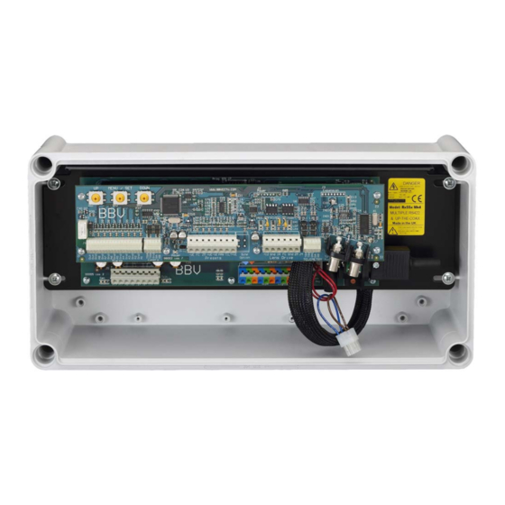
- Page 1 RX550 and RX450 Panasonic RS485 receivers Installation Guide Model Shown: RX550 Building Block Video Ltd. 17 Apex Park, Diplocks Industrial Estate, Hailsham, East Sussex, BN27 3JU UK. Tel: +44(0)1323 842727 Fax: +44(0)1323 842728 Support: +44(0)1323 444600 www.bbvcctv.com...
-
Page 2: Pre-Installation Checks And Safety Procedures
1. PRE-INSTALLATION CHECKS AND SAFETY PROCEDURES UNPACKING Check Packaging - Upon taking delivery of the unit, inspect the packaging for signs of damage. If damage has occurred, advise the carriers and/or the suppliers immediately. Check Contents - Upon taking delivery of the unit, unpack the receiver carefully and check that all the items are present and correct. - Page 3 Overloading - Do not overload outlets and extension cords, as this can result in fire or electric shock. Object and Liquid Entry - Never push objects of any kind into the unit, as they may touch dangerous voltage points or short out parts that could result in fire or electric shock. Never spill liquid of any kind on or inside the unit.
- Page 4 GENERAL The Rx450 is designed to control 24Vac/230Vac operated pan/tilt mechanisms and the Rx550 is designed to control 24Vdc high/variable speed heads from a Panasonic RS485 telemetry control system. The receivers can be connected using either a daisy chained or star wired RS485 network depending upon the model of Panasonic controller used.
- Page 5 Video launch amplifier provided with cable length adjustment 12Vdc/500mA camera power provided. Colour coded outlets – live, neutral, earth and low voltage. Telemetry Signal 2 or 4 wire Panasonic RS485 Auto Iris Output Returns to original setting 15 seconds after key release. Level programmable from controller.
- Page 6 Video launch amplifier provided with cable length adjustment 12Vdc/500mA camera power provided. Colour coded outlets – live, neutral, earth and low voltage. Telemetry Signal 2 or 4 wire Panasonic RS485 Auto Iris Output Returns to original setting 15 seconds after key release. Level programmable from controller.
-
Page 7: Cable Connection Method
CABLE CONNECTION METHOD Cage clamp connectors The cage clamp connector is a simple-to-use method of attaching cables to PCBs quickly and easily. Prepare cables as follows: 1. Use only cable between 0.08 and 2.5 mm² 2. Strip the cable to a length of 5 to 6 mm (0.23 in) The correct method of attachment is as follows: 1. - Page 8 BBV RX450 - RX550 SERIES RECEIVER SUPPLY OPTIONS AND LINKS 230Vac IN - 230Vac OUT 110Vac IN - 110Vac OUT (Factory fitted option) Supply IN J3 aux link Supply IN J3 aux link BLUE BLUE BROWN BROWN 230Vac IN - 24Vac OUT...
-
Page 9: Installation
3. INSTALLATION RIGHT As shipped, the auxiliary and head drive outputs are set to 24Vac with the RED linked plug fitted to J3. To set the outputs to the same voltage as the receiver supply remove the red plug and replace with the plug with the BROWN and BLUE links as shown above. Rx450AC Rx550DC MK3 Installation Manual - V19 30Sep05.doc Page 9/28... - Page 10 NEUTRAL As shipped, the auxiliary outputs are set to 24Vac with the RED linked plug fitted to J3. To set the outputs to the same voltage as the receiver supply remove the red plug and replace with the plug with the BROWN and BLUE links as shown above. Rx450AC Rx550DC MK3 Installation Manual - V19 30Sep05.doc Page 10/28...
- Page 11 Table showing the polarity of pan/tilt head and lens outputs. Use in conjunction with head/lens manual to determine correct wiring. Ensure that the pan/tilt motor and brake wiring is correct and NOT crossed before powering up the receiver as damage could be caused. Note, that the lens outputs can be reversed from within the OPTIONS menu of the receiver menu.
-
Page 12: Example Connection Diagrams
4 WIRE Spur to Coax - To WJ-FS616 provide isolation screen FS616 Rx550 RS485 telemetry cable 2 WIRE screen Camera 1 I/ WJ-FS616 Multiplexer 230Vac Supply Single Rx550 with WJ-FS616 Rx450AC Rx550DC MK3 Installation Manual - V19 30Sep05.doc Page 12/28... - Page 13 Rx550 DOME 4 WIRE RS485 Telemetry Connection details screen screen screen FS616 Rx550 Rx550 DOME WJ-FS616 Multiplexer 2 WIRE screen screen screen Multiple Rx550 and RS485 controlled domes with WJ-FS616 Rx450AC Rx550DC MK3 Installation Manual - V19 30Sep05.doc Page 13/28...
- Page 14 Multiple Rx550 and up-the-coax controlled dome with WJ-FS616 Notes: When using a daisy chained RS485 system, the stubs must be kept as short as possible and no longer than 25cm. Intermittent and/or sluggish control can be the result of excessive stub lengths.
- Page 15 The following diagram shows cable Connection details connections for 4 wire mode. Rx550 Ensure that the receiver is set to the same baud rate as the controller. The receiver default setting is 9600 baud. The receiver baud rate is set on the BAUD RATE line of MAIN/RECEIVER/COMMUNICATIONS/MENU.
-
Page 16: Diagnostic Aids
Use SW1 (UP) or SW3 (DOWN) to move to TELEM DATA and press SW2 (MENU/SET) to choose either 2 WIRE or 4 WIRE as required. g) DELAY TIME can be left at OFF. Please refer to Panasonic equipment manual before adjusting this. -
Page 17: Cable Length Compensation
CABLE LENGTH COMPENSATION The receiver incorporates a remotely adjustable high quality launch amplifier to compensate for video cable losses over extended cable distances. The gain of the launch amplifier can be adjusted in the receiver LAUNCH AMP GAIN line of the MAIN/RECEIVER/OPTIONS menu. The gain can be varied from 0 - 255, the higher the number, the higher the gain. -
Page 18: Programming The Receiver
The exact operation will vary depending upon the model of Panasonic controller used however for the FS616 multiplexer press and hold the SETUP/ESC key then tap the camera number corresponding to the receiver. - Page 19 RECEIVER MENU STRUCTURE/RX550 VERSION SHOWN RX550DC MAIN MENU CAMERA RECEIVER Notes: Navigation: UP and DOWN to move selected line. LEFT or RIGHT is used to either select the submenu or cycle options. NEXT will display the next screen of multi-screen menus and BACK will display the previous screen.
- Page 20 BAUD RATE 9600 RS485 baud rate 1200/2400/4800/9600/19200 TELEM DATA 4 WIRE 2 WIRE/4 WIRE RS485 network from Panasonic controller DELAY TIME TX/RX delay 10/20/40/100mS/OFF for use with RF links etc MENU UNLOCK LOCKED Must be set to UNLOCKED to allow setting of above...
-
Page 21: Display Options
1-10. Position of status on screen, 1=top,10=bottom ON POWER UP NO ACTION Select either PRESET 1/RANDOM PAN/PATROL 1/NO ACTION CAMERA TYPE 4 WIRE Choose 2/4 wire comms if using Panasonic camera SIN COS IP NOT FITTED FITTED using continuous rotation pan with sin/cos pots BACK RETURN... -
Page 22: Reset Receiver
OPTIONS menu and toggle between REVERSE/NORMAL FOCUS NEAR FOCUS FAR IRIS OPEN IRIS CLOSE WASH WIPE LIGHTS AUTOPAN AUTOPAN does nothing with RX550 RETURN RETURN to TEST MENU Rx450AC Rx550DC MK3 Installation Manual - V19 30Sep05.doc Page 22/28... - Page 23 MOTOR OPTIONS RX550DC MOTOR OPTIONS These settings allow the receiver to be tailored to different pan/tilt motors. The MIN/MAX values MAX PAN set the minimum and maximum speeds during manual control MIN PAN 255 is maximum speed and 0 is minimum MAX TILT If the minimum is too low, the head may stall at low MIN TILT...
- Page 24 Multiple functions can be controlled simultaneously. E.g. Pan Left and Tilt Down. To move the pan/tilt head to a preset position, refer to the Panasonic controller manual. The receiver supports preset 1 – 64. If this preset has been programmed, the head/lens will move to show the preset position.
- Page 25 LIGHTS: The lights auxiliary output is turned on/off with this line. If WIPE/LIGHTS/AP is set to YES in the DISPLAY OPTIONS menu from the OPTIONS 2 menu then a * symbol is displayed whilst the lights are on. WASH/WIPE: The WIPE auxiliary output is turned on and the WASH auxiliary output is activated for the time set in the OPTIONS menu.
- Page 26 Blank for your notes Rx450AC Rx550DC MK3 Installation Manual - V19 30Sep05.doc Page 26/28...
- Page 27 Blank for your notes Rx450AC Rx550DC MK3 Installation Manual - V19 30Sep05.doc Page 27/28...
-
Page 28: Product Description
BBV coax PELCO P/D RS485, VCL RS485, PHILIPS RS485 (OPTIONAL BI-PHASE INPUT), DENNARD RS485 RX450/550 PANASONIC RS485 Protocol only version of RX45X/55X. 8 * RS485 output with option of protocol conversion. STARCARD STARCARD/CONVERTER TxLD (bidirectional RS422-RS232 converter) ACCESSORIES 98005 (bidirectional 20mA-RS232 converter) Rx450AC Rx550DC MK3 Installation Manual - V19 30Sep05.doc...