Garmin GTX 320 Installation Manual
Garmin gtx 320/320a transponder installation manual
Hide thumbs
Also See for GTX 320:
- Pilot's manual (4 pages) ,
- Pilot's manual (8 pages) ,
- Installation manual (37 pages)
Table of Contents
Advertisement
Advertisement
Table of Contents

Related Manuals for Garmin GTX 320


Summary of Contents for Garmin GTX 320
- Page 1 GTX 320/320A Transponder Installation Manual 190-00133-01 July, 2006 Revision M...
- Page 2 Garmin. Garmin hereby grants permission to download a single copy of this manual and of any revision to this manual onto a hard drive or other electronic...
- Page 3 California to cause cancer, birth defects, or reproductive harm. This Notice is being provided in accordance with California's Proposition 65. If you have any questions or would like additional information, please refer site www.garmin.com/prop65. GTX 320/320A Installation Manual Page i 190-00133-01 Rev M...
-
Page 4: Table Of Contents
PAGE APPENDIX A, CERTIFICATION DOCUMENTS................. A-1 A.1 Continued Airworthiness........................A-1 A.2 Environmental Qualification Form - (GTX 320) ................A-4 A.3 Environmental Qualification Form - (GTX 320A) ................A-6 APPENDIX B, STC PERMISSION-GTX 320 ..................B-1 APPENDIX C, ASSEMBLY AND INSTALLATION DRAWINGS ............C-1... - Page 5 PAGE 2-1 BNC Connector Assembly Drawing ....................2-4 2-2 25 Pin D-Sub Connector Drawing..................... 2-7 3-1 Transponder Front Panel (GTX 320 Shown) ..................3-1 C-1 GTX 320/320A Outline Drawing......................C-3 C-2 GTX 320/320A Connector/Rack Kit Assembly Drawing..............C-5 C-3 GTX 320/320A Recommended Panel Cutout Dimensions ...............C-7 C-4 GTX 320/320A Interconnect Wiring Diagram..................C-9...
- Page 6 GTX 320 HARDWARE MOD LEVEL HISTORY The following table identifies hardware modification (Mod) Levels for the GTX 320 Transponder. Mod Levels are listed with the associated service bulletin number, service bulletin date, and the purpose of the modification. The table is current at the time of publication of this manual (see date on front cover) and is subject to change without notice.
-
Page 7: General Description
Receiving ground radar interrogations at 1030 MHz, it transmits a coded response of pulses to ground-based radar on a frequency of 1090 MHz. As with other Mode A/Mode C transponders, the GTX 320/320A replies with any one of 4,096 codes, which differ in the position and number of pulses transmitted. By “replying” to ground transmissions, your GTX 320/320A enables ATC computers to display aircraft identification, altitude and ground speed on ATC radar screens. -
Page 8: Equipment Available
Table 1-4 Available Configurations Item Garmin P/N Garmin GTX 320 Transponder 010-00135-00 Garmin GTX 320A Transponder 010-00247-00 Garmin GTX 320 Transponder includes Garmin installation kit, 010-00135-03 P/N 010-10161-00 Garmin GTX 320A Transponder includes Garmin installation kit, 010-00247-02 P/N 010-10161-01 Page 1-2... -
Page 9: Additional Equipment Required
Installation Approval The conditions and tests required for TSO approval of the GTX 320/320A Transponder and antenna are minimum performance standards. It is the responsibility of the installer to determine that the aircraft installation standards for a specific type or class of aircraft are in compliance with all applicable TSO requirements. -
Page 10: Limited Warranty
Garmin retains the exclusive right to repair or replace the unit or software or offer a full refund of the purchase price at its sole discretion. SUCH REMEDY SHALL BE YOUR SOLE AND EXCLUSIVE REMEDY FOR ANY BREACH OF WARRANTY. -
Page 11: Installation Overview
If the unit is damaged, notify the carrier and file a claim. To justify a claim, save the original shipping container and all packing materials. Do not return the unit to Garmin until the carrier has authorized the claim. - Page 12 4. Obtain FAA Advisory Circular AC-183C and select (and contact) a DER from the roster of individuals identified there under. 5. Contact an aviation industry organization such as the Aircraft Electronics Association and request their assistance. Page 2-2 GTX 320/320A Installation Manual Rev M 190-00133-01...
- Page 13 M17/128 (RG-400) cable. The completed cable including connectors must introduce no more than 1.5 dB attenuation at 1 GHz. Instructions for installing the item 6 are shown in Figure 2-1 and detailed in the following steps A-G. GTX 320/320A Installation Manual Page 2-3 190-00133-01...
- Page 14 Heat the outside of the connector sleeve and at the same time apply solder between the braid and the sleeve. Continue to apply heat until the solder flows evenly. Install 50 Matching Bushing. Insert connector cap and tack solder in two places. Page 2-4 GTX 320/320A Installation Manual Rev M 190-00133-01...
-
Page 15: Gtx 320/320A Installation
All wiring must be in accordance with FAA AC 43.13-2A. GTX 320 units that are at Mod Level 1 must use the Mod Level 1 Rack Assembly. After Mod Level 1, GTX 320 installations are 0.170" (4.31 mm) deeper in the panel. -
Page 16: Electrical Connections
NOTES 1. Insertion/extraction tools from ITT Cannon are all plastic; others are plastic with metal tip. 2. Non-Garmin part numbers shown are not maintained by Garmin and consequently are subject to change without notice. 3. Alternate contacts for 18 AWG wire: As an alternative to the Positronic contacts listed (and provided in the installation kit), the installer may use contacts made by ITT Cannon under P/N 031-1007-001. - Page 17 Switched Power Output Aircraft Power (+11 to +33 VDC) External Standby External Suppression (Suppress I/O-GTX 320A) Altitude D4 Not Used Not Used Not Used Not Used 28 V Lighting 14 V Lighting Ground GTX 320/320A Installation Manual Page 2-7 190-00133-01 Rev M...
-
Page 18: Check Existing Coax And Antenna Before Using A Gtx320/320A Adapter
2.7 Installation Using Existing Narco AT 150 Installation Rack The GTX 320 and GTX 320A can be used with an existing NARCO AT 150 Installation Rack by using the NARCO AT 150 Installation Adapter (P/N 011-00292-00). See figure B6 for the NARCO AT 150 Adapter assembly drawing. -
Page 19: Installation Using Existing Bendix/King 76A/78A Installation Rack
2.8 Installation Using Existing Bendix/King KT 76A/78A Installation Rack The GTX 320 and GTX 320A can be used with an existing Bendix/King KT 76A/78A installation rack by using the KT 76A/78A Installation Adapter (P/N 011-00289-00). See figure B7 for the Bendix/King KT 76A/78A Adapter assembly drawing. - Page 20 Blank Page Page 2-10 GTX 320/320A Installation Manual Rev M 190-00133-01...
-
Page 21: Post Installation Configuration & Checkout Procedure
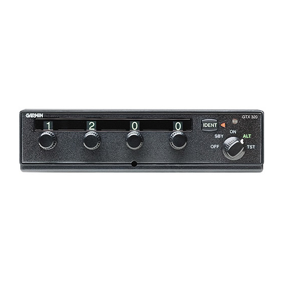
At the present time, you do not need an individual license to operate the GTX 320/320A aboard your private aircraft in many circumstances. To find out the specific details on whether you are exempt from licensing, please see FCC Fact Sheet PR 5000 or contact the FCC at (800)-322-1117. - Page 22 3.2.1 Function Selection Switches The function selector switch is a five position rotary switch. The five positions are: Turns off all power to the GTX 320/320A. Turns the transponder on, but when in SBY the transponder will not reply to any interrogations from the ground radar system.
- Page 23 20 seconds identifying your transponder return from other aircraft on the controller’s scope. 3.2.4 Reply Light The reply light will blink each time the transponder replies to ground interrogation. The reply light also remains lit during the IDENT time interval. GTX 320/320A Installation Manual Page 3-3 190-00133-01 Rev M...
- Page 24 Blank Page Page 3-4 GTX 320/320A Installation Manual Rev M 190-00133-01...
-
Page 25: Appendix A, Certification Documents
It is the applicant’s responsibility to determine the suitability of the documents for the ICA. Following is a suggested ICA for a Garmin GTX 320/320A unit installation. Some of the checklist items do not apply, in which case they should be marked “N/A” (Not Applicable). - Page 26 Refer to the GTX 320/320A Pilot’s Guide. Servicing Information Maintenance Instructions Maintenance of the GTX 320/320A is ‘on condition’ only. Periodic maintenance is not required. Refer to the GTX 320 and the 320A Series Maintenance Manuals. Troubleshooting Information Refer to the GTX 320 and the GTX 320A Maintenance Manuals.
- Page 27 43.9. This entry records the major alteration and identifies the original ICA location (e.g., Block 8 of FAA Form 337, dated ______) along with a statement that the ICA is now part of the aircraft’s inspection/maintenance requirements. GTX 320/320A Installation Manual Page A-3 190-00133-01...
-
Page 28: Environmental Qualification Form (Gtx 320)
Environmental Qualification Form (GTX 320) NOMENCLATURE: GTX 320 Airborne ATC Transponder Equipment TYPE/MODEL/PART NO.: 010-00135-00/10 TSO - C74c Class 1A MANUFACTURER'S SPECIFICATION AND/OR OTHER APPLICABLE SPECIFICATION: 004-00042-00 MANUFACTURER: Garmin International ADDRESS: 1200 E 151st St, Olathe, Kansas 66062 Table A-1 GTX 320 EQF Table... - Page 29 Table A-1 GTX 320 EQF Table (continued) Conditions RTCA DO- Description of Conducted Tests 160C Section Audio Frequency 18.0 Equipment tested to Category B Susceptibility Induced Signal 19.0 Equipment tested to Category A Susceptibility Radio Frequency 20.0 Equipment tested to Category U...
-
Page 30: Environmental Qualification Form (Gtx 320A)
11.0 Equipment identified as Category X, no test required Sand and Dust 12.0 Equipment identified as Category X, no test required Fungus 13.0 Equipment identified as Category X, no test required Page A-6 GTX 320/320A Installation Manual Rev M 190-00133-01... - Page 31 Equipment identified as Category X, no test required Icing 24.0 Equipment identified as Category X, no test required Electrostatic Discharge 25.0 Equipment identified as Category X, no test required Remarks- None GTX 320/320A Installation Manual Page A-7 190-00133-01 Rev M...
- Page 32 Blank Page Page A-8 GTX 320/320A Installation Manual Rev M 190-00133-01...
- Page 33 APPENDIX B STC PERMISSION Consistent with N8110.69 or Order 8110.4, Aviation Authority approved installations are hereby granted permission to use STC # SA00642WI data to modify aircraft. GTX 320/320A Installation Manual Page B-1 190-00133-01 Rev M...
- Page 34 Page B-2 GTX 320/320A Installation Manual Rev M 190-00133-01...
-
Page 35: Appendix C, Assembly And Installation Drawings
ASSEMBLY AND INSTALLATION DRAWINGS GENERAL This section contains the following installation drawings: C-1, GTX 320/320A Outline Drawing C-2, GTX 320/320A Connector/Rack Kit Assembly Drawing C-3, GTX 320/320A Recommended Panel Cutout Dimensions C-4, GTX 320/320A Interconnect Wiring Diagram C-5, Dual Transponder Interconnect Wiring Diagram... - Page 36 Blank Page Page C-2 GTX 320/320A Installation Manual Rev M 190-00133-01...