
Related Manuals for Vermont Castings Deviant Encore 0028


Summary of Contents for Vermont Castings Deviant Encore 0028
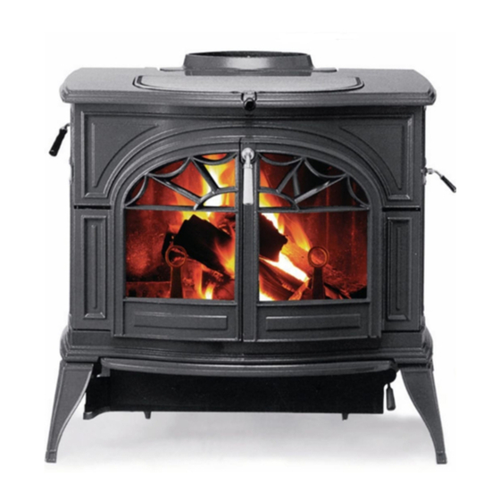
- Page 1 F o r t h e V e r m o n t C a s t i n g s F o r t h e V e r m o n t C a s t i n g s Defiant Encore Models: Defiant Encore Models: #0028...
-
Page 2: Defiant Encore Design Changes
Defiant Encore Design Changes The Defiant Encore damper was modified in October 1986 to provide a cast wedge shaped stop to prevent the damper from striking or resting on the catalytic package when operating the stove in the updraft mode. The torsion bar slide area in the centre of the damper was widened to preclude torsion bar binding when opening and closing the damper. - Page 3 DEFIANT ENCORE 1. Exploded View Parts Illustrations 2. Parts List 3. Drill and Tap Illustrations 4. Drill and Tap Guide 5. Individual Part Replacement/Repair Procedures 6. Complete Disassembly Procedure 7. Complete Gasketing Procedure 8. Complete Assembly Procedure 9. Appendix...
- Page 5 DEFIANT ENCORE 0028 / 2140 DEFIANT ENCORE MODEL #: FEATURES: MODEL #0028 MANUFACTURED 7/11/86 THRU 4/25/90 WITH A GEISSER TESTING LAB. LABEL MODEL #2140 MAUNFACTURED 5/17/90 THRU 11/5/91 WITH A WARNOCK HERSEY TESTING LABEL CATALYST ACCESS IN THE BACK OF THE STOVE / DOUBLE PANE OF GLASS IN EACH DOOR * denotes dead product - not available ITEM # PART # DESCRIPTION...
- Page 7 DEFIANT ENCORE HARDWARE LIST MODEL #: 0028 / 2140 DEFIANT ENCORE FEATURES: MODEL #0028 MANUFACTURED 7/11/86 THRU 4/25/90 WITH A GEISSER TESTING LAB. LABEL MODEL #2140 MAUNFACTURED 5/17/90 THRU 11/5/91 WITH A WARNOCK HERSEY TESTING LABEL CATALYST ACCESS IN THE BACK OF THE STOVE / DOUBLE PANE OF GLASS IN EACH DOOR * denotes dead product - not available ITEM # PART # DESCRIPTION...
- Page 8 Shell Parts - Defiant Encore Model #0028 / 2140 Part Name Classic Sand Blue Midn't Ant Grn Ant Brn Gray (130) (131) (132) (133) (134) (138) (139) (136) Flue Collar 1304280 2324280* 1324280 1334280 1344280 Ash Lip 1307406 2327406* 1327406 1337406 1347406 1307427...
- Page 9 Defiant Encore Drill and Tap Guide Drill Depth Tap Size Tap Type 13 / 64" Thru 1 / 4" - 20 Taper # 22 1 / 2" 10 - 24 Bottoming # 22 3 / 8" 10 - 24 Bottoming # 22 Thru 10 - 24...
-
Page 18: Tools Required
Defiant Encore – Individual Repair Section GENERAL: The manner in which to proceed with the most repairs to this stove will be obvious to the competent mechanic. Individual parts replacement and adjustment procedures are covered in the Disassembly and Assembly sections of this manual. Cleanings, re-gasketing and/or cementing procedures are covered in the Cementing and Re-Gasketing sections of this manual. - Page 19 STEP 5: Remove the old cable from either the air valve or thermostat jump ring. STEP 6: Fabricate a cable fishing tool from the 1/16” diameter X 36” gas welding rod as shown in figure R-1. Make the 2” bend and the ¼” loop on the opposite end of the rod on the same plane.
- Page 20 Replacing or Servicing the Damper Linkage Tools Required • Allen Wrench, 5/32” • Cold Chisel, ½” • Caulking Gun Frame • Hammer, Ball Peen, 12 oz. • Thermocement, 11 oz. tube • Safety Goggles STEP 1: Place the damper in the open or updraft position and remove the damper handle stub.
- Page 21 Replacing or Servicing the Upper Fireback and Damper Assembly (Also see note in Appendix) Tools Required • Ratchet Handle, 3/8” drive • Caulking Gun Frame • 7/16” Deepwell socket, 3/8” • Thermocement, 11 oz. tube • Cold Chisel, ½” drive •...
- Page 22 Replacing or Servicing Damper Tabs and Torsion Bar Clip Tools Required • Ratchet Handle, ¼” drive • 2” Extension, ¼” drive • 7/16” Socket, ¼” drive • Screwdriver, Phillips, # 2 tip • 7/16” Combination Wrench (box and open) STEP 1: Remove the flue collar.
- Page 23 STEP 6: Inspect the kaowool strips in the lower fireback and the bottom of the stove back. If the kaowool strips are compressed below the top edge of the inside ribs of either the lower fireback or the stove back, replace them. The kaowool strips when in place must provide a complete seal as well as a cushion for the refractory package.
- Page 24 Eliminating Air Leaks at the Fire Door Tools required • 7/16” Combination Wrench (box • Wire Brush • Rubber Mallet, 4 lbs. dead blow & open) • 9/16” Combination Wrench (box • 7/32” Allen Wrench & open) • Flat file, medium cut •...
- Page 25 Defiant Encore – Complete Disassembly Tools Required • 1-Drop cloth, 8”x 8” (minimum size) • 1-Pail electricians’ side cutting • 1-Pair of safety goggles pliers, 6” • 1-Putty knife • 1-Respirator, dust & mist • 1-Shop type vacuum cleaner with •...
- Page 26 Disassembly STEP 1: Lift out the griddle. Remove the ash pan and dump ashes in a safe container outdoors. Wash the ash pan and dry it. The ash pan will make a good container for screws, bolts, nuts, washers and small hardware items during the disassembly of the stove.
- Page 27 STEP 11: Remove the lower fireback, 2 each, ¼-20 x 1” hex head cap screws and 2 each, ¼” flat washers. Pry the fireback loose with a pinch bar from its bottom cement channel. STEP 12: Remove the stove back, 6 each, ¼-20 x 3/4” hex head cap screws and 6, each ¼”...
- Page 28 STEP 16: Remove the left air wear plate, 2 each, ¼-20x1” hex head cap screws. Chip away the cement at the joints and mating surfaces with a cold chisel and ball peen hammer. Drive the ½” cold chisel between the rear flange (extreme top and bottom) of the wear plate and the stove end and gently pry loose (see fig.
- Page 29 STEP 22: Remove the ash drop assembly. Remove the hairpin cotter from the upper end of the ash door clevis pin. Pull the ash door clevis pin down, disengaging the hinge. Remove the ash door assembly. Remove the flat ash grate. Turn the stove bottom over and remover, 4 each, ¼-20 x ¾” hex head cap screws and 4 each, ¼”...
- Page 30 STEP 29: Examine the combustion package assembly. Check the heat exchanger for distortion, loose spot welds, etc. Check the right and left heat deflectors for distortion. Check the refractory stainless steel cover for distortion. Replace any defective parts. Check the catalyst block for general deterioration.
- Page 31 7/32” Allen wrench. After thorough cleaning, pain the outside surface of the doors and hinge bosses at this time. Use Vermont Castings High Temperature Aerosol Stove Paint (black), part number 000-0031 and follow directions on the can.
- Page 32 Gasketing STEP 1: Remove the old gasketing paying particular attention to the place where a continuous gasket meets itself. STEP 2: Clean all gasket channels and grooves with a wire brush (hand or power). Remove any stubborn deposits of gasket cement with the appropriate size punch/drive pin or cold chisel.
- Page 33 Defiant Encore Gasket Requirements. Refer to the Gasket Illustration figure numbers. Top (Fig.1) Griddle opening, one place, 4”-Armaseal 5/16” diameter, cored, part # 120-3668. Ash Drop (Fig.2) Ash drop to bottom seal, one piece, both sides and back. 4’ Thermocord 5/16” diameter, 6 needle, part # 120-3588. Lower Fireback (Fig.3) Both sides to wear plates seal, two pieces, 8”...
- Page 34 Upper Fireback (Fig.4) Both sides to wear plates and lower fireback seal, 2 pieces, 18” each, thermocord, 5/16” diameter, 6 needle, part # 120-3588. Ash Door (Fig.5) Complete door to ash drop seal, 1 piece, 4’ thermocord, 3/8” diameter, 4 needle, part # 120-3589. Damper (Fig.6) Complete damper to upper fireback seal, 1 piece, 3.5’...
- Page 35 Catalyst Access Panel (Fig.9) Catalyst access panel to stove back seal, 1 piece, 3’6”, thermocord, 5/16” diameter, 6 needle, part # 120-3588. Right Door (Fig.10) Right door to stove front seal, 1 piece, 3’, thermocord, 5/16” diameter, 6 needle, part # 120-3588. Left Door (Fig.11) Left door to stove front and right door seal, 1 piece, 4’, thermocord, 5/16”...
- Page 36 Door Glass (Fig.12) Gasket #1 provides cushioning between the casting and the bottom of the glass panes, 1 piece, 9”, Interam 3M, flat, part # 120-3537. This gasket is applied with Tite Bond Glue or gasket adhesive. Gasket #2 provides cushioning between the outer glass pane and the castings in addition to a seal, 1 piece, 3’, 2”...
- Page 37 Defiant Encore 0028/2140 Assembly Service Manual General: All parts were carefully inspected and cleaned to bare metal or replaced during the disassembly process. Assembly may now begin. To achieve a properly functioning, air tight stove, 6 each, 11 oz. tubes of thermocement, part number 120-6125 are required.
- Page 38 STEP 4: Place the ash lip on the stove bottom and secure with 2 each, socket flat head machine screws (¼-20x ½”). STEP 5: Assemble the primary air regulator system. Place the primary air frame face down on a flat surface (drilled bosses up). Thread the primary air rod through the drilling in the bottom of the air valve and just start it into the left top (hinge) drilling of the frame.
- Page 39 STEP 8: Cement all channels, flanges and mating surfaces indicated in Figure C-2. Do not allow any cement to contact the thermostat cable. Place the primary air tube cover plate in position on the stove bottom and secure with 3 each, Phillips flat head machine screws (¼-20 x 2”). Fig.
- Page 40 STEP 11 Cont.: Place the left stove end firmly into its mating channel in the stove front, swing the back of the end onto the stove bottom so that the drilling in the inside bottom flange of the end aligns with the tapped hole in the stove bottom.
- Page 41 STEP 15: Cement the mating surfaces on the reverse side of the left air/wear plate as indicated in Figure C-9. Insert the front mating surface of the left air/wear plate against the left end of the front air manifold and the front of the left stove end at a 30 degree angle.
- Page 42 STEP 18: Assemble the combustion package assembly. If the refractory package and/or the catalyst access panel (refractory) are being replaced, it may be necessary to cut and fit the access panel. Use the serrated edge kitchen knife and achieve a good tight all around fit. Place the heat exchanger into the front opening of the refractory assembly--tape in place with masking tape.
- Page 43 STEP 20 Cont: When the slack is out of the cable, tighten the set screw on the air valve. Push the thermostat shaft from inside the stove until stiff resistance is felt from the friction spring, slip the thermostat Fig. C-11 handle stub on the end of the shaft and push the handle stub Thermostat tight against the outside of the right stove end.
- Page 44 STEP 23: Install the lower fireback. Cut 2 each, 7” strips of ¾” square kaowool. Place the kaowool strips between the outer ribs of the reverse side of the fireback (left and right) as shown in Fig.A-7. Place the lower fireback into position against the combustion package assembly, aligning the drillings in the lower fireback with the tapped holes in the right and left air/wear plates.
- Page 45 STEP 26 Cont: the damper handle rod. Insert the long end of the damper handle rod through its drilling in the left stove end. Insert the shot end of the damper actuator link. Align the linkage properly and check operation for binding and/or stoppage.
- Page 46 STEP 31 Cont: o’clock positions respectively and re-tighten the lock nuts. Insert the double bent end of the secondary air link through the hole in the tab end of the thermostat coil. Insert the single bent end of the secondary air link through the hole in the tab on the secondary air flap.
- Page 47 STEP 33 Cont.: that the handle turns without binding. Tighten the set screw in the pawl. Thread the hex toplock jam nut onto the handle shaft and tighten it against the pawl. With your 7/16” wrench, tighten the 3 cap screws attaching the split half hinge to the ash drop slightly (just past finger tight).
- Page 48 Fig. A-10 Ash Door Seal Test STEP 35: Install the ash pan bracket on the ash door. Secure with 2 each, hex head cap screws (¼-20x ½”) and 4 each, (2 per cap screw) standard flat washers (¼”). Tighten the cap screws finger tight. Close and open the ash door. If the bracket contacts the ash drop, adjust the bracket by tapping it left or right as required so that no metal to metal contact occurs when opening and closing the ash door.
- Page 49 STEP 40: Paint the stove. Use Vermont Castings High Temperature Stove Paint (black), part # 000-0031. Follow directions printed on the can and paint the entire outside of the stove.
- Page 50 STEP 41 Cont: and when turned counter clockwise against its stop, should pull both doors snugly against the stove front and each other. If the doors are loose when the handle tab is fully engaged, open the right door and turn the door handle 360 degrees (one full turn) counterclockwise.
- Page 51 STEP 42: Assemble and install the griddle. Place the griddle quadrants on the underside of the griddle and secure with 2 each, hex head cap screws (¼- 20x½”). Install the griddle handle assembly and secure with 1 each, hex nut (10-24) and 1 each #10 washer. Install the griddle on the stove and tap gently around its perimeter with a rubber mallet to seat the gasket.
- Page 52 APPENDIX #1 SUGGESTED FIX FOR BENT DAMPER CLIPS ENCORE 0028/2140 DIAGRAM PART QUANTITY DESCRIPTION NUMBER 160-1036 Torsion Bar Clip 120-2474 ¼” Flat Washer 120-1310 ¼-20 Plain Nut 120-0446 ¼-20 x 1¼” Socket SS...
-
Page 53: General Checklist
APPENDIX #2 YEARLY MAINTENANCE SUGGESTIONS The 0028 and 2140 Defiant Encore is a sophisticated combustion machine, and regular “fine tuning” will give you the full benefits of its operating potential. GENERAL CHECKLIST • Inspect the chimney for blockage such as squirrels, nests, branches, etc. •... - Page 54 element ends to draw the element from the stove. If the honeycomb is clogged, take the element outside for cleaning. Blow gently through the honeycomb. Inspect the element. Although small hairline cracks will not affect performance, the element should essentially be intact. If elements are broken or missing, the catalyst should be replaced.
-
Page 55: Clean The Glass
CHECK THE DAMPER The Encore’s damper is designed to snap into a locked position. When closing the damper, push the handle past the point at which you feel resistance until it snaps into the locked position. • Place several pieces of note paper along the top and bottom of the damper and lock the damper.