Table of Contents
Advertisement
Advertisement
Table of Contents

Related Manuals for Jet JWBS-14CS


Summary of Contents for Jet JWBS-14CS
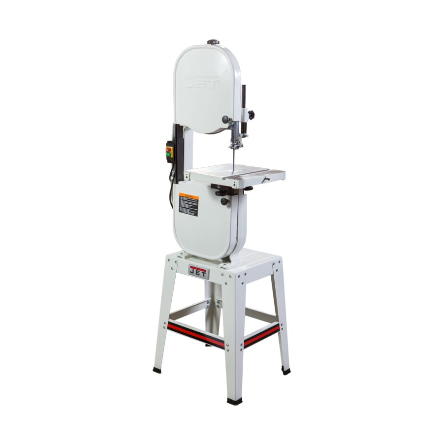
- Page 1 This Manual is Bookmarked Operating Instructions and Parts Manual 14-inch Woodworking Band Saw Models: JWBS-14OS, JWBS-14CS WMH TOOL GROUP 2420 Vantage Drive Elgin, Illinois 60123 Part No. M-708115 Ph.: 800-274-6848 Revision C 9/05 www.wmhtoolgroup.com Copyright © WMH Tool Group...
-
Page 2: Warranty And Service
This manual has been prepared for the owner and operators of a JET JWBS-14 Band Saw. Its purpose, aside from machine operation, is to promote safety using accepted operating and maintenance procedures. To obtain maximum life and efficiency from your band saw and to aid in using it safely, please read this manual thoroughly and follow the instructions carefully. -
Page 3: Table Of Contents
Closed Stand Assembly (JWBS-14CS Band Saw)...27 Closed Stand Assembly (JWBS14-CS Band Saw)...28 Open Stand Assembly (JWBS-14OS Band Saw) ...29 Open Stand Assembly (JWBS-14OS Band Saw) ...30 Electrical Connections – 115 volt (JWBS-14CS/OS Band Saw) ...31 Electrical Connections – 230 volt (JWBS-14CS/OS Band Saw) ...32... -
Page 4: Warning
4. This band saw is designed and intended for use by properly trained and experienced personnel only. If you are not familiar with the proper and safe operation of a band saw, do not use until proper training and knowledge have been obtained. -
Page 5: Save These Instructions
blahblahblah 21. Make your workshop child proof with padlocks, master switches or by removing starter keys. 22. Give your work undivided attention. Looking around, carrying on a conversation and “horse-play” are careless acts that can result in serious injury. 23. Maintain a balanced stance at all times so that you do not fall or lean against the blade or other moving parts. -
Page 6: Introduction
This manual is provided by JET covering the safe operation and maintenance procedures for a Model JWBS-14 Band Saw. This manual contains instructions on installation, safety precautions, general operating procedures, maintenance instructions and parts breakdown. This machine has been designed and constructed to provide years of trouble free operation if used in accordance with instructions set forth in this manual. -
Page 7: Unpacking - Jwbs-14Os
3 – M5x12 pan head screws (approx. 1/2”) 6 – M5 flat washers 3 – M5 hex nuts E. Trunnion Support Bracket to Saw Body 2 – M8x30 hex cap screws (approx. 1-1/4") 2 – M8 lock washers 1 – M8x80 hex cap screw (for table stop - approx. -
Page 8: Unpacking - Jwbs-14Cs
Unpacking – JWBS-14CS Open both shipping containers and check for shipping damage. Report any damage immediately to your distributor and shipping agent. Read the instruction manual thoroughly for assembly, maintenance and safety instructions. Contents of the Shipping Container Container One:... -
Page 9: Assembly Of Jwbs-14Os
Failure to comply may cause serious injury! 4. With the aid of a second person, lift the saw body out of the shipping container and place onto the stand top. Be sure front of saw (with JET logo) faces stand front (JET logo). - Page 10 7. Place motor over rubber grommets and fasten to stand top with four hex cap screws, eight flat washers, washers, and four hex nuts, as shown in item C, page 7. See Figure 4. The arrangement of these fasteners is shown in Figure 5.
- Page 11 14. To mount table, remove table insert and table pin (see Figure 11). Orient the table so that the saw blade will pass through the slot in the table and into the center opening. Continue holding up the table, and turn the...
-
Page 12: Assembly Of Jwbs-14Cs
Failure to comply may cause serious injury! 3. With the aid of a second person, lift the saw body out of the shipping container and place onto stand top. Be sure front of saw (with JET logo) faces stand front (JET logo). - Page 13 1/2" deflection (Figure 16). 10. Screw the two small knobs (Figure 17) into the threaded holes in the saw body. Slide the pulley cover down over the knobs, and tighten the knobs. 11. Attach trunnion support bracket to saw body...
-
Page 14: Grounding Instructions
13. To mount the table, remove pin and insert from the table (Figure 19). 14. Orient the table so the saw blade will pass through the slot in the table and into the center opening. Continue holding up the table, and rotate the table so the two screws... -
Page 15: 115 Volt Operation
The band saw must comply with all local and national codes after the 230 volt plug is installed. 4. The band saw with a 230 volt plug should only be connected to an outlet having the same configuration (Figure 24). No adapter is available or should be used with the 230 volt plug. -
Page 16: Extension Cords
Make sure the cord is in good condition, and heavy enough to carry the current your band saw will draw. An undersized cord will cause a drop in line voltage, resulting in loss of power and overheating. Figure 25 shows the correct size to use depending on cord length and the ampere rating on your machine’s nameplate. -
Page 17: Changing Blades
90 degrees with the blade. If necessary, adjust scale pointer to zero. Changing Blades Blade teeth are sharp! Use care when handling the saw blade. Failure to comply may cause serious injury. Disconnect machine from power source. Loosen blade tension by turning the tension knob counterclockwise (Figure 28). -
Page 18: Adjusting Blade Tracking
As you become more experienced with the saw, you may find it necessary to change the blade tension from the initial setting. Changes in blade width and the type of material being cut will have an effect on blade tension. -
Page 19: Adjusting Blade Guide And Blade Support Bearing
Adjusting Blade Guide and Blade Support Bearing Blade guard removed for picture clarity. Never operate the band saw without all guards in place and in working order. Disconnect machine from power source. Blade must already be tensioned and tracking properly. - Page 20 Notice the bearing holder on the shaft is eccentric. Index the bearing shaft to another position and slide it back in, making sure the flange on the thumb screw (H, Figure 31) properly seats into the groove of the bearing shaft.
-
Page 21: Troubleshooting Jwbs-14Cs/Os Band Saw
Troubleshooting JWBS-14CS/OS Band Saw Trouble Probable Cause Saw unplugged. Saw stops or will not Fuse blown, or circuit breaker tripped. start. Cord damaged. Table stop not adjusted correctly. Does not make accurate 45 or 90 Angle pointer not set accurately. -
Page 22: Optional Accessories
Optional Accessories 708114 Three speed kit for JWBS-14CS Produces speeds of 965, 1470, and 2465 SPFM. Includes four step motor pulley, intermediate pulley, V-belts, fasteners, and mounting instructions with parts list. 708718 JRF-14 Rip Fence Assembly Includes guide bars, rip fence assembly, fasteners, and mounting instructions with parts list. -
Page 23: Replacement Parts
Blade Width (in.) Premium alloy Premium alloy Premium alloy Premium alloy Premium alloy Premium alloy Premium alloy Premium alloy Silicon steel 3/16 Silicon steel Silicon steel Silicon steel Silicon steel Silicon steel Silicon steel Silicon steel Silicon steel 3/16 Silicon steel Silicon steel Silicon steel Silicon steel... -
Page 24: Body Assembly (Jwbs-14Cs/Os Band Saw)
Body Assembly (JWBS-14CS/OS Band Saw) Index No. Part No. 1...150100AW ... Upper Arm Frame ..1 2...150037W ... Table ..1 3...100038... Table Pin ..1 4...708719... Guide Block ..4 5...150005A ... Upper Support Bracket Post..1 6...150006A ... -
Page 25: Body Assembly (Jwbs-14Cs/Os Band Saw)
Body Assembly (JWBS-14CS/OS Band Saw) Index No. Part No. Description 59 ...995001... Power Cord (Switch To Motor) ..1 60 ...995002... Power Cord (Switch To Power Soure)..1 61 ...990814... Self Tapping Screw... M3.5x19 ... 2 62 ...TS-1550021 ... Flat Washer ... M4 ... 2 63 ...TS-1533042 ... -
Page 26: Body Assembly (Jwbs-14Cs/Os Band Saw)
Body Assembly (JWBS-14CS/OS Band Saw) -
Page 27: Closed Stand Assembly (Jwbs-14Cs Band Saw)
Closed Stand Assembly (JWBS-14CS Band Saw) Index No. Part No. 1...150501W ... Stand..1 2...150502W ... Door ..1 3...150503... Door Latch Assembly..1 4...WBS14CS-04... Washer..2 5...WBS14CS-05... Pan Head Screw... M4x5 ... 2 6...PG-M02 ... JET Plaque..1 7...TS-1533031 ... -
Page 28: Closed Stand Assembly (Jwbs14-Cs Band Saw)
Closed Stand Assembly (JWBS14-CS Band Saw) -
Page 29: Open Stand Assembly (Jwbs-14Os Band Saw)
Open Stand Assembly (JWBS-14OS Band Saw) Index No. Part No. Description Size 1...150602W ... Top Plate..1 2...150603W ... Stand Leg ..4 3...150604W ... Support Plate-long ..2 4...150605W ... Support Plate-short ..2 5...150606W ... Support Plate-upper..1 6...150607W ... -
Page 30: Open Stand Assembly (Jwbs-14Os Band Saw)
Open Stand Assembly (JWBS-14OS Band Saw) -
Page 31: Electrical Connections - 115 Volt (Jwbs-14Cs/Os Band Saw)
Electrical Connections – 115 volt (JWBS-14CS/OS Band Saw) -
Page 32: Electrical Connections - 230 Volt (Jwbs-14Cs/Os Band Saw)
Electrical Connections – 230 volt (JWBS-14CS/OS Band Saw) WMH Tool Group 2420 Vantage Drive Elgin, Illinois 60123 Phone: 800-274-6848 www.wmhtoolgroup.com...